 jeremy.geppert
-
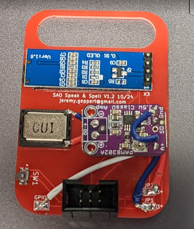
1Wire it up!
The board comes with the OLED and speaker already attached.
1. The purple audio/amp board needs to be stuck to the back of the board with the included foam double stick dot. Not the orientation to the speaker.
2. The switch gets installed on the pads labeled SW1. Bias the switch so the button sticks out further so you can reach it. It's small and hard to press if recessed too far.
3. Connect the wires as shown in the photo. The photo shows much larger wire than you will find in the kit. You can run the wires from the backside of the audio amp board if you want it cleaner. It's easier to just stick the amp board on and then add wires.
-Power wires feed off the solder jumper pads for the OLED display on the lower right side of the board. This gives you the option for OLED Displays that come with different polarities. It's a convenient place to pick up power.
-Short wires from the board to the speaker. Don't worry about polarity.
-The ground needs to also jumper to the A- on the input side (right side) of input.
-The GPIO2 pad on the lower left of the board needs to connect to the A+ on the audio amp input (right side).
4. 6 Pin SAO connector. Solder this from the front. Consider mounting this with the pins flush with the surface on the front of the board. This will give more clearance for all the shenanigans on the back of the board and whatever badge you put it on.
![]()
SAO Speak and Spell
First PCB board design and SAO in one project motivated by Supercon 2024
Discussions
Become a Hackaday.io Member
Create an account to leave a comment. Already have an account? Log In.