Nathaniel VerLee
-
On to the Next Rev, A code update
04/08/2015 at 00:07 • 0 commentsI have been digging through lots of TI literature on how to use their libraries to control my solar generators power conversion hardware. This is a fair amount of new code territory for me as the way the write these algorithms its all in optimized assembly to reduced the number of processor cycles needed for running these algorithms. I am going to be working towards a goal of simply regulating the output voltage of the converter, and then from there will move on to implementing a more advanced version of a "perturb and observe"MPPT algorithm.
In other news I have started reworking the board with fixes to many of the bugs I have found and changes to many of the components I am using. I will be doing a bit of cost reduction and component optimization along the way, and have gotten ride of a few things, mainly the 5V rail. I am hoping to get the next revision out in a month or two, but there is still plenty I can do with the hardware I have now.
-
More Coding Progress
02/11/2015 at 14:54 • 0 commentsI have been getting a good sense of how I am going to write the firmware for this project, with three basic timer loops that run high priority/frequency, medium priority and low priority tasks. Examples of higher priority tasks will be ADC sampling, power computation, MPPT and voltage regulation algorithms, and some examples of lower priority tasks would be updating the display and responding to button pushes, changing the state of the charging algorithm, and turning on and off loads. The next big tasks will be to write a voltage regulation algorithm and potentially integrate it into the MPPT algorithm, as well as getting a battery charge algorithm to begin testing with.
On the hardware front I have started to compile a long list of upgrades and changes to make to the next board revision, and I hope to get working on the next board once I prove out the current hardware.
-
I Blinked an LED today
12/31/2014 at 20:36 • 0 commentsWhich Personally, I consider a significant accomplishment. It has been awhile since I wrestled with configuring the compiler for a specific device and It took some doing to get my projects working with the new device. I am more of a hardware person, can you tell?
-
Communication Success!
12/30/2014 at 14:12 • 0 commentsAfter fixing some pullup/pull down and properly connecting the JTAG programming wires, I have successfull gotten code composer to talk to this new micro, so the next step be to port my code over to the new micro (Now the C2000 TMS320F28035, Previously the TMS320F28027 for the prototype). I will probably start with a blinking LED "hello world" and then start trying to get the micro to read from the sensors and switch the FETs.
-
Finally Testing the new Board
12/29/2014 at 17:26 • 0 commentsAfter assembling one of the three boards I had fabricated, I have finally gotten a chance to start testing. A new job and move process has put a lot of my side projects on hold and I am finally getting the chance to return to this project. The first step was to verify that the 1.8, 3.3, 5 and 12V rails were working properly. I made a silly mistake with the 12V boost converter: I entered the schematic as if it was a buck. It was an easy enough rework to do with a piece of kapton and some wires. I also made the easy mistake of getting the wrong IC package for the TPS54360 that I am using for the 5V buck converter. After I got all the rails up and working I moved on to connecting them to their respective loads and discovered a lovely dead short on the 3.3V rail (on the digital side). The 3.3V supply powers two rails - an analog and a digital one. Each is isolated from the other via a Pi filter, which is a kind of cap-ferrite-cap arrangement designed to prevent noise created by pulsating digital currents from the micro from propagating into the analog instrumentation circuits. It was the digital rail that appeared to be shorted, and after removing the micro this proved to be the case. After thoroughly inspecting this rail there are no visible mistakes in the layout files, and since most of these traces are in one of the midlayers I can only assume that they became shorted because I got too close to a manufacturing tolerance. In any case it was easy enough to rework, and the next steps will be to start getting code on the micro and get the buck stages up and running. From there I will be tweaking the voltage and current measurement circuits (they probably need a low pass with a steeper roll off) and trying to write a basic 3 stage battery charging algorithm.
-
About time for an update... Board is here!
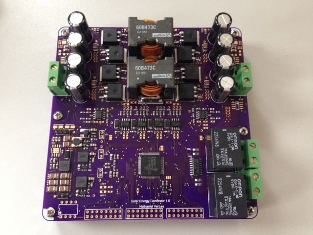
11/04/2014 at 18:23 • 0 commentsIt has been awhile, but the boards came about two weeks ago and I started assembling them. Here is the first sone below. You can already see in the middle left area there is a silly mistake... oops. Kinda forgot that was a boost, not a buck, when I was doing the schematic capture. I havent found any show stoppers though. As I am in the middle of moving I have not had much time to start testing and validations of the circuits. As soon as I get my lab equipment set back up im hoping to do just that.
![]()
-
Project Rendering Added
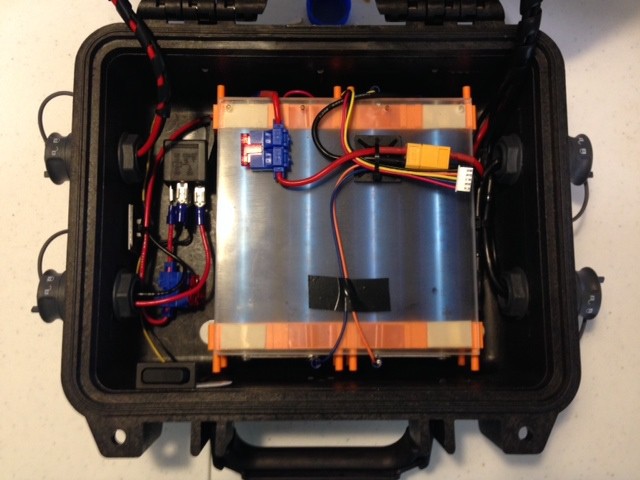
09/29/2014 at 03:02 • 0 commentsIts not quite an artists concept, but I think it does an ok job of illustrating the point. Here is a photo of the actual case that I have, and have been using with a 150WHr battery, albeit with a charge controller that I purchased. You can see the waterproof circular connectors on the case and wiring, load relay, and in-line fuses in this photo. I plan on changing the connectors out with Souriau UTS connectors - I don't really care for how the current Bulgin 6000 ones mate. My new PCB will eventually be assembled and eventual put into this case as a test platform.
![]()
-
Schematic and BOM Added
09/28/2014 at 23:41 • 0 commentsI have added a schematic and BOM here. While you can see some of the main components used in the component listing on Hackaday.io, the full BOM and schematic can be found at that link.
-
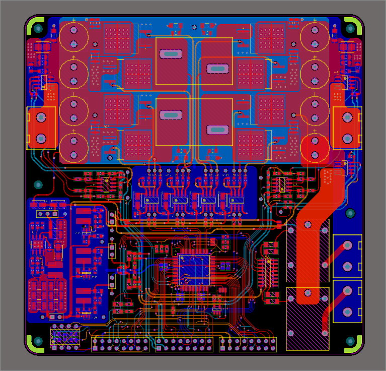
PCB is finally done!
09/27/2014 at 21:43 • 1 commentAdmittedly, I spent a bit too much time on this board - I wanted it to be perfect. I know there will need to be another revision before its ready to be called "done" but I wanted to give the first run my best effort. This has pushed me behind in terms of continuing to work on software, and before I do focus back on the software there will be a big push to finalize the materials needed on my BOM.
![]()
-
Update on PCB, and a side project...
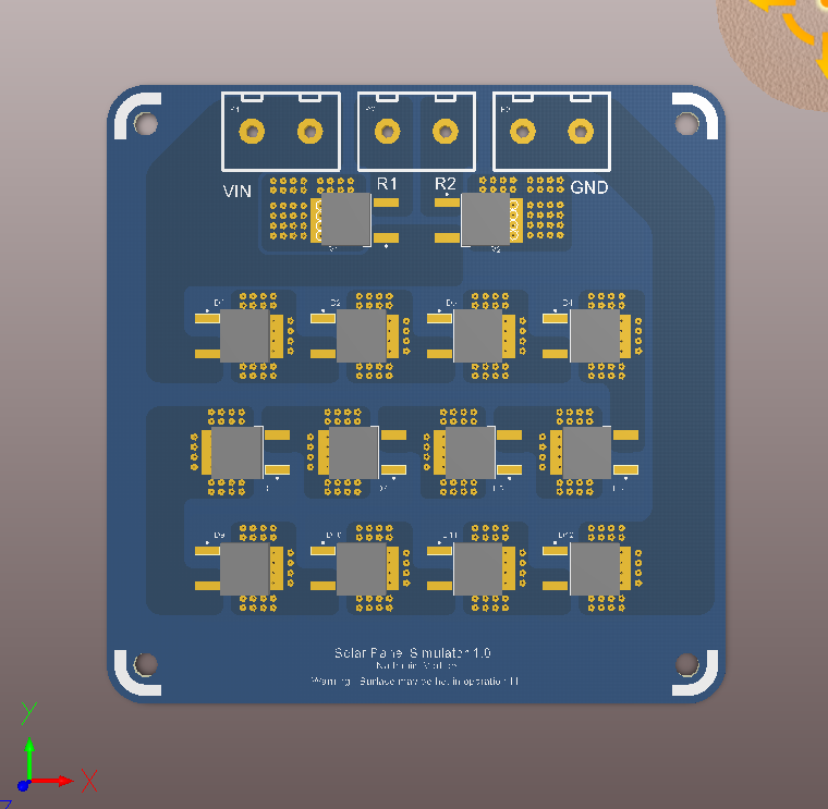
09/15/2014 at 12:16 • 0 commentsI have been hard at work routing the final PCB, and its coming out quite nicely. It doesn't look a whole lot different from the photo I previously posted because most of the work has been routing, and the placement was mostly finalized. The final design should go out tonight. In addition, I had a nice little distraction that has already been sent off to OSH park. This "Solar Panel Simulator" is a rather simple way to turn a power supply (which must be capable of doing CC limiting) into a panel simulator. The concept is rather simple: you hook it up in parallel with the supply, set in CC mode, and the thing you want to power (my project) and the power supply now appears to the load to have the V-I characteristic of a solar panel. The diodes basically act as a shunt and sink all the current when the load is not drawing anything. This will be very useful for all those cloudy days and late nights that I have wanted to test my system in accurately simulated conditions.
![]()
Solar Energy Generator
A solar energy system up to 500W in power for use with lithium batteries.