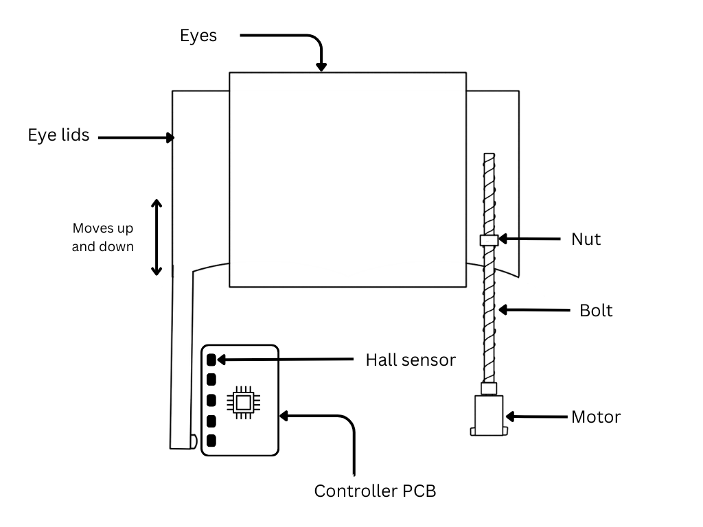
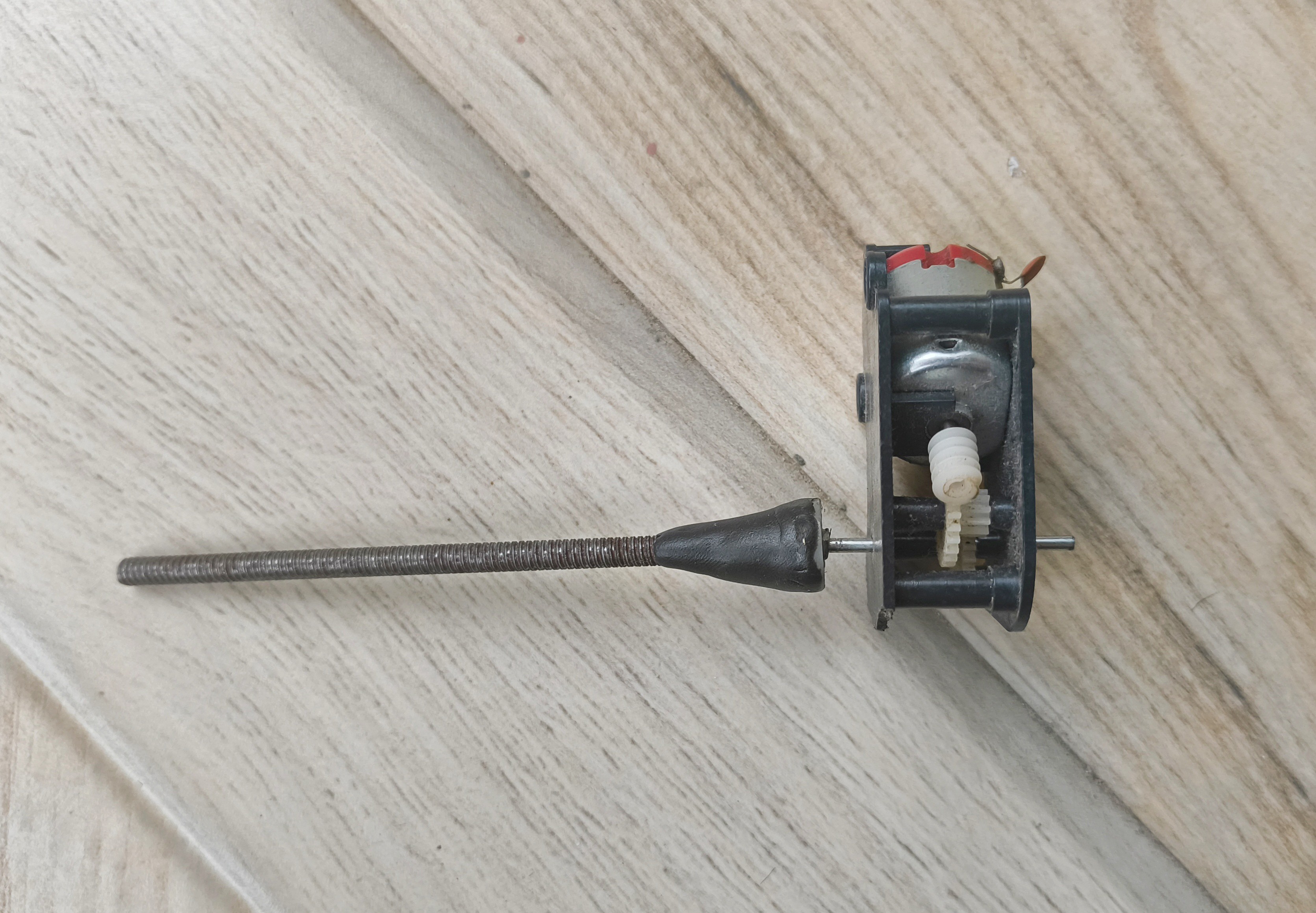
The main components of this project are the MQ135 air quality sensor and a Xiao esp32 microcontroller. The setup also contains five hall effect sensors, each one mapped to a certain CO2 ppm level. A motor is connected to the microcontroller through an L293D motor driver IC. This motor is a DIY linear motor that moves the eyelids up or down depending on the direction of rotation. The eyelids contain a magnet at the long end that can be detected by the hall sensors.
The microcontroller reads the MQ135 sensor’s analog output and converts them to the CO2 ppm levels with some math. This is done for a specific duration (5 minutes in my code) and the ppm values are averaged for that duration. Then, the microcontroller turns the linear motor on until the magnet is in front of the hall sensor that corresponds to the same ppm (within a tolerance range). This way the eyelids move to match the ppm level.
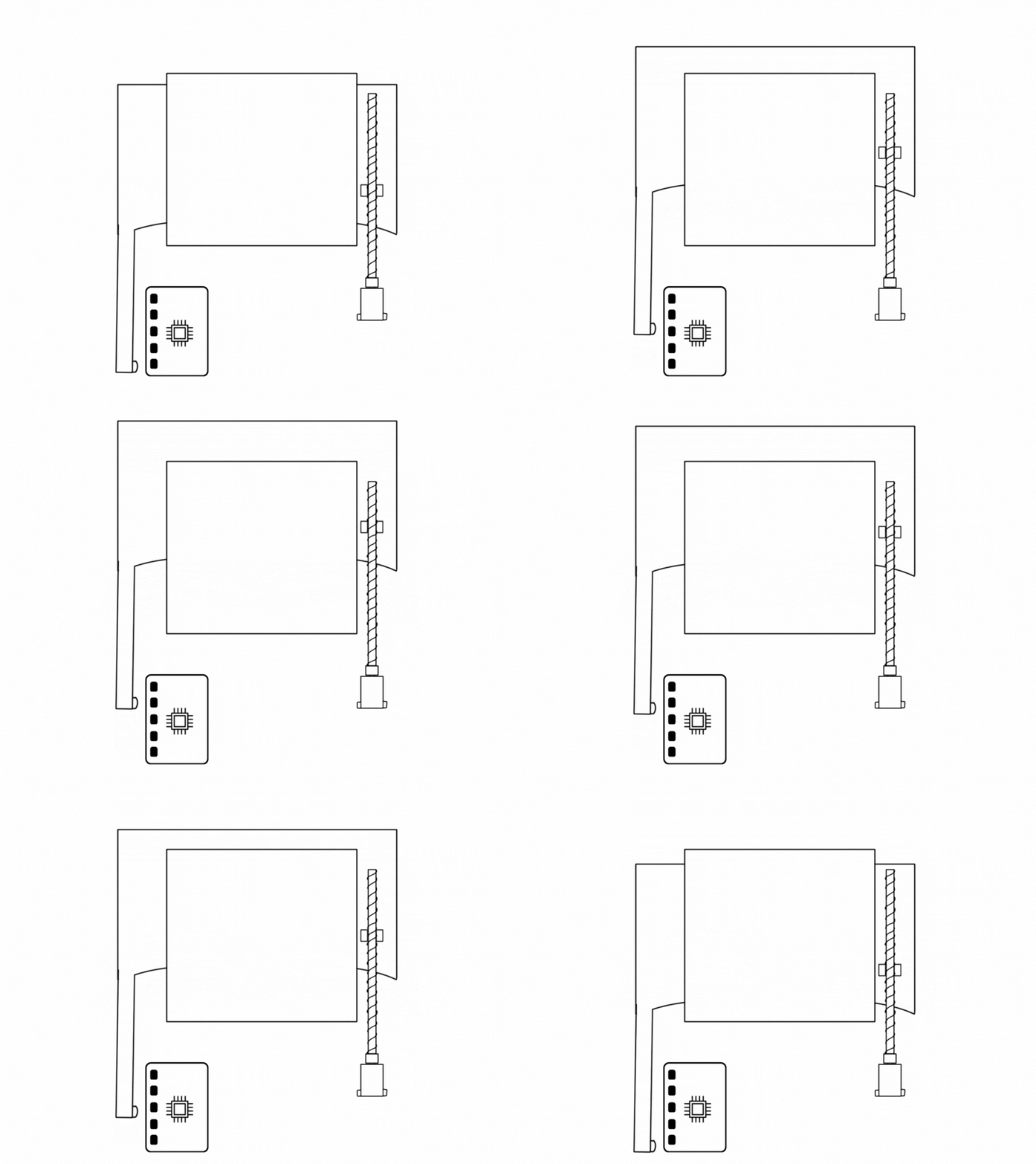
This can be done in several different ways. My earlier plan was to have a linear variable resistor (also called a slide potentiometer) in place of the hall sensors and magnet. The slider would be connected to the eyelids. When the motor would move the eyelids up or down, the slider would move along with it and change the resistance. The microcontroller could map the ppm level to the right resistance to achieve the same effect of indicating CO2 levels with the eyelids. However, I later discovered that slide pots have a working life of about 15,000 cycles after which they don’t function well. Even if the eyelids move 50 times a day, the pot will reach end of life in less than a year. So that would not work.
Another way would be to use an ultrasonic distance sensor to detect the distance of the eyelids relative to itself. This is a feasible way. I came up with this only after I ordered the PCB with the hall sensors, so I stuck with that.

 Paul Fjare
 SimpleTronic
 kodera2t