In the work period of November 9th to November 23rd, we had the goals to finalize the CAD design of the steering wheel with paddle shifters, selecting the pneumatic components, conducting thermal analysis for insulation on the pneumatics, designing the electrical system, and developing the Arduino program. The steering wheel has gone through design revisions as feedback was obtained from Cougar Racing drivers and FEA models. A Design Matrix was created to compare 4 different versions of the steering wheel (figure 1); the numbers were determined from the drivers themselves and from our input.
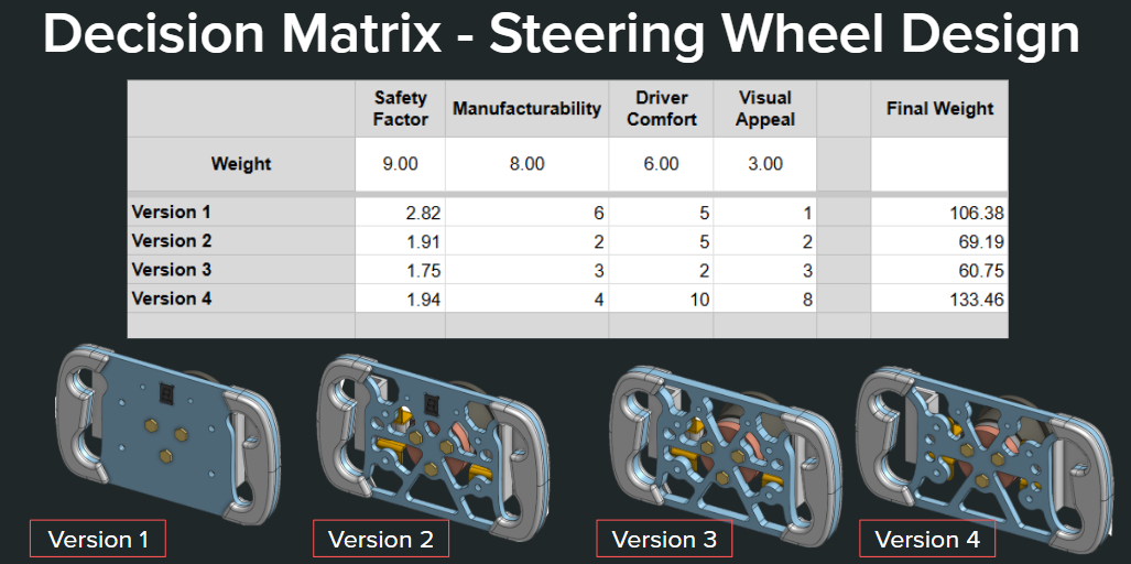
Versions 1-3 were different wheel designs, though had the same width and handle geometry. After a meeting with the drivers and the Machine Man Interface leads they recommend a wider steering wheel and bigger handles for comfort. This has led to the creation of the 4th version after optimization to achieve a higher safety factor while reducing the overall steering wheel thickness down to 0.25” as version 3 was 0.375” thick. Figure xx shows the difference between version 3 & 4, respectively. 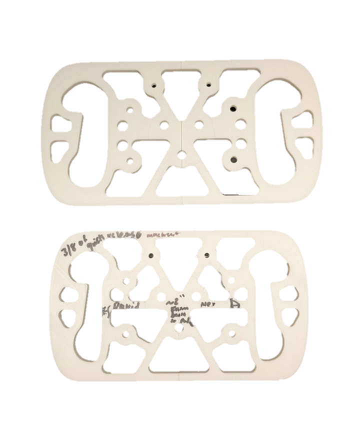
Version 4 has markings on the steering wheel, they represent the placement of the drivers hands when they’re at their most natural position. This was considered in the CAD as it changes the geometry of the paddles.
The progress for pneumatic components complete was the creation of the pneumatic system components with options for the cylinder, solenoid, pressure regulator, and tubing. In addition, specifications for these components are needed have been selected using a tabulation of scores with comparisons. This portion has been completed through selection of criteria that are important and will ensure an efficient result.
The pneumatic components progress has tasks that have been completed and are still in progress.
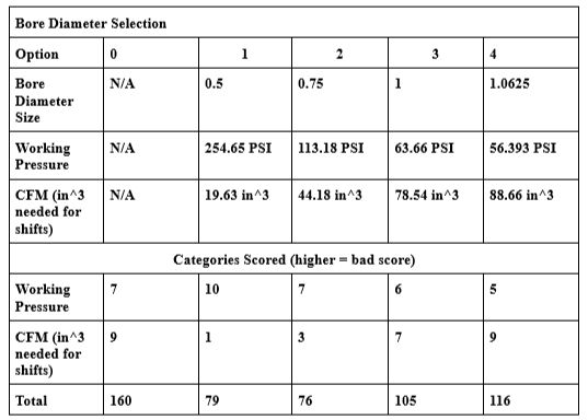 Figure 3: Tabulation for Bore Diameter Selection
Based on the tabulation, the ideal bore diameter will be 0.75” as it makes effective use of its working pressure to output 50 lbf with a relatively low volume of compressed air needed for 100 shifts. With the bore diameter determined, we can put together a system of components focusing on the 0.75” bore diameter, however in case of limited options, the system will have the next best option as well, in this case, due to limited availability of cylinders, 1.0625” bore diameter has been selected. To select the best pneumatic cylinder for a system, we have the choice of one multi-stroke cylinder or two single acting cylinders to perform the upshift and downshifts. The multi-stroke cylinder will take up less volume and will be a simpler mount, so a larger set of options was made for the multi-stroke cylinder. The selection of the pneumatic cylinder is based on the following tabulation:
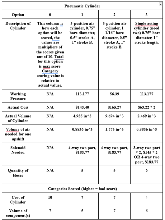
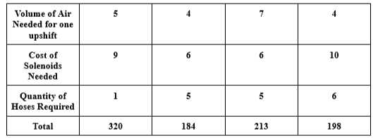 Figure 4: Tabulation for Pneumatic Cylinder Selection
From the options created, the best choice is the 0.75” bore diameter multi-stroke cylinder based on cost, volume of the component and air, and hoses required. The cost itself is to be within budget, and the hoses quantity will cause problems in cable management due to lack of space available in the engine bay. Finally, the last tabulation for the pneumatics is for the air tank. The hoses, pressure regulator, and solenoid were selected based on compatibility, required specifications, and safety. For example, one compatibility feature is based on threading for the hoses to fit onto the cylinder. The required specifications are based on components, for instance, the air tank’s default pressure regulator outputs at 500 PSI, so we need another regulator to decrease it to 300 PSI, the easiest way to do this is using the air tank manufacturer’s adjustable regulator that will output at 300 PSI. From there, the pressure regulator needed is one that is rated to intake 300 PSI. As for safety, desired safety features for components are desired as heat will cause the pressure to increase, so we will have insulation to prevent this and in addition, safety features such as a relieving valve on the pressure regulator will be included. Therefore, the air tank will need a tabulation score to be selected which can be found below:
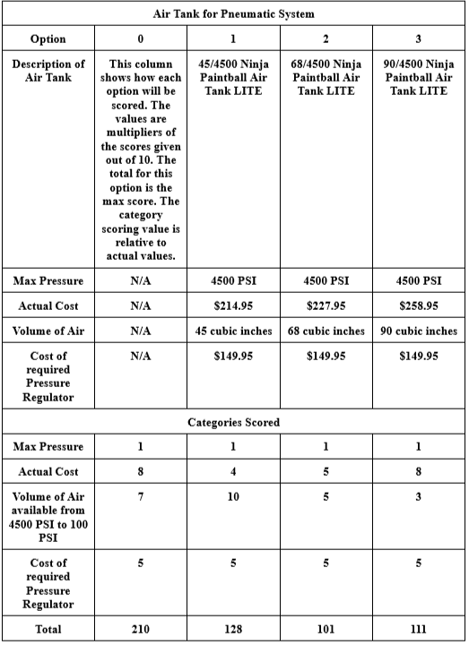 Figure 5: Tabulation for Air Tank Selection
Based on the score, the best choice will be the 68/4500 air tank as it makes the most effective use of volume with the maximum pressure. The 90/4500 air tank is still a valid option though as it can be used at a lower pressure for safety and contains sufficient volume for compressed air required for 30 minutes of use.
The tasks in progress for the pneumatic component is the thermal studies modeling, however, currently some heat transfer calculations were made to determine the conditions. Using a heat conduction model of the engine with the conduction coefficient of mild steel, we can estimate the heat transfer to air which is around 83 ℃ or around 392 ℉. Based on this value, insulation can be chosen that is rated to withstand more than the heat transferred to the air. Although the thermal study model can help, knowing the temperature the air will be at is more useful to estimate the specifications needed for insulation. Therefore, silicone rubber filled with fiberglass will be used as insulation material for pneumatic components which is rated at a working temperature of 500 ℉.
For the electrical system, we were able to develop an initial design with the use of Tinkercad, allowing us to get a preview of what electrical components the project will be requiring. In Figure 6, the 12 V battery provided by the car will power the solenoids. Since the Arduino can only provide 40 mA at 5 V to its pins, transistors (TIP120) will allow for the Arduino to handle the higher electrical loads from the 12 V battery. Two switches integrated into the steering wheel will dictate the downshift and upshift functions.
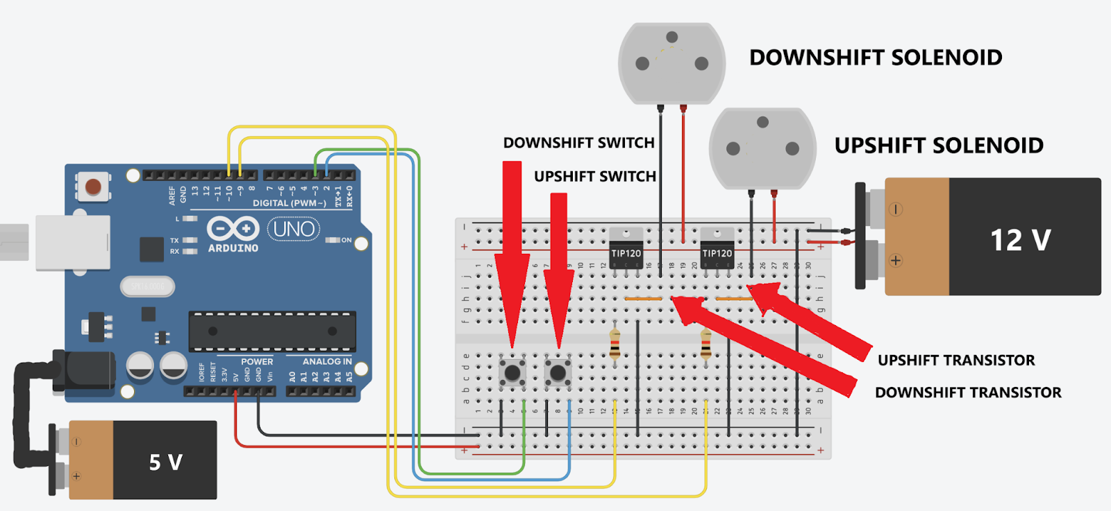
Figure 6: Arduino Sample Circuit
Additionally, we developed an initial iteration of the Arduino code. During the writing process, failsafes came to mind that will prevent damage to components from the pneumatic system or inside the engine if the driver were to ever accidentally initiate a shift while the engine’s revolutions per minute (RPM) were not at an adequate range to do so.
Our final design focuses on a comprehensive paddle-shifting system that addresses key challenges in performance, integration, and driver ergonomics. The design is divided into three sub-systems: pneumatics, electronics, and the steering wheel.
The pneumatics sub-system includes a 3-position piston to engage the engine clutch lever, a 68 in³ air tank to sustain system operation for at least 30 minutes, and solenoids controlled by the electrical system to actuate the piston. This ensures reliable and precise shifting over extended periods.
The electronics sub-system is powered by an Arduino that collects data from the tachometer and the driver's input via buttons. Custom code processes this information to validate shifts and prevent user errors that could damage the engine, ensuring both functionality and safety.
Lastly, the steering wheel sub-system was entirely redesigned to integrate paddle shifters effectively. Retrofitting the existing wheel proved impractical due to limited space, so we fabricated a new wheel that accommodates the necessary electronics while improving driver ergonomics. This approach prioritizes comfort and usability, shifting the focus from merely "steering the car" to truly "accommodating the driver."
Overall, this design resolves the identified issues by delivering a seamless, ergonomic, and reliable paddle-shifting system.
The key analytical results at this stage highlight the successes and strengths of our design, particularly in the steering wheel and pneumatic systems.
Steering Wheel Analysis
The analytical results for the steering wheel were obtained through FEA (Finite Element Analysis), which provided the safety factor of the new design. This ensures the wheel meets structural integrity requirements while accommodating the integration of paddle shifters and improving driver ergonomics.
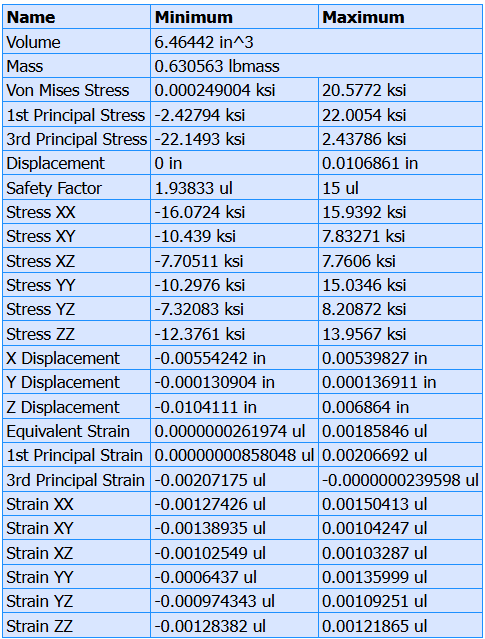 Figure 7: FEA Results
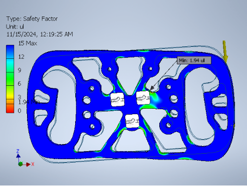
Figure 8: FEA Simulation Model
Pneumatics Analysis
The pneumatic system's design is supported by detailed parameter analysis, including pressure, compressed air volume, flow rate, temperature, geometry, and heat transfer.
-
Air Tank Selection: A 68 cubic inch air tank, rated for a maximum pressure of 4500 PSI, was selected. It includes a built-in pressure regulator outputting at 500 PSI. Due to the availability of low-pressure regulators with limits between 300-400 PSI, an additional adjustable pressure regulator will be purchased from Ninja (the air tank manufacturer) to step down pressure to 300 PSI. This is further regulated to a range of 50-125 PSI, ensuring modularity for various operations.
-
Component Specifications: The solenoids and hoses were selected to match the system's 50-125 PSI range. Calculations confirmed compatibility and operational safety.
-
Pressure and Force Calculations: Using force/area (F/A) calculations based on the piston area, the working pressure required to generate 50 lbf was determined. Geometry calculations, using the similarity of triangles and the Pythagorean theorem, determined the piston’s minimum stroke length to be 0.6478 inches.
-
Compressed Air Volume and Capacity: Using a single-stroke cylinder model, the compressed air volume needed for optimal operation was estimated. At working pressure, the volume is approximately 795.22 cubic inches, or 20.322 cubic inches at 4500 PSI. For 30 minutes of operation at 60 shifts per minute, the 68 cubic inch air tank provides sufficient capacity to supply the pneumatic components.
-
Heat Transfer and Insulation: Engine heat transfer is estimated to raise the air temperature to 84.73℃. Insulation will be necessary to prevent overheating, which could lead to increased working pressure and potential system instability.
-
Flow Rate and Activation Time: Using Bernoulli’s equation and pressure differences from the regulators to the hose, the estimated fill time for one foot of hose at 115 PSI is approximately 0.001 seconds. This supports achieving the desired 0.4-second activation time from paddle input to engine gear shift actuation.
These results demonstrate the reliability, efficiency, and safety of our design. They validate that the system can handle operational demands, meets performance criteria, and provides flexibility for future improvements.
Looking ahead to Capstone II, our team has outlined several key preparations to ensure we are ready to execute our design by the start of the Spring 2025 semester.
Steering Wheel Preparations
We will coordinate with Sulzer to finalize access to their large CNC machine, identifying an appropriate time frame that avoids interfering with their business operations. Using Inventor’s CAM (Computer-Aided Manufacturing) add-on, we will generate the necessary G-code for manufacturing the aluminum steering wheel. To minimize material waste, we plan to create test pieces from scrap metal or wood before ordering the 6061 aluminum stock. This approach ensures precision and reduces potential delays.
Pneumatics Preparations
For the pneumatic system, we have preselected components, but availability will need to be confirmed with suppliers before the Spring semester begins. Additionally, we will finalize the mounting points for key components, including the air tank, pneumatic cylinder, solenoid, and pressure regulator.
Collaboration and Integration
Close collaboration with the UH FSAE team will be crucial to ensure all subteam components are well-organized and that the pneumatic components are efficiently integrated into the overall system. This teamwork will streamline the mounting process and address potential conflicts early.
By completing these preparations, our team will enter Capstone II equipped to execute the design smoothly and effectively.
Discussions
Become a Hackaday.io Member
Create an account to leave a comment. Already have an account? Log In.