The team’s project progress from January 13th to February 1st has been the rework of the pneumatic components due to stock issues and changes in plans, paddle shifter improvement, and purchases of materials.
The pneumatic components were reworked to increase the volume of air and stock issues. Originally, the team wanted to use a ninja 68 cubic inch tank rated for 4500 PSI with a custom regulator outputting 120 PSI, however, this regulator went out of stock as it is very common for FSAE teams to use this. A local shop with limited supplies also fabricates the component, so it sold out quickly. To upgrade the volume, the 90 cubic inch tank rated for 4500 PSI was selected but it went out of stock as well (this can be seen below).

Figure 1: Regulator and Tank Sold Out
As an alternative to the 90 cubic inch tank, the team opted for a larger tank that is still available, therefore the 80 cubic inch tank from HK Army was purchased and was delivered on 1/31/2025. To regulate this pressure, the team will utilize the adjustable HK Army regulator rated at 250 to 300 PSI which was delivered on 1/31/2025. Because our working pressure is 120 PSI, another regulator is needed which will be purchased from McMaster Carr, it will be ordered alongside the 4/2 solenoid and hoses needed. The solenoid, hoses, and fittings needed for the pneumatic system are currently pending revision to guarantee proper fit in the system. This revision is necessary to minimize downtime usage later on by making sure parts are compatible and are the most economical.
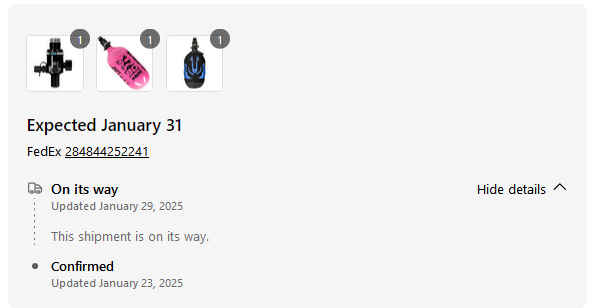
Figure 2: Tank and Regulator Delivery (Tank guard given for free)
Additionally, the pneumatic cylinder has been purchased and delivered to confirm the solenoid needed as the specifications weren’t sufficiently detailed. Based on current findings, the cylinder has three inlets, one inlet actuates 0.5 inches of the cylinder extension, the second inlet actuates 1 inch of the cylinder extension, and the third inlet retracts the cylinder all the way. Considering this, we will need two simultaneous air flow directions at a given time. In our capstone project, the 0.5-inch stroke A will be used as the neutral starting position. Therefore to upshift, the pneumatic cylinder will need to actuate the 1-inch stroke B extension to engage the engine gear shifter to go up a gear, as soon as the gear is shifted, the cylinder will then instantly retract to the starting position. The programming will be essential for the cylinder to return to the neutral starting position here because the retraction inlet does not have a limit of retraction distance. This means that if we want to retract the cylinder following the 1-inch stroke B extension, upon airflow to the retraction inlet, the cylinder will retract completely to an extension of 0 inches which is an issue. The retraction inlet has no limit of retraction, so if we want to ensure the neutral starting position is at 0.5 inches, we will need the cylinder to retract back to a 0.5-inch extension or slightly further, then simultaneously allow airflow to the 0.5-inch extension. Essentially, the extension and retraction will need to be actuated in such a way that the cylinder retracts back to 0.5 inches of extension following the engine gear shifting. These conclusions were drawn based on the physical testing of the cylinder, a screenshot of this is shown below.
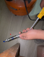
Figure 3: Pneumatic Cylinder Testing
Based on the testing, the 4 way two-port solenoid is confirmed to be the necessary component needed to purchase (an example of this solenoid is provided below).
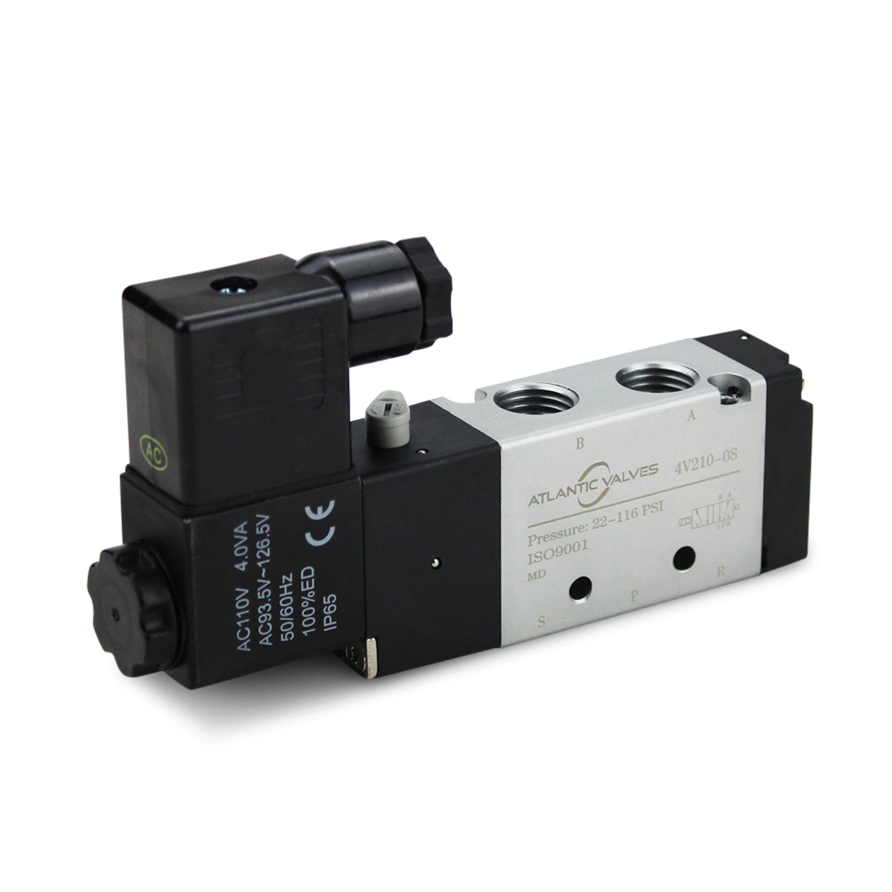
Figure 4: Sample 4/2 Solenoid
With this solenoid in mind, the programming of the Arduino can be updated to address the flow ports correctly for initial testing in validation.
The HPA carbon fiber tank will require a shield to protect the driver and audience’s safety. This shield and the steering wheel will be manufactured with aluminum. The plan in capstone 1 was to use aluminum 6061, however, based on quote estimates and material availability, we may use aluminum 5052 instead. An additional change for the shield will be the update to the final design. Originally the shield was planned out to be a hollow rectangular prism to fully enclose the tank, however, that design uses an unnecessary amount of material increasing weight and material cost. The updated shield the team plans on making is shown below.
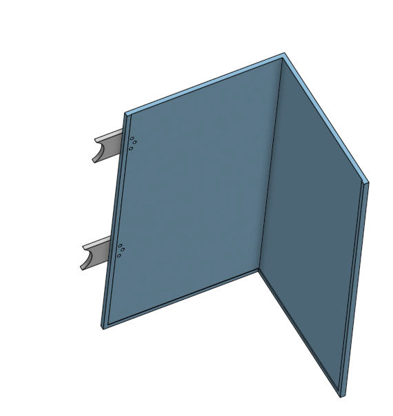
Figure 5: Updated Air Tank Shield
Using the time between February 1st to February 15th, the pneumatic component purchase selection will be finalized and purchased, ideally delivered before the 12th to begin assembly and validation. The remaining needed components for the pneumatics are the solenoid, hose, fittings, second pressure regulator, insulation, and aluminum material. The major milestones desired to achieve with the components are initial testing and assembly, solenoid programming, and validation. The initial testing for the pneumatic components will mainly focus on the verification of component compatibility. For instance, the HK Army tank has a stock regulator, so installing the new regulator is needed as well as testing to ensure part functionality. In addition, because the pneumatics will need an open-air flow from the tank to the hose, an on/off valve has been purchased and delivered (the component is shown below). Using this component, once the tank and regulator arrive, initial testing of this is available to verify functionality.
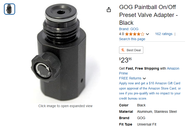
Figure 6: On/Off Adapter for Tank
The validation to complete for the pneumatics is the force output of the cylinder, temperature changes from running engine measured directly from engine and insulation, failure stress of mounting tabs, and air leakage from the pressurized pneumatic system. As part of this work period, validation planning is necessary to stay on schedule.
Discussions
Become a Hackaday.io Member
Create an account to leave a comment. Already have an account? Log In.