- For the work period of January 13 - February 1, what work toward your team's project has been completed? Please provide a description of tasks that are completed, as well as tasks currently in progress.
The team’s project progress from January 13th to February 1st has been the rework of the pneumatic components due to stock issues and changes in plans, paddle shifter iterations, and purchases of materials.
The pneumatic components were reworked to increase the volume of air and stock issues. Originally, the team wanted to use a ninja 68 cubic inch tank rated for 4500 PSI with a custom regulator outputting 120 PSI, however, this regulator went out of stock as it is very common for FSAE teams to use this. The component is also fabricated by a local shop with limited supplies, so it sold out quickly. To upgrade the volume, the 90 cubic inch tank rated for 4500 PSI was selected but it went out of stock as well (this can be seen below).
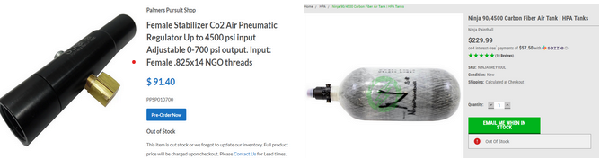
Figure 1: Regulator and Tank Sold Out
As an alternative to the 90 cubic inch tank, the team opted for a larger tank that is still available, therefore the 80 cubic inch tank from HK Army was purchased and was delivered on 1/31/2025. To regulate this pressure, the team will utilize the adjustable HK Army regulator rated at 250 to 300 PSI which was delivered on 1/31/2025. Because our working pressure is 120 PSI, another regulator is needed which will be purchased from McMaster Carr, it will be ordered alongside the 4/2 solenoid and hoses needed. The solenoid, hoses, and fittings needed for the pneumatic system are currently pending revision to guarantee proper fit in the system. This revision is necessary to minimize downtime usage later on by making sure parts are compatible and are the most economical.
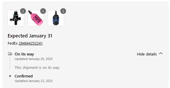
Figure 2: Tank and Regulator Delivery (Tank guard given for free)
Additionally, the pneumatic cylinder has been purchased and delivered to confirm the solenoid needed as the specifications weren’t sufficiently detailed. Based on current findings, the cylinder has three inlets, one inlet actuates 0.5 inches of the cylinder extension, the second inlet actuates 1 inch of the cylinder extension, and the third inlet retracts the cylinder all the way. Considering this, we will need two simultaneous air flow directions at a given time. In our capstone project, the 0.5-inch stroke A will be used as the neutral starting position. Therefore to upshift, the pneumatic cylinder will need to actuate the 1-inch stroke B extension to engage the engine gear shifter to go up a gear, as soon as the gear is shifted, the cylinder will then instantly retract to the starting position. The programming will be essential for the cylinder to return to the neutral starting position here because the retraction inlet does not have a limit of retraction distance. This means that if we want to retract the cylinder following the 1-inch stroke B extension, upon airflow to the retraction inlet, the cylinder will retract completely to an extension of 0 inches which is an issue. The retraction inlet has no limit of retraction, so if we want to ensure the neutral starting position is at 0.5 inches, we will need the cylinder to retract back to a 0.5-inch extension or slightly further, then simultaneously allow airflow to the 0.5-inch extension. Essentially, the extension and retraction will need to be actuated in such a way that the cylinder retracts back to 0.5 inches of extension following the engine gear shifting. These conclusions were drawn based on the physical testing of the cylinder, a screenshot of this is shown below.
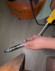
Figure 3: Pneumatic Cylinder Testing
Based on the testing, the 4 way two port solenoid is confirmed to be the necessary component needed to purchase (an example of this solenoid is provided below).
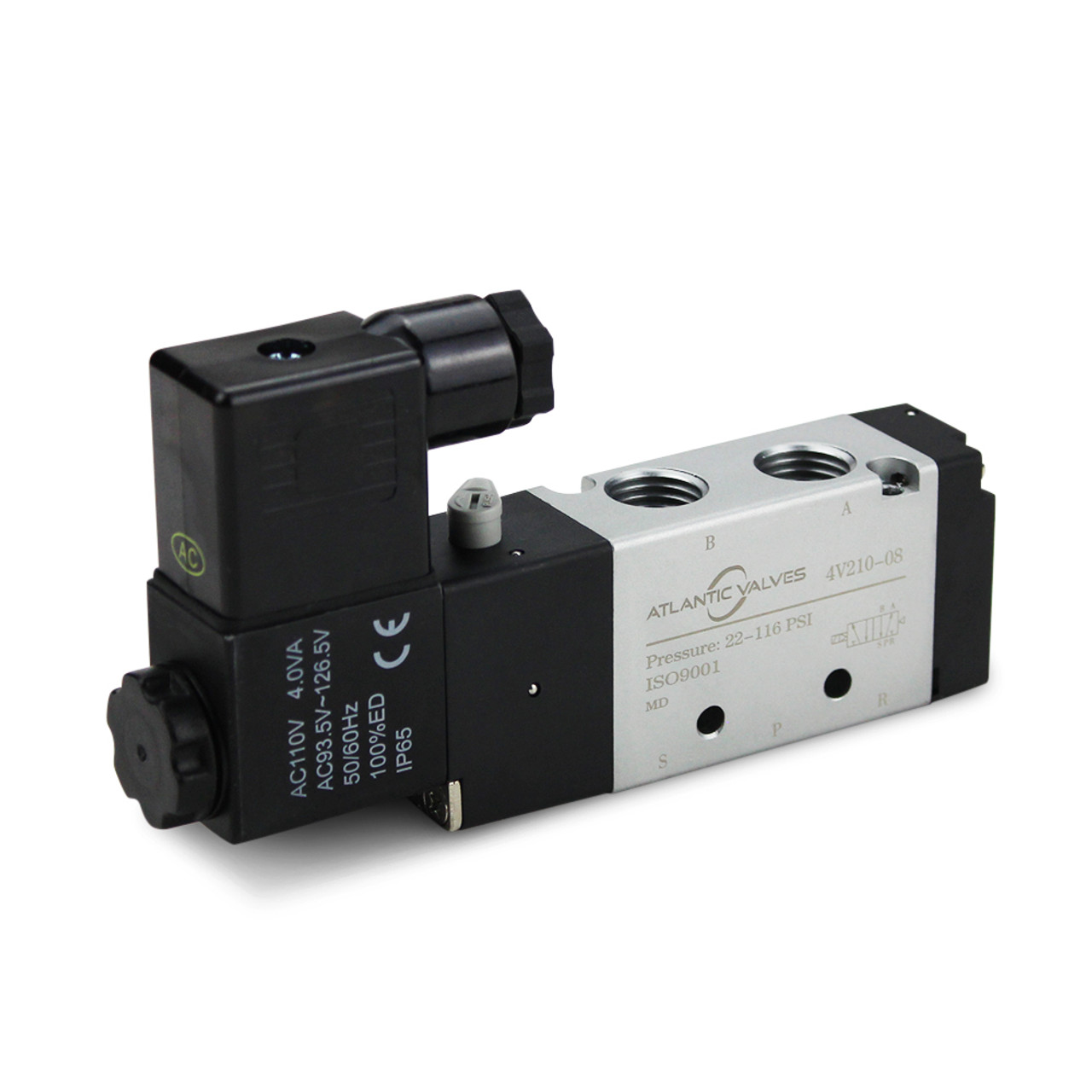
Figure 4: Sample 4/2 Solenoid
With this solenoid in mind, the programming of the arduino can be updated to address the flow ports correctly for initial testing in validation.
The HPA carbon fiber tank will require a shield to protect the driver and audience’s safety. This shield and the steering wheel will be manufactured with aluminum. The plan in capstone 1 was to use aluminum 6061, however, based on quote estimates and material availability, we may use aluminum 5052 instead. An additional change for the shield will be the update to the final design. Originally the shield was planned out to be a hollow rectangular prism to fully enclose the tank, however, that design uses an unnecessary amount of material increasing weight and material cost. The updated shield the team plans on making is shown below.
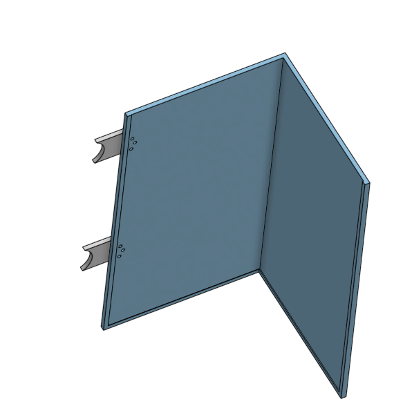
Figure 5: Updated Air Tank Shield
After driver input of the paddle shifter assembly, it has gone through another iteration and a rework of the overall mechanism. The previous assembly had an extremely tight engagement window as there was not a lot of resistance to activate the button. With the new iteration the button was switched out with a microswitch. It has more resistance so it is not prone to accidental activation and from driver’s feedback it is more tactile.
Moreover, the first physical prototype of the electronics was assembled after having been designed in Tinkercad, as shown in Figure 6. Missing components such as the solenoid and car battery have been considered in the design as well as the code and will be integrated once available.
To align with the shifting sequence of the current FSAE car (1-N-2-3-4-5-6), the code will need to begin in neutral otherwise the engine will stall upon startup. After that, the code will follow any input given by the driver if it’s downshifting into 1st or upshifting into 2nd and so on. Due to the engine that is used only having an “in-neutral” indicator and not a gear indicator, the code will need to splice into it to correlate when the car is in neutral to begin counting the shifts either up or down. This way of counting will serve as our gear indicator.

Figure 6: Starting in neutral gear
As previously mentioned, limit switches will be used for the downshifting/upshifting actions and a button switch for the neutral command. The neutral button will be located somewhere in the center of the steering wheel’s side facing the driver as shown in Figure 7 and Figure 8. The code has been made in that it will only allow the driver to press the neutral button if it reads that it is 1st gear. Pressing the neutral button in any other gear will be followed with an error command.
Additionally, the code will prevent the gear indicator from going below 1 or above 6, these being the lowest and highest gears in the car respectively. This is to prevent the pneumatic piston from being actuated accidentally and damage the engine gear shifter.

Figure 7: Left button for downshifting
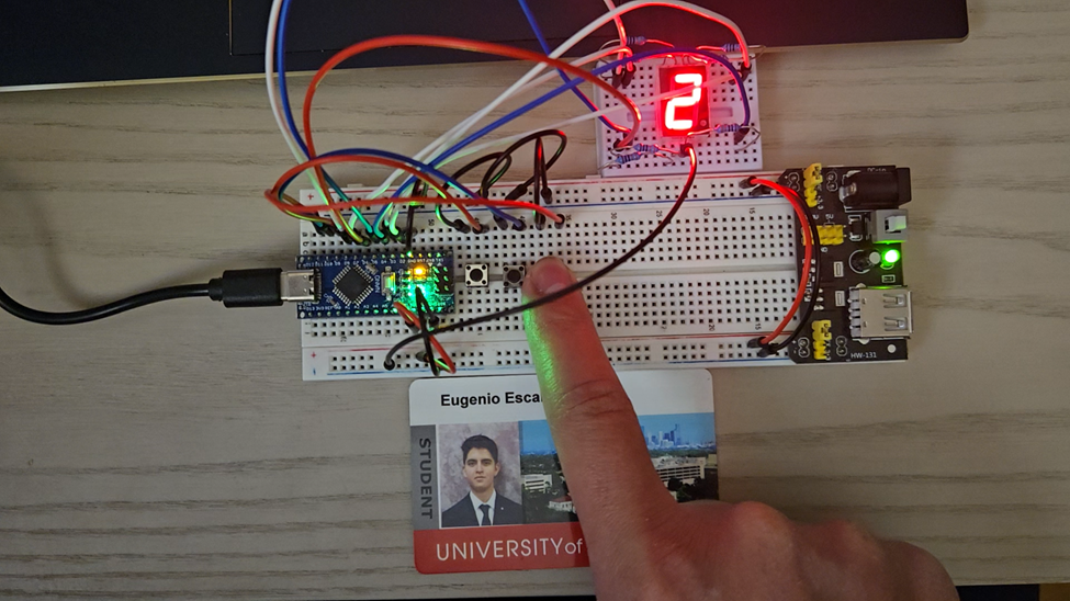
Figure 8: Right button for upshifting
2. For the work period of February 1 - February 15 what is your team's plan for near term work? What major milestones does the team hope to achieve in your work?
Using the time between February 1st to February 15th, the pneumatic component purchase selection will be finalized and purchased, ideally delivered before the 12th to begin assembly and validation. The remaining needed components for the pneumatics are the solenoid, hose, fittings, second pressure regulator, insulation, and aluminum material. The major milestones desired to achieve with the components are initial testing and assembly, solenoid programming, and validation. The initial testing for the pneumatic components will mainly focus on the verification of component compatibility. For instance, the HK Army tank has a stock regulator, so installing the new regulator is needed as well as testing to ensure part functionality. In addition, because the pneumatics will need an open-air flow from the tank to the hose, an on/off valve has been purchased and delivered (the component is shown below). Using this component, once the tank and regulator arrive, initial testing of this is available to verify functionality.

Figure 9: On/Off Adapter for Tank
The validation to complete for the pneumatics is the force output of the cylinder, temperature changes from running engine measured directly from engine and insulation, failure stress of mounting tabs, and air leakage from the pressurized pneumatic system. As part of this work period, validation planning is necessary to stay on schedule.
The steering wheel material will be purchased on Monday February 3rd. A quote was obtained for 2 plates of 5052 3/16”, 11” x 6”. The change of material did cause a change in the calculated safety factor, but we will still obtain our goal of the steering wheel being over 1.33.

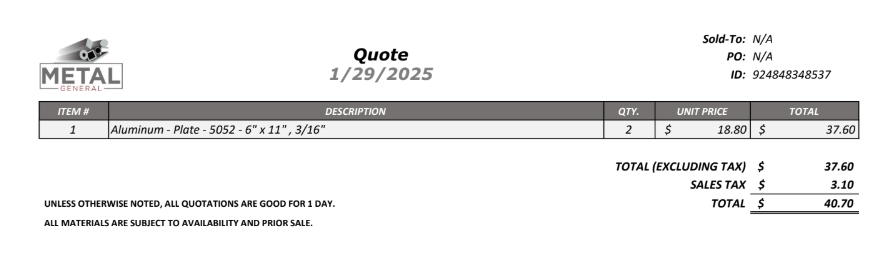
Figure 10: FEA Model of Steering Wheel and 5052 Aluminum Quote
The electronics assembly will be mounted with 3D printed steering wheel to confirm fitment as well as begin running the wire spool for exact wire length routed from the Arduino being placed near the cluster panel to the solenoid near the driver’s back.
3. What obstacles does the team foresee in your project work over the next two weeks? What solutions does the team have in mind and what back-up plans does the team have?
The obstacles foreseen in the next two weeks is the FSAE organization delays as the current car is being presented at different events so validation may be delayed. To use time efficiently, other validations that don’t require the car will be completed, for instance, the load cell validation of the pneumatic cylinder. Additionally obstacles foreseen is shipping times which could waste time further if parts aren’t ordered soon. This obstacle can only be amended by the team working in a timely manner on the capstone project.
4. Provide at least 3 figures to show the concrete progress and current status of the team's work. Please refrain from presenting your team's Gantt charts and from providing only photos of acquired materials with no further work.
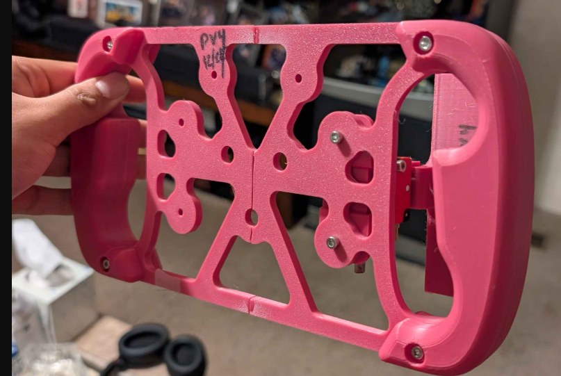
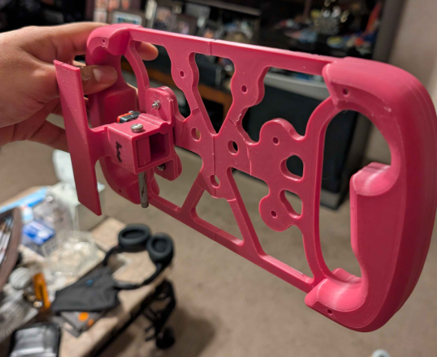
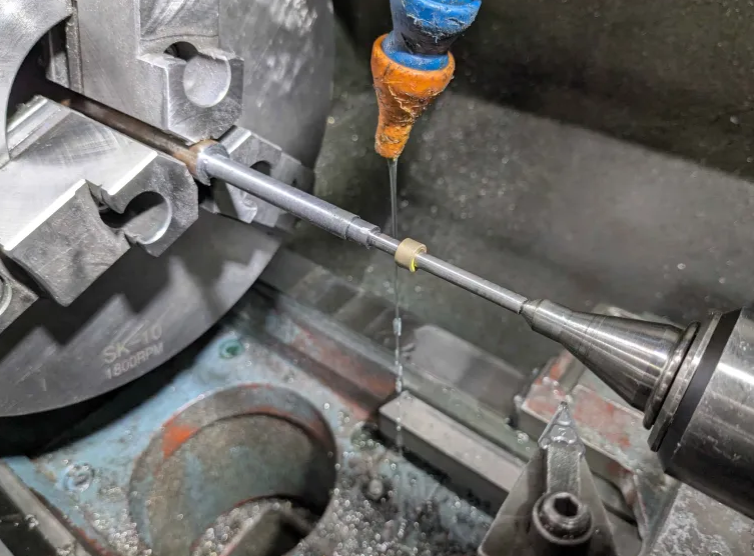
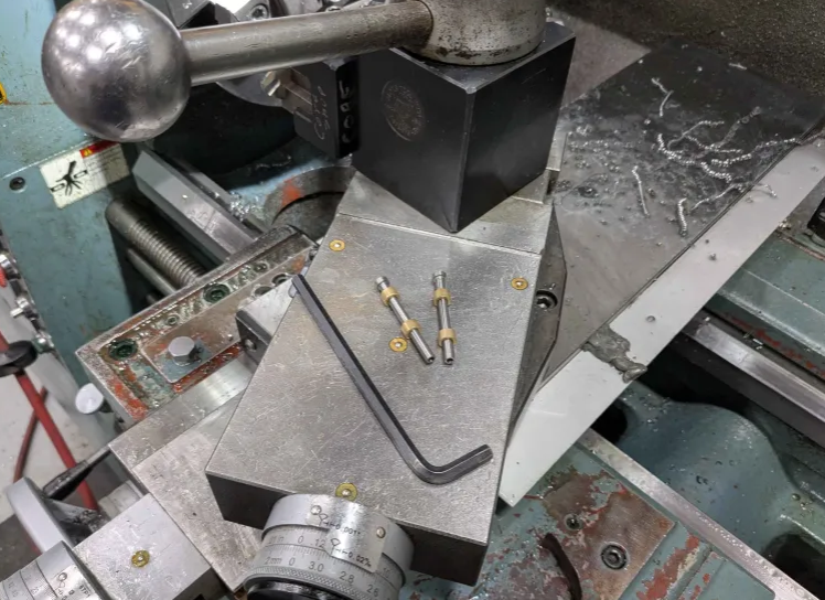
Figure 11: Fabrication of Pins for Paddle Shifter (photo collage)
Due to the rework done for the paddle shifter a set of pins and bushings was needed. Through McMaster-Carr each pin was $11 and a set of bushings was around $2, to further limit the usage of our budget the pins were fabricated at Sulzer from stock material found at the FSAE shop. As the components are not critical the composition of the metal is not known, but with the new design the paddles have no play and have a firm tactile click when engaged.
As previously mentioned the material 5052 plates of aluminum are being ordered, the steering wheel design is finalized and all that is left is the fabrication of the steering wheel. In figure 11 a 3D printed prototype was made to test out the fitment of the assembly and to check for interference.
Discussions
Become a Hackaday.io Member
Create an account to leave a comment. Already have an account? Log In.