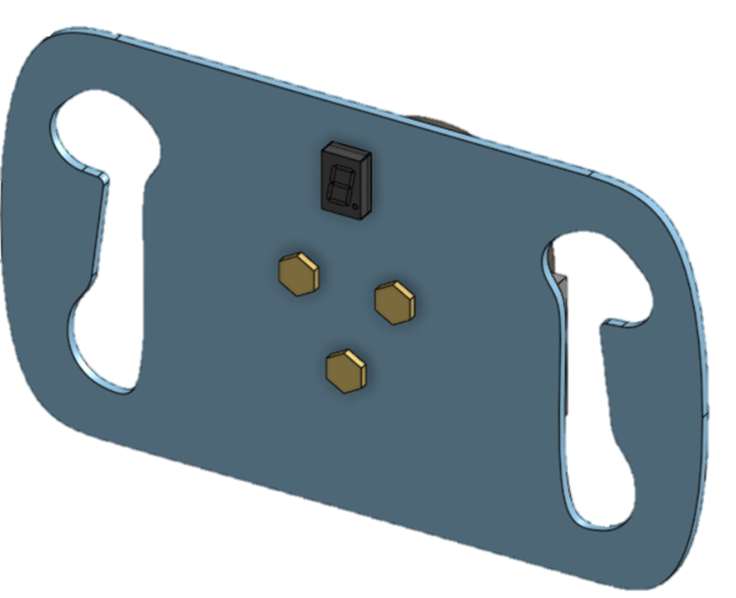
As we are nearing the end of the semester, an update is needed regarding how we used our time from October 27 up until now. Within October 27 and November 9 an iteration of the steering wheel was designed. Inspiration came from an already made steering wheel by FBS Racing Team [Figure 1], their steering wheel has been designed to be as low profile and lightweight as possible. Our design is a heavily modified version that allows space for the attachment of the paddle shifters and a 7 segment display to indicate the gear the car is currently on. The steering wheel is currently being printed to obtain feedback from the Cougar Racing drivers, and to begin to create molds for the grips through the usage of clay and a 3d scanner.
Figure 1: Steering Wheel Sample
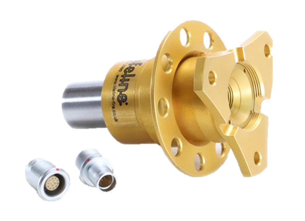
We’ve also researched quick-release kits that have integrated data pins for electronic signals [Figure 3]. 3 data wires are running from an Arduino towards the steering wheel: 2 wires for buttons that are actuated by the paddle shifters and 1 for the gear indicator.
As the piston and pneumatic components are selected, they are being derived onto the Cougar Racing master CAD to explore different placements and start designing mounts for the pneumatic components. [Figure 2]
Figure 2: Pneumatic Components Near Engine
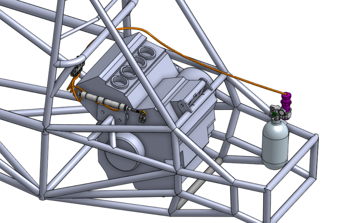
Figure 3: Quick Disconnect for Steering Wheel
To be on track with our capstone and project deadlines, for the work period from November 9th to November 23rd, the team’s plan focuses on finalizing several key design elements following technical analyses. The plan we will work toward is the following:
- Finalizing the CAD Design of the Steering Wheel with Paddle Shifters: We will complete the CAD model for the steering wheel with paddles. This design will be inspired by previous designs but refined through FEA (Finite Element Analysis) in COMSOL or SOLIDWORKS to simulate real-world conditions. Based on FEA results, adjustments will be made to optimize safety factors, including modifying the aluminum thickness and selecting an appropriate grade based on the anticipated radial forces. We will also identify stress points and adjust wall thickness and paddle shape accordingly. Our target is to finalize the CAD and complete the FEA review for this assembly within the November 9th to November 23rd timeframe.
- Selecting Pneumatic Components: The team will evaluate various pneumatic system options to meet performance and cost requirements. With known constraints, such as the force output, total air tank volume, and maximum tank pressure, we will create 3 to 5 system configurations that include a three-position cylinder, solenoid valve, pressure regulator, and tubing. These configurations will be compared based on working pressure, price, volume, and weight, along with an estimate of operational efficiency for at least 60 shifts per minute. By November 16th, we plan to have a finalized selection based on these criteria in a tabulated point system.
- Conducting Thermal Analysis and Insulation Selection: As part of the design process, we will perform a thermal analysis for insulation near the engine area. This analysis will determine the most effective insulation material to manage heat dissipation. By November 23rd, we expect to finalize the insulation choice based on this thermal analysis.
By the end of this work period, our deliverables will include a finalized CAD model for the steering wheel with FEA validation, a selected set of pneumatic components that meet our project constraints, and an insulation material chosen with a cost estimate based on thermal analysis. We will also initiate the programming for an Arduino to activate a solenoid valve as part of the pneumatic system. To provide a better understanding on the proposed system to put together by the end of November, see the figure below.
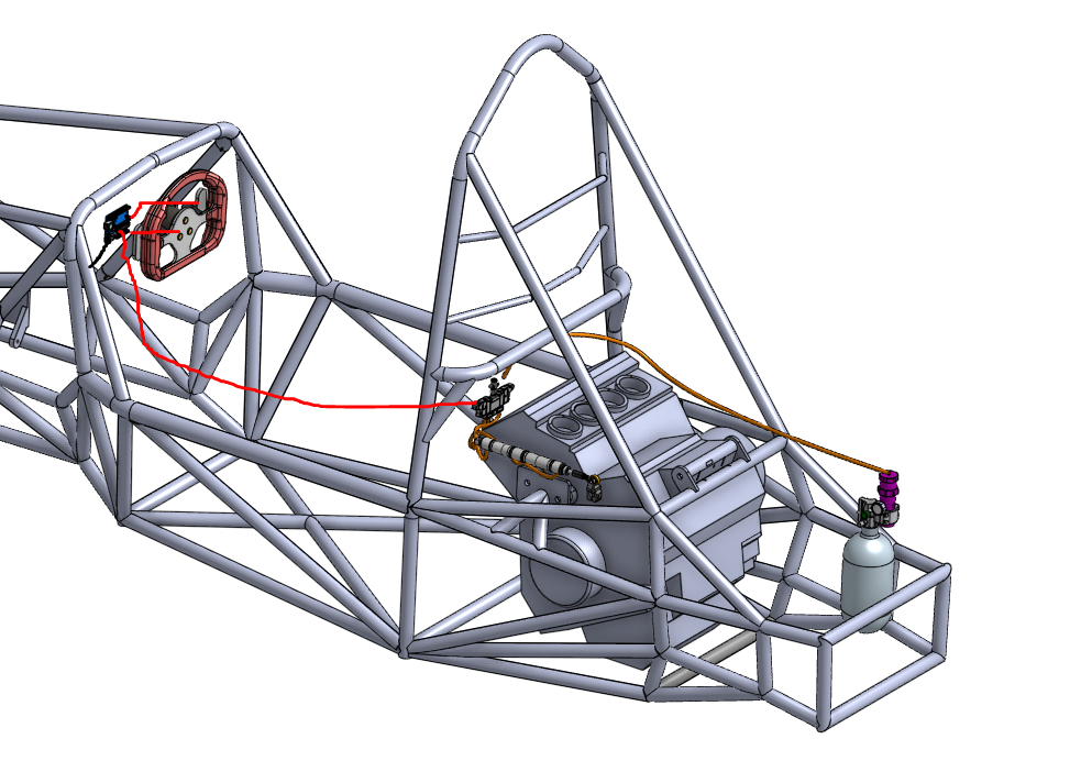
Figure 4: Sample Project Assembly (in progress)
For the work period from November 9th to November 23rd, the team anticipates encountering obstacles related to integrating pneumatic components with the existing FSAE components. Specifically, mounting placements for the pneumatic cylinder, solenoid, and air tank may be challenging due to limited space and FSAE rulebook requirements. To address these issues, close collaboration with the Cougar Racing powertrain team is crucial, as we need to navigate wire routing near the engine gear shifter and clutch. This collaboration will influence the selection and orientation of the pneumatic cylinder.
Another anticipated obstacle is finding a legal placement for the air tank, which currently lacks an approved location. We plan to discuss options with the chassis team, which may involve relocating differential tab mounts, and with the suspension team, which is redesigning the current suspension bridge which can be seen in Figure 5. These adjustments should enable the air tank to be placed safely away from engine heat while remaining within the chassis boundaries as mandated by FSAE rules.
Currently, the car’s engine is undergoing servicing and is expected to be operational by November 17th. Meanwhile, we are coordinating with the powertrain team on potentially running the engine outside the car to collect essential engine data, such as crankshaft position sensor readings and gear position sensor data.
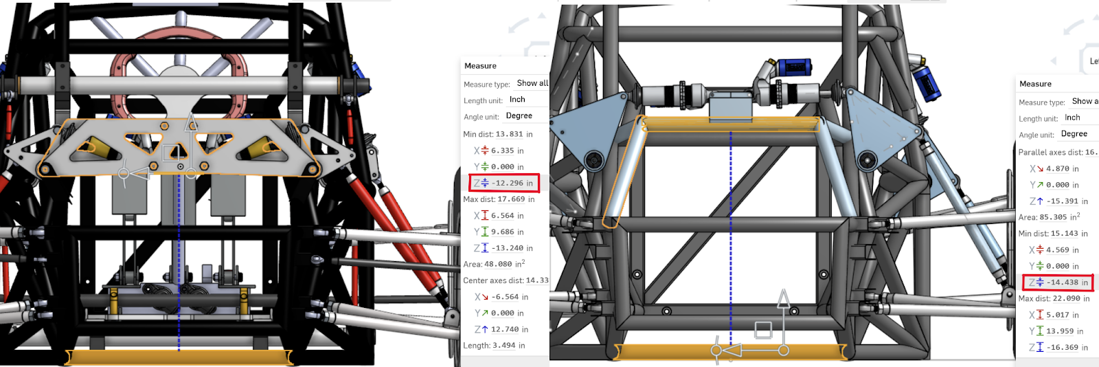
Figure 5: Distance between bottom of the chassis to current suspension bridge (left) vs. proposed future design (right)
Discussions
Become a Hackaday.io Member
Create an account to leave a comment. Already have an account? Log In.