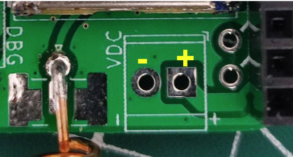
The node is based on an ESP32-S3 PowerFeather, which has extensive power management and monitoring features. It takes care of managing solar & battery power, so that leaves creating the LoRa + GPS wing that can stack on top or below it for this project.
The stacked LoRa + GPS wing and ESP32-S3 PowerFeather is very compact and has all of the power management and monitoring features you could want for potential remote deployments. If you you build this yourself, you should end up with a node that supports:
- Up to 18 V, 2 A solar panel input
- Adjustable solar panel MPP voltage
- Up to 2 A battery charging
- Supply/battery voltage & current measurement
- Fuel gauging (% charge, %health, time-to-full/time-to-empty)
- Battery temperature sensing
- Battery charging current reduction/cutoff based on temperature
- Disabling either GPS and LoRa module for power saving
To get a sense of how small the node is, here it is next to a standard AA battery:
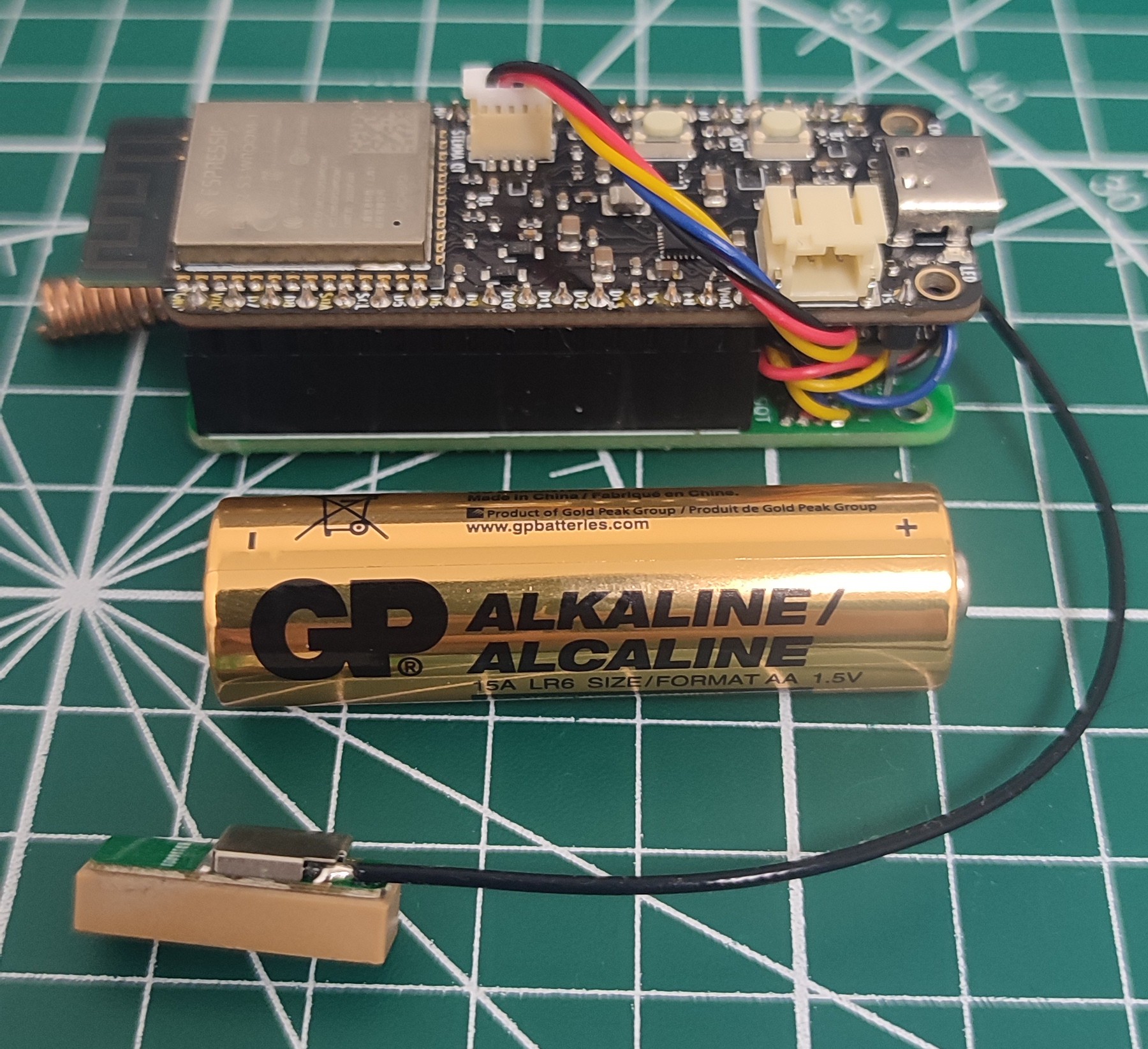
With the power stuff out of the way, let's discuss the LoRa + GPS wing. The wing design has the following features:
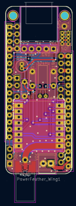
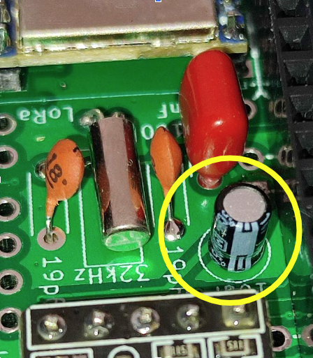
- 32 KHz crystal circuit
This is to support ESP32-S3 BLE modem sleep with light sleep for reducing power consumption (see this GitHub issue for more details). This feature is easy to enable when using ESP-IDF. Unfortunately, it is not enabled in the default ESP32 Arduino library build. You would need to build custom Arduino libraries if you want to use this external crystal circuit with Arduino.
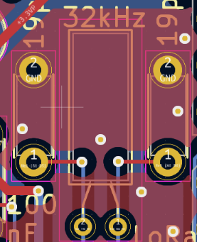
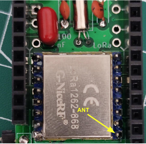
- NiceRF LoRa126X module footprint
This module was chosen since it can be soldered both surface mount or through hole. The design accomodates both.

There are three variants of the Lora126X module depending on the frequency: LoRa1268-433/490, LoRa1262-868 and LoRa1262-915. The footprints are the same for all of them, so use the module with the appropriate frequency for your country.
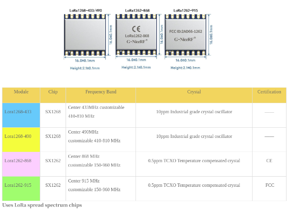
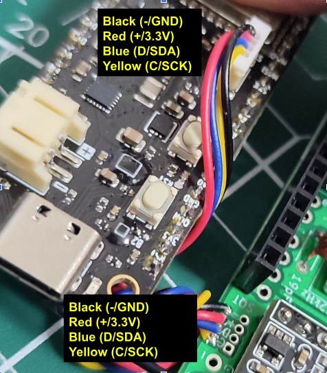
This module is powered from the ESP32-S3 PowerFeather’s STEMMA QT connector 3.3 V output which has a load switch so it can be turned off to save power if necessary
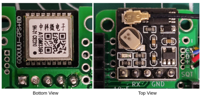
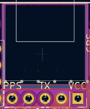
- ATGM336H GPS module footprint
This module is low-cost, has small size and good performance. It's power consumption is a little bit high, though. To address this, this module is powered from the ESP32-S3 PowerFeather’s 3.3 V header output, which also has a load switch. This means it can be turned off when not in use to save power. This is especially handy since the module does not expose the GPS chip’s EN pin.
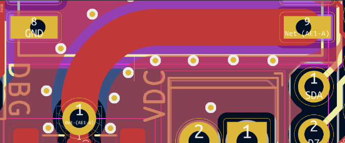
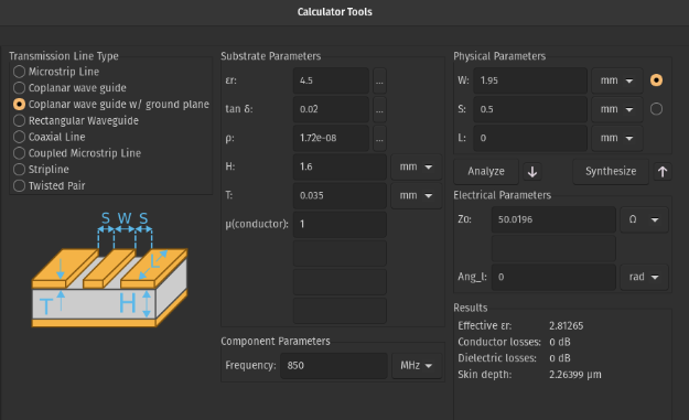
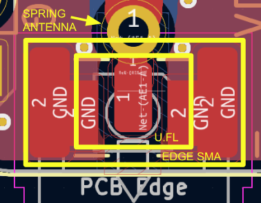
- Combined antenna footprint
Combines footprint for U.FL connector, edge SMA connector and spring antenna so that you can choose whatever suits your enclosure.
 powerfeatherdev