 powerfeatherdev
-
1PCB Fabrication
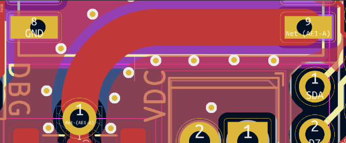
Build the wing using a 2-layer, 1.6 mm thick, FR4, 1-oz copper PCB. If using different PCB thickness, core material or copper thickness, recalculate the antenna feed trace width to achieve ~50 ohms impedance.
![]()
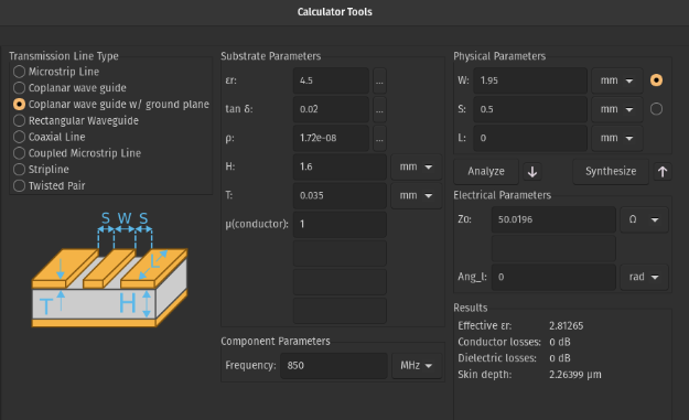
KiCad has a built-in calculator for doing so:
![]()
-
2Component orientation
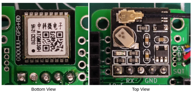
For the GPS module, solder the included 2.54 male headers onto the module. Then, solder the whole module onto the PCB. The metal shielding (the one with the QR code) should be facing towards the bottom of the PCB.
![]()
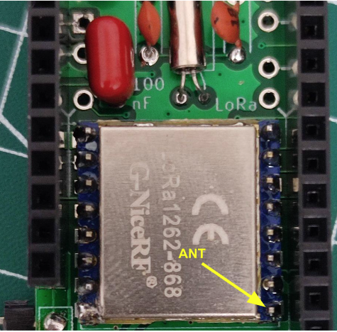
For the LoRa module, if using through hole, solder on 2.0 mm male headers to the module. However, no matter if SMD or through hole, the antenna pin should be on the bottom right corner when soldering to the PCB:
![]()
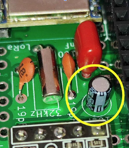
For the electrolytic capacitor, the GND lead should be facing towards the GPS module. In the image below, the white stripe indicates the negative lead for the electrolytic capacitor.
![]()
All other caps (ceramic/tantalum) and the crystal don’t have polarity.
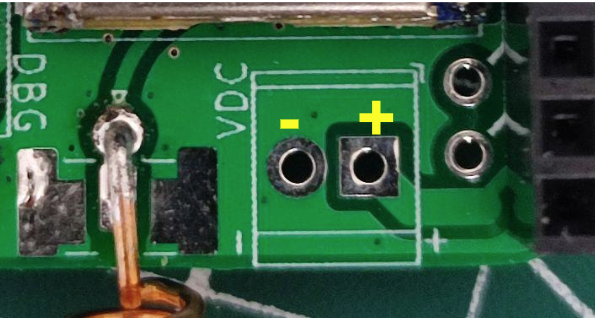
If using the VDC pins for solar panel/DC source, positive is on the right, and GND is on the left (also written on the silkscreen).
![]()
-
3STEMMA QT Cable
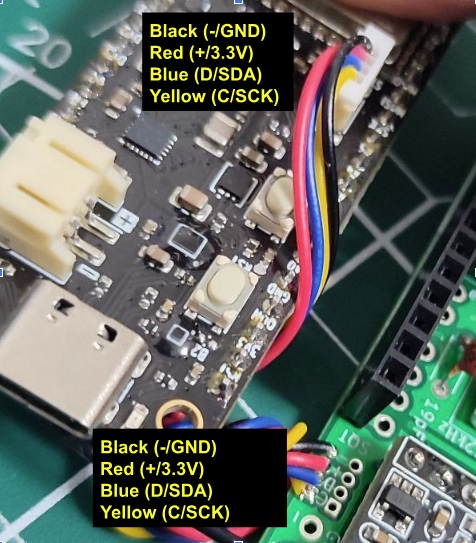
Pay attention to the relative order of the wires to each other when soldering the STEMMA QT cable. My advice is to first insert the STEMMA QT connector into the ESP32-S3 PowerFeather, and then solder the wires on the wing in the same relative order. For example:
![]()
You might get a STEMMA QT cable with different colored wires, or the same colors but different ‘absolute’ order. Make sure however, that the relative order is the same for both the STEMMA QT connector on the main board and soldered wires on the wing.
DIY ESP32 solar LoRa + GPS node
Compact, low-power, solar + battery powered, LoRa + GPS node based on ESP32-S3 PowerFeather
Discussions
Become a Hackaday.io Member
Create an account to leave a comment. Already have an account? Log In.