-
1Unpacking the Kit
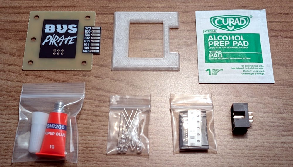
Unless I screwed up, you should have all of the following in your Kit:
![]()
The only difference between the Beginner and Experienced Kits is that the SMD components (the resistors and I/O expander) will be pre-soldered instead of coming in their own bag.
-
2Install SMD Components (Experienced Kits)
If you have the Beginners Kit, you can skip this step. Honestly, if you've got the Experienced Kits you can probably skip this step as well, since you likely know what to do already. But just in case, we'll go over it quickly.
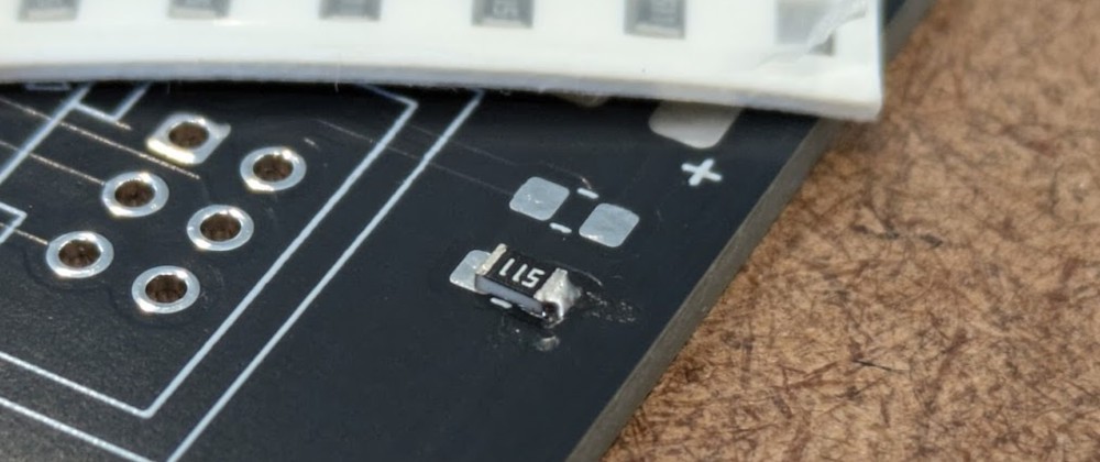
The resistors are easy -- they're all the same value, and the orientation of course doesn't matter. Simply put some solder on one of the pads, position the resistor, and add a little heat to liquefy the solder and tack it down. With the resistor attached on one side, apply some solder to the opposite end.
![]()
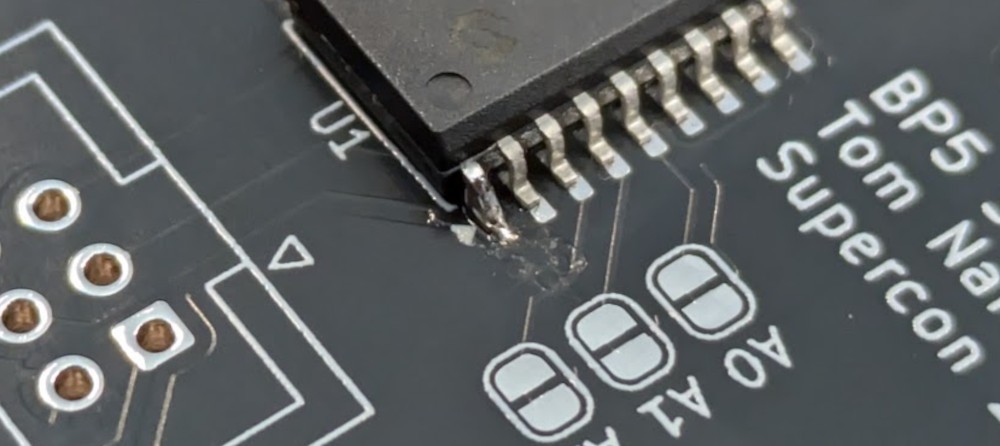
The I/O expander uses the SOIC-18 package, which is a bit harder to hand solder but still fairly forgiving. The trick is to apply solder to one of the pads as you did with the resistor, and use that to tack the chip into position. Make sure you have the mark on the chip (the intended circle) properly oriented with the triangle on the silkscreen -- it should actually be upside-down in relation to the rest of the PCB.
![]()
Once you have one leg soldered down and the rest are lined up, you can run your iron down the length of the chip to solder the rest of the pins. This is a technique known as "drag soldering", and if you can forgive the music, the following video shows the process in detail:
With all the pins soldered down, look closely for any bridged connections. If two pins have a bit of solder connecting them, you can usually fix this by holding the tip of the iron on them for a second or two to melt the bridge. Once all the pins look good, move on to the next step.
-
3Install LEDs
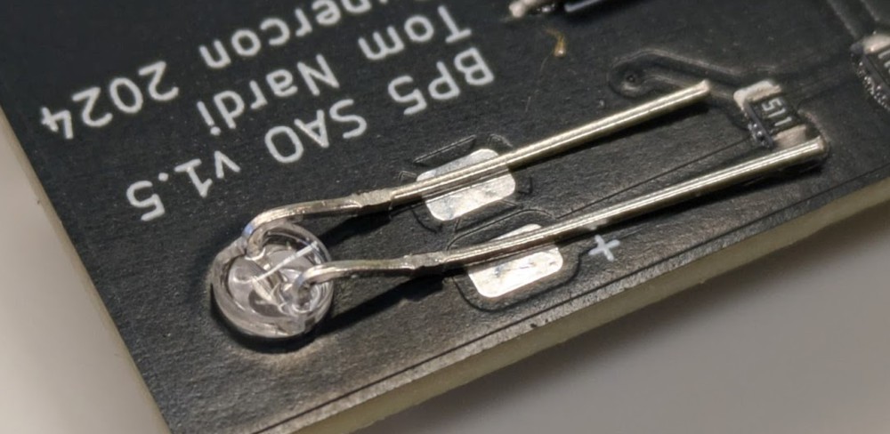
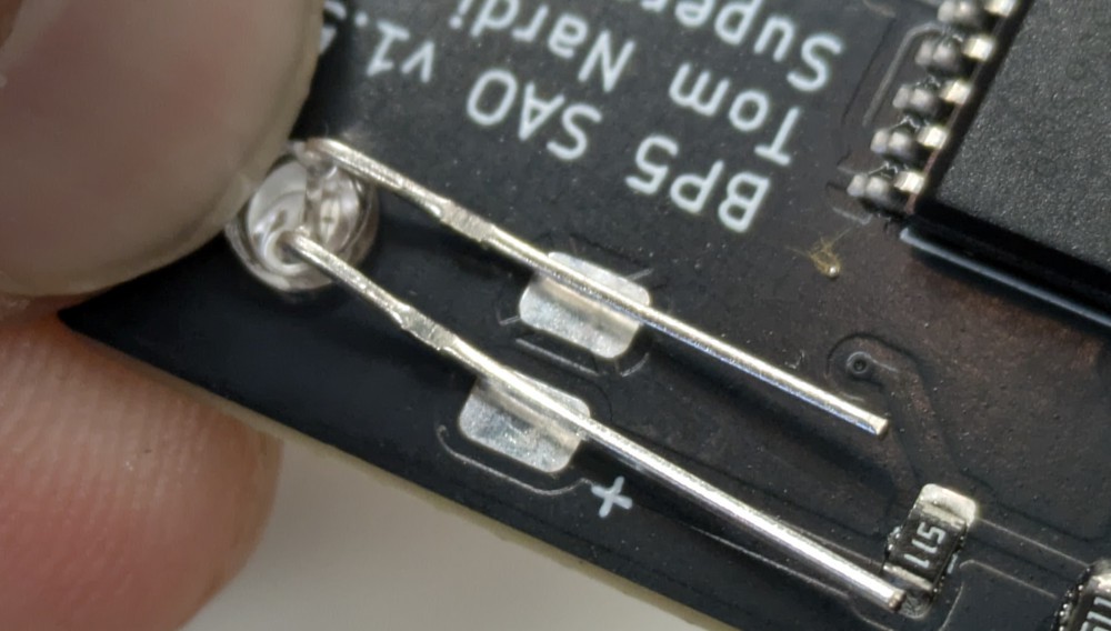
To install the LEDs, insert them into the holes in the PCB and then fold over the leads. Once the leads are flat to the board, you may need to gently spread them apart so they align with the solder pads.
![]()
Note that the orientation of the LEDs is important: the longer led on the LED is the positive terminal, which needs to correspond with the pad marked "+" on the board.
While this is best done with a pair of small pliers, it can be done with your bare hands. In either event, holding down the body of the LED with your thumbnail so it doesn't pop out of the board will allow you to get a better bend.
![]()
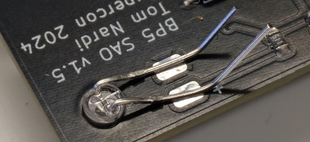
Before soldering the leads to the pads, it helps to bend them upwards to make it easier to cut off the excess
![]()
-
4Solder Connector
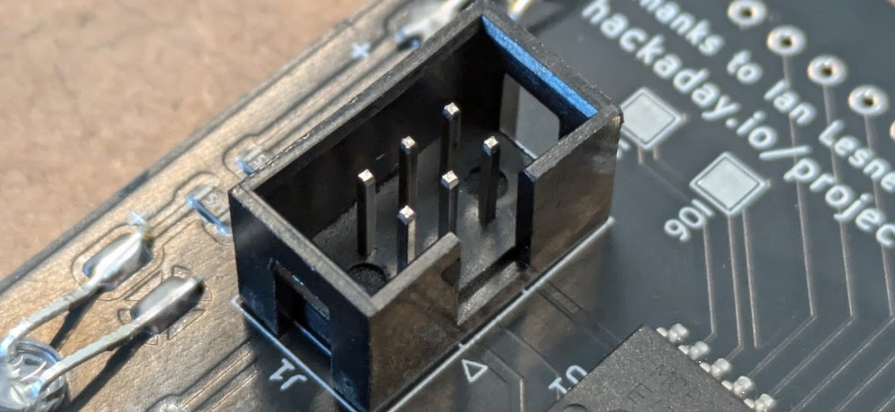
Insert the six pin connector from the back of the board, making sure to align the opening in the shroud with the arrow on the silkscreen so it points upwards.
![]()
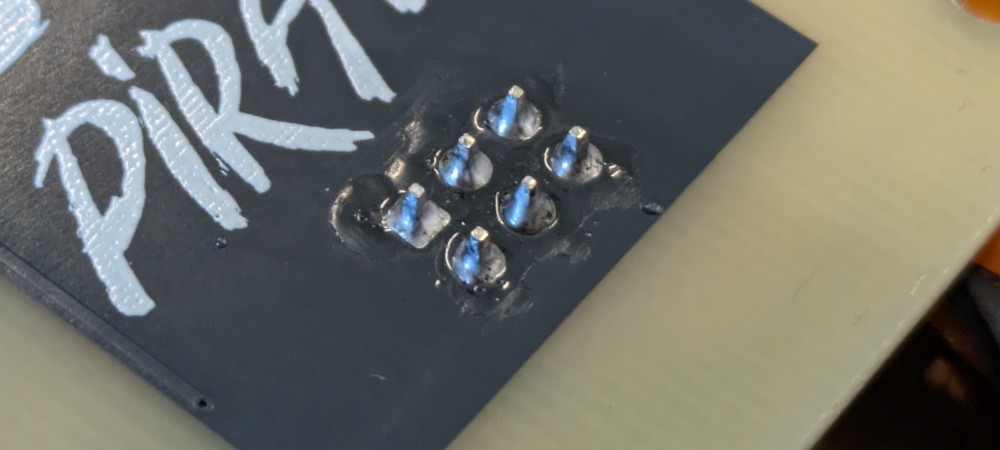
While holding the connector in position (make sure to press it against the PCB), flip over the SAO and solder the pins from the front side.
![]()
Once the connector is attached, you should plug the SAO into your badge to make sure all the LEDs light up. If an LED doesn't light, it almost certainly was connected the wrong way around. Take the time to rework them now, as it will be harder to do once the front plate is glued on.
-
5Glue on Front Panel
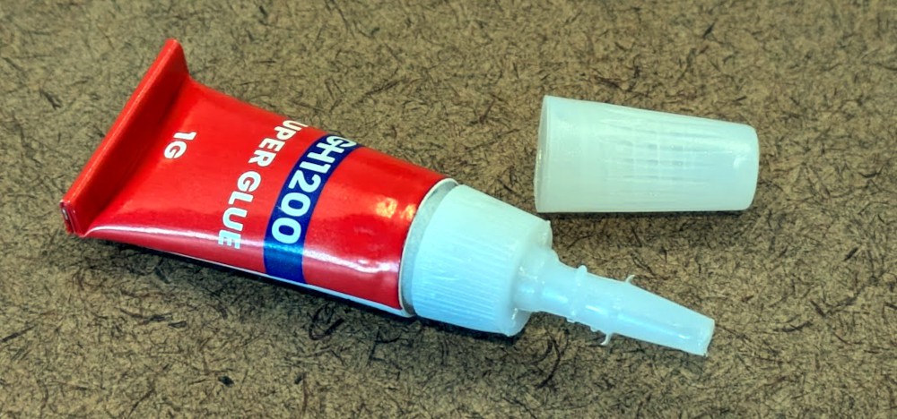
Using the alcohol wipe, clean the front of the PCB to remove any oils from your hands of flux from the solder. While you're waiting for it to dry, attach the nozzle to the tube of glue, and screw it all the way down until it stops. This will puncture the seal on the tube, and you should hear a slight hiss.
![]()
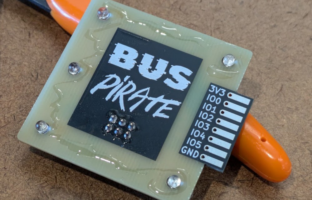
When you're ready, run a thin bead of glue around the LEDs, being careful not to get any on the black soldermask.
![]()
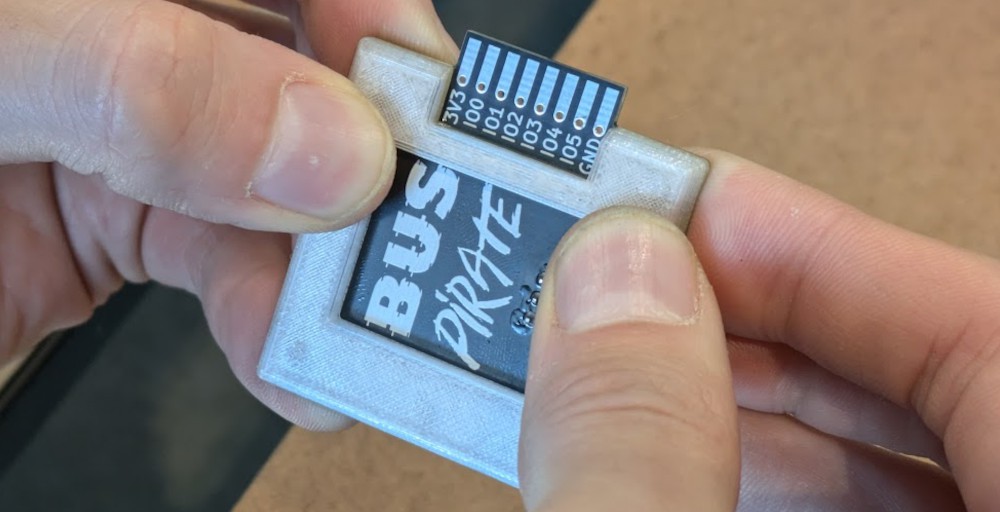
With the glue applied, quickly place the printed front plate on the SAO. The openings in the back of the plate line up with the LEDs, so it should self-center. Once it's down use your thumbs to put pressure on the panel, working your way around the entire SAO while the glue sets up. After 10 to 20 seconds, the bond should be strong enough to let go.
![]()
-
6Run Demo Code
Thanks to the I/O expander you can control each pin on the side of the SAO individually, just like on the real Bus Pirate 5!
This can be easily accomplished by adding the MCP23008 library to the badge file system file system (the MCP library already included on the badge is the wrong one....my bad), and running a few lines of code. The following is a minimal example that will turn on the IO5 pin:
from machine import I2C, Pin
import mcp23008

# Init I2C
i2c = I2C(0, sda=Pin(0), scl=Pin(1))

# Create BP5 device
bp5 = mcp23008.MCP23008(i2c, 0x20)

# Turn on IO5
bp5[5].output(1)
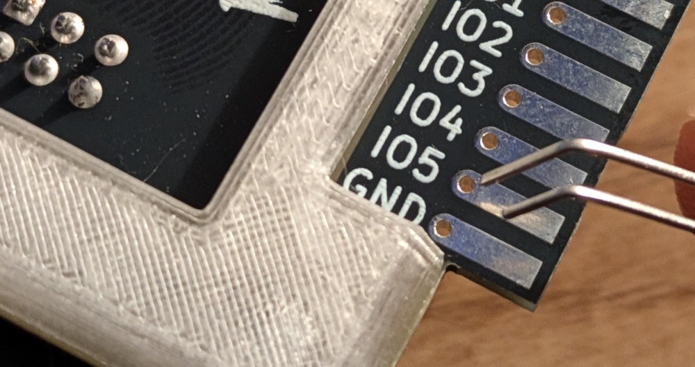
With your spare LED (you didn't lose it, did you?), this can be used to demonstrate functionality of the SAO. Simply insert the LEDs legs into the holes in the side connector (long leg to IO5, and short leg to GND), and fold it over. Once you run the above code, the LED should light up.
![]()
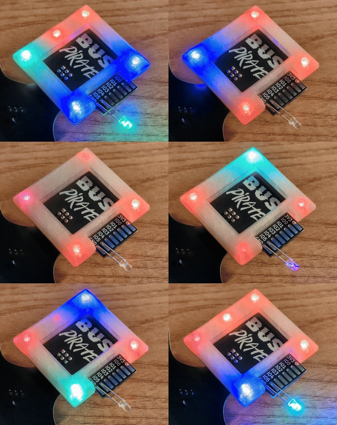
Congratulations, your Bus Pirate 5 SAO is complete! Build something cool, and be sure to show it off.
![]()
 Tom Nardi
Discussions
Become a Hackaday.io Member
Create an account to leave a comment. Already have an account? Log In.