 Larry
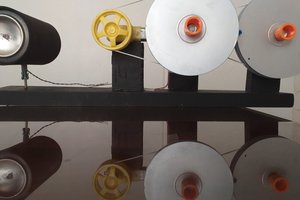
LarryMy robots will use low cost BLDC motors commonly used for drones, RC, and scooters that are high speed and low-ish torque but I will downgear those motors with a Archimedes pulley system that will be custom made from custom fabricated pulleys that will be bearings based. By downgearing with pulleys, instead of gears, I will cut down the noise the robots make so they will be as silent as possible for indoor use. By downgearing, I convert the high speed motors into moderate speeds with great torque. BLDC motors with large torque generally are too large in diameter for a human form factor and take up too much volumetric area to be useful, which is why I go with the high speed smaller diameter type motors but just heavily downgear them 32:1 and 64:1. In my opinion, brushed DC motors are too loud for high quality indoor robotics and way less powerful than an equivalently sized BLDC motor, so I won't be using them at all in my robots.
My robots will have realistic silicone skin. Thom Floutz -LA based painter, sculptor, and make-up artist is my inspiration as it pertains to realistic skin. The skin for my robots has to be at his level to be acceptable. It must be nearly impossible to tell the robot is not human to be acceptable. I will have a wireframe mesh exoskeleton that simulates the volumes and movements of muscle underneath the skin which will give the skin its volumetric form like muscles do. Within these hollow wireframe mesh frameworks will be all the electronics and their cooling systems.
All of my motor controllers will be custom made since I need them VERY small to fit into the confined spaces I have to work with.
I need LOADS of motors to replace every pertinent muscle of the human body in such a way that the robots can move in all the ways humans move and have at least human level strength and speed.
I will have a onboard mini itx gaming PC as the main brains PC of the robot and will have Arduino Megas as the motor controllers and sensor reading devices that interface with the main brains pc. My Arduino Megas will be barebones to keep the volumetric area they take up as small as possible.
0%
0%
My Advanced Realistic Humanoid Robots Project
Building bio inspired realistic looking humanoid robots to do chores and sports and stuff.
Become a Hackaday.io member
Already have an account? Log in.
Just one more thing
To make the experience fit your profile, pick a username and tell us what interests you.
Pick an awesome username
hackaday.io/
Your profile's URL: hackaday.io/username. Max 25 alphanumeric characters.
Pick a few interests
Projects that share your interests
People that share your interests


 César Castillo Andrade
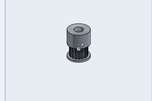
 Michael Sinitsin
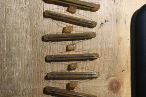
 Mike Rigsby
The robotic arm approach has low feasibility; using artificial muscles offers much greater potential for development.