 Sam Lefebvre
The solution aims to reduce design complexity by abstracting the graphical part from the application part. The graphical layout can be determined by means of a json file and a range of images (bmp/jpg) that are initially loaded from the SD-flash card into an on-board flash chip. The graphical controller can then read-out the chip directly with DMA (Direct Memory Access) to speedup image loading trough SPI-bus. The memory chip is also used to save internal parameters like a pin code or a user setting.
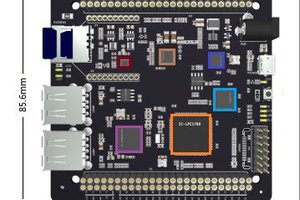
Button actions are predefined as commands and are defined in the json-file. It means that the graphical board also works independently when the interfaces are not the limiting factor. The graphical board has standard 5 digital inputs, 5 digital outputs, a USB-C 2.0 connector and a touch matrix connector. There is also a RTC battery and a 24bit TFT RGB connector with touch controller interfaces for capacitive and resistive touch panels. Next to the graphical controller, there is a STM-32U575 processor that is programmed trough an SWD-connector thats connects to a ST-Link V2 programmer. An internal boot loader enables programming over USB without using the programmer.
On the board there is also an auditive piëzo buzzer and a graphical font-chip that contains character maps for more than 150 languages. The power supply creates a stable internal 5VDC rail for its internals and the add-on board. A PWM-driver enables backlight dimming in the full range. The I/O voltage range is configurable by jumpers.
A red case has been 3D-printed with PLA that fits both boards to show the housing posibilities. It delivers a console that could be wall-mounted for applications in buildings, automotive environments or green-houses.
 Plasmode
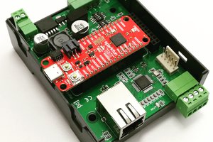
 Gergely Imreh