1-Project Objectives
- Enable users to remotely control an RC car from a custom-built web page.
- Stream real-time video from the car’s perspective to the same interface.
- Integrate an interactive panda coin collector mechanism.
- Utilize affordable components to create a functional, engaging system.
2-System Architecture and Design
System Overview
- ESP32-CAM: Hosts the web server, handles video streaming, and transmits control commands to the second ESP32.
- Second ESP32: Receives commands, controls motors via the L298N, and operates the servo motor for the panda box.
- Web Interface: Displays the video feed and provides a control panel for the RC car.
Block Diagram
- ESP32-CAM: Captures video, hosts the web server, and transmits movement commands.
- Second ESP32: Controls motor driver and servo motor based on commands.
- Web Interface: Integrates video streaming and control functionality.
3-Wiring Details
- ESP32-CAM and Second ESP32:
- GPIO 3 (TX) of the ESP32-CAM is connected to GPIO 16 (RX) of the second ESP32 for serial communication.
- Both modules share a common ground.
- Motor Driver:
- The second ESP32 controls the L298N motor driver, which powers the car’s motors.
- Servo Motor:
- Connected to GPIO 12 of the second ESP32 for controlling the panda box.
- Push Button:
- Connected to GPIO 13 and ground on the second ESP32, serving as the trigger for the panda box.
Step-by-Step Build Guide
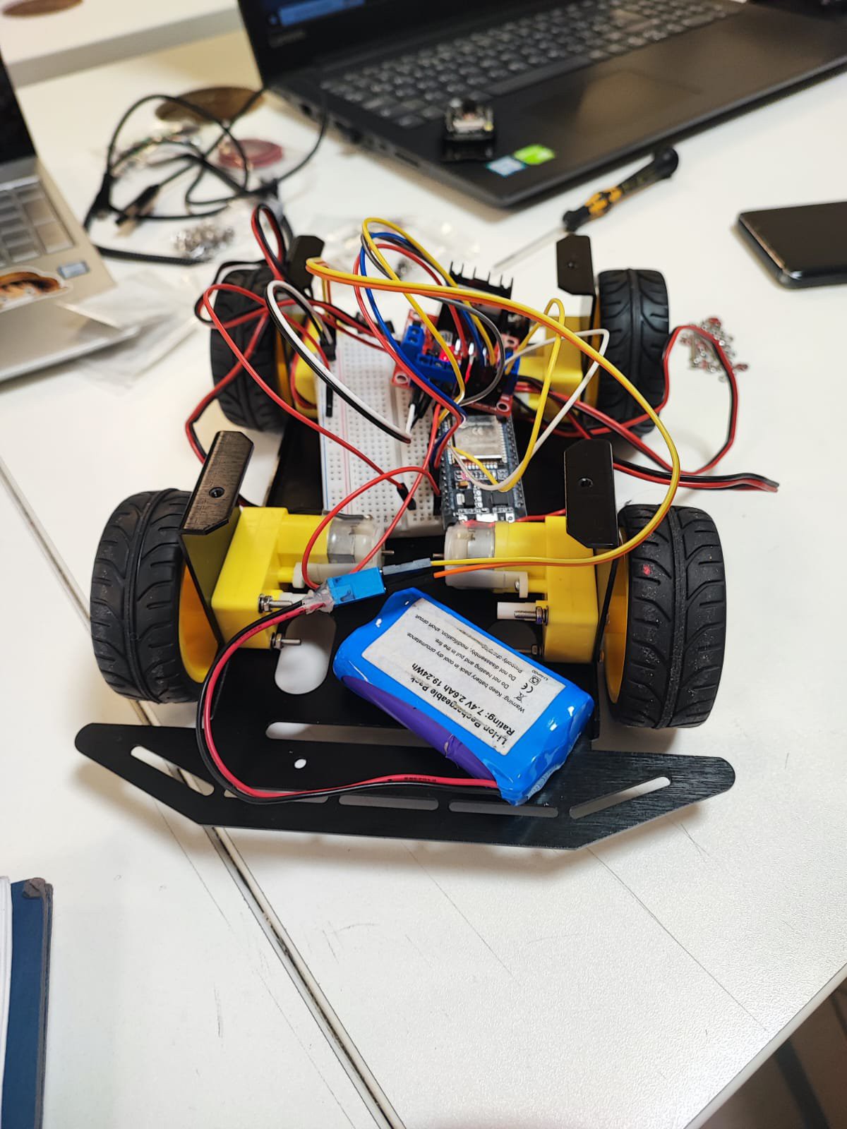
- Assemble the Chassis:
- Attach wheels, motors, and other hardware to form the car’s base.
- Set Up the ESP32-CAM:
- Connect the ESP32-CAM to a breadboard.
- Program it to stream video and transmit movement commands via UART.
- Connect the Motor Driver:
- Wire the L298N motor driver to the motors and the second ESP32.
- Test connections to ensure proper control of directional movement.
- Integrate the Servo Motor:
- Connect the servo motor to GPIO 12 of the second ESP32.
- Program the servo to respond to the button on GPIO 13.
- Build the Web Interface:
- Develop an HTML/CSS/JS webpage to stream video and provide control buttons.
- Test communication between the web interface and the ESP32-CAM.
- Test and Troubleshoot:
- Verify seamless communication between both ESP32 modules.
- Test motor control and panda coin collector functionality.
How It Works
The RC car leverages two ESP32 modules to separate tasks and optimize functionality:
-
Web Server and Video Streaming:
- An ESP32-CAM hosts a web server using mobile data from a cellphone.
- The server's webpage, developed with HTML, CSS, and JavaScript, displays the live video feed from the ESP32-CAM’s camera and includes control buttons for the car’s movement (Forward, Backward, Left, Right, and Stop).
- Button handlers send commands directly to the ESP32-CAM’s serial port, which communicates with the second ESP32.
-
Motor Control:
- Due to limited GPIO availability on the ESP32-CAM (some pins are internally used by the camera module), motor control commands are forwarded via UART to a second ESP32.
- The ESP32-CAM’s UART outputs commands like "Forward" to the second ESP32, which reads the input and triggers the motor driver to execute the corresponding movement.
-
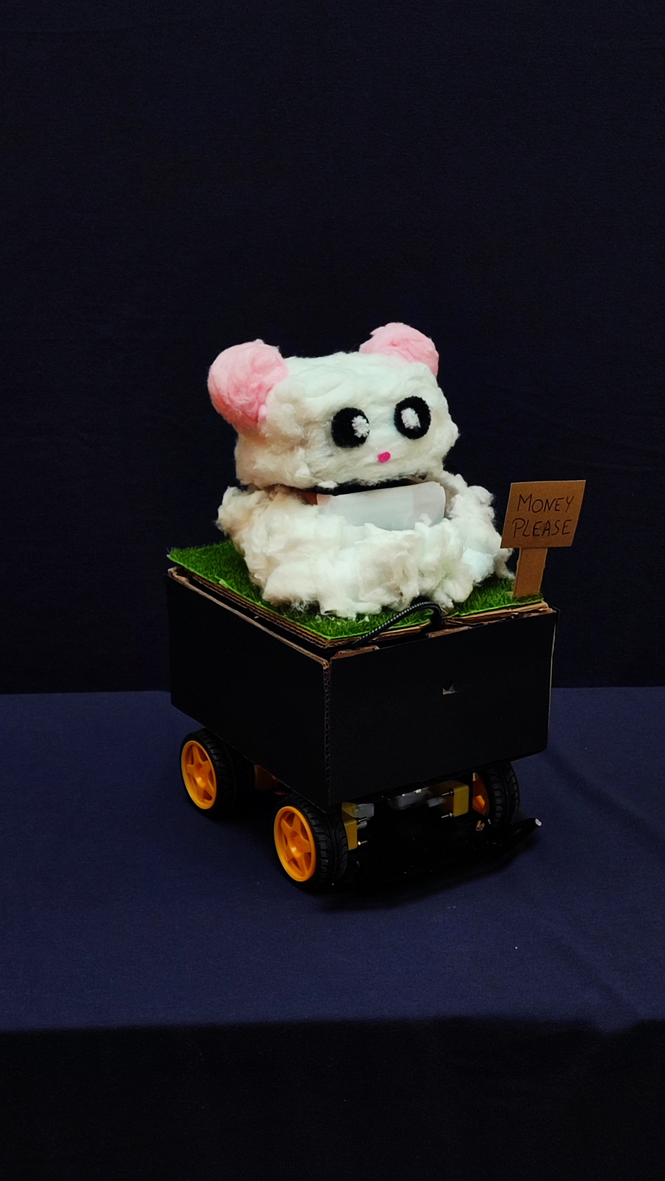
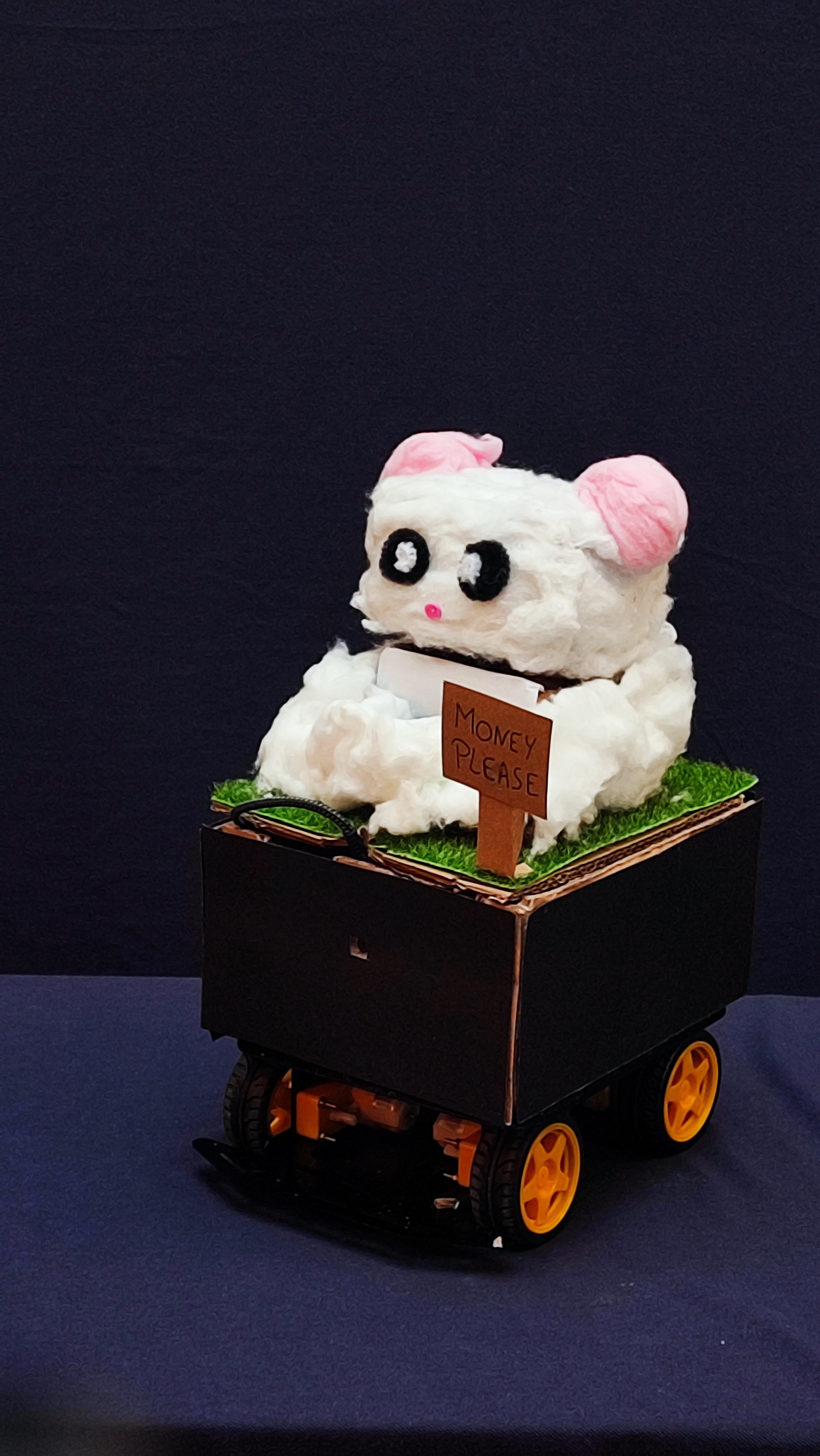
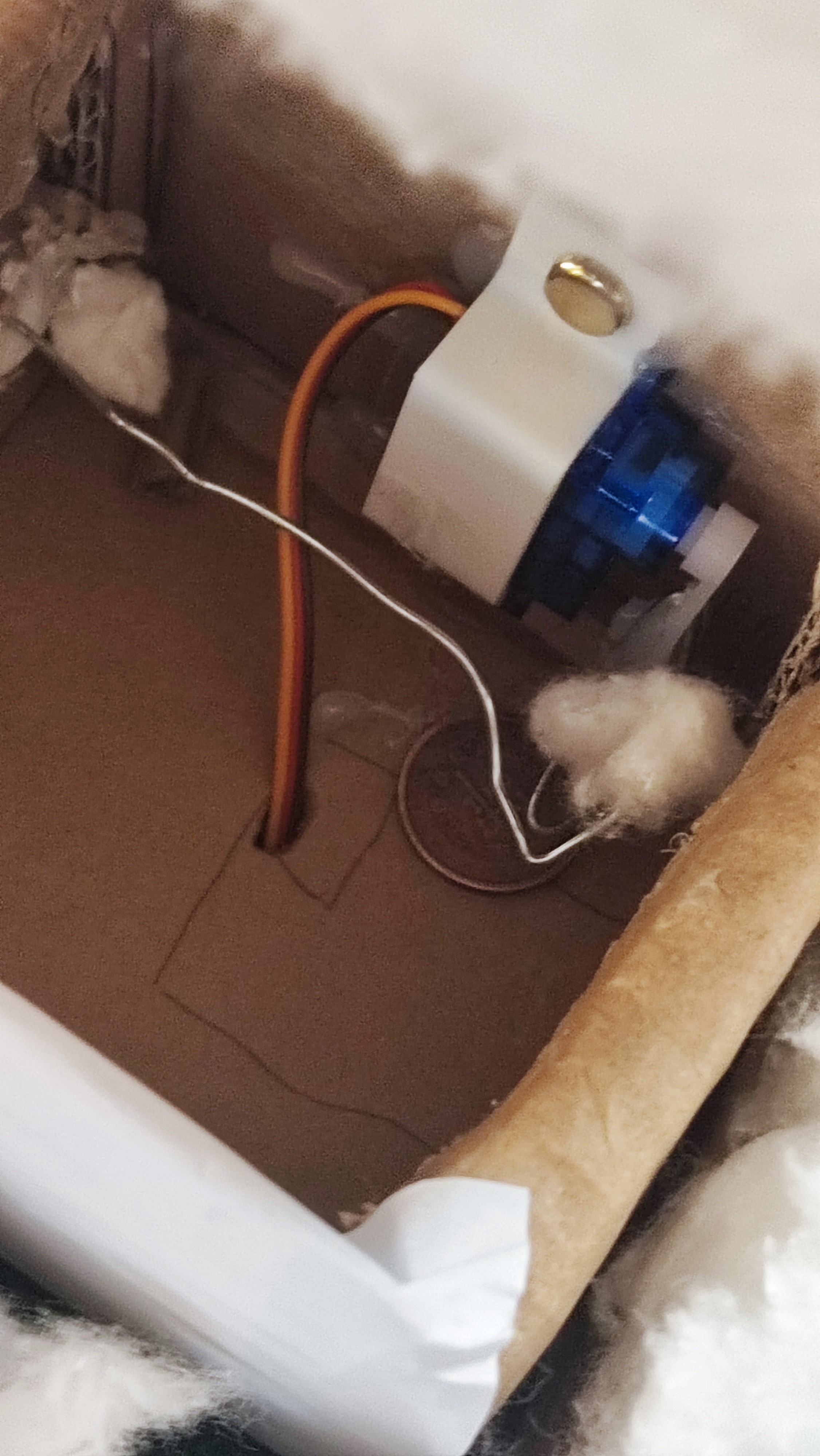
Servo-Controlled Panda Coin Collector:
- A servo motor connected to the second ESP32 controls the panda box.
- When a button connected to the second ESP32 is pressed, the servo motor opens the panda box lid, accepts the coin, deposits it, and closes the lid.
- The second ESP32 uses the millis() function to ensure non-blocking control of both the motor driver and servo motor, avoiding conflicts between PWM signals.