 debraansell
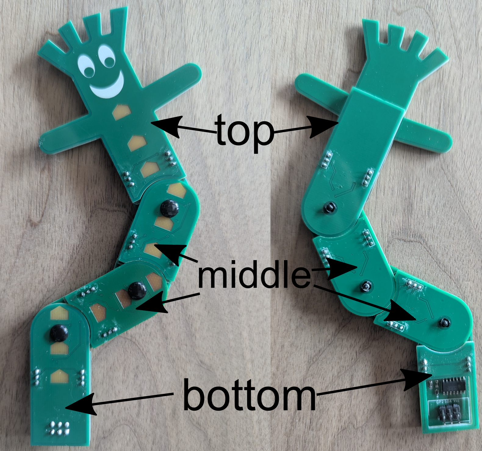
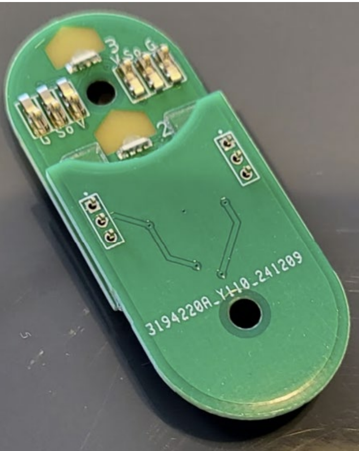
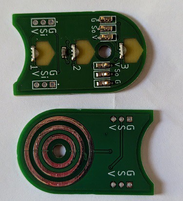
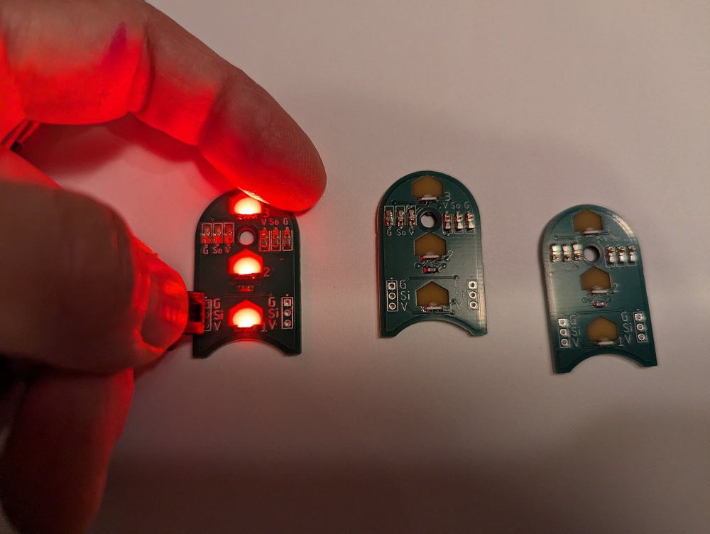
This design is a flexible assembly comprised of two layers of PCBs which can pivot while maintaining electrical contact through spring-loaded pressure connectors on one side and circular contact pads on the other. It's basically an assembly of PCB slip-rings, with addressable LEDs that will display animation patterns along the full length of the assembly, no matter how the constituent boards pivot and bend.
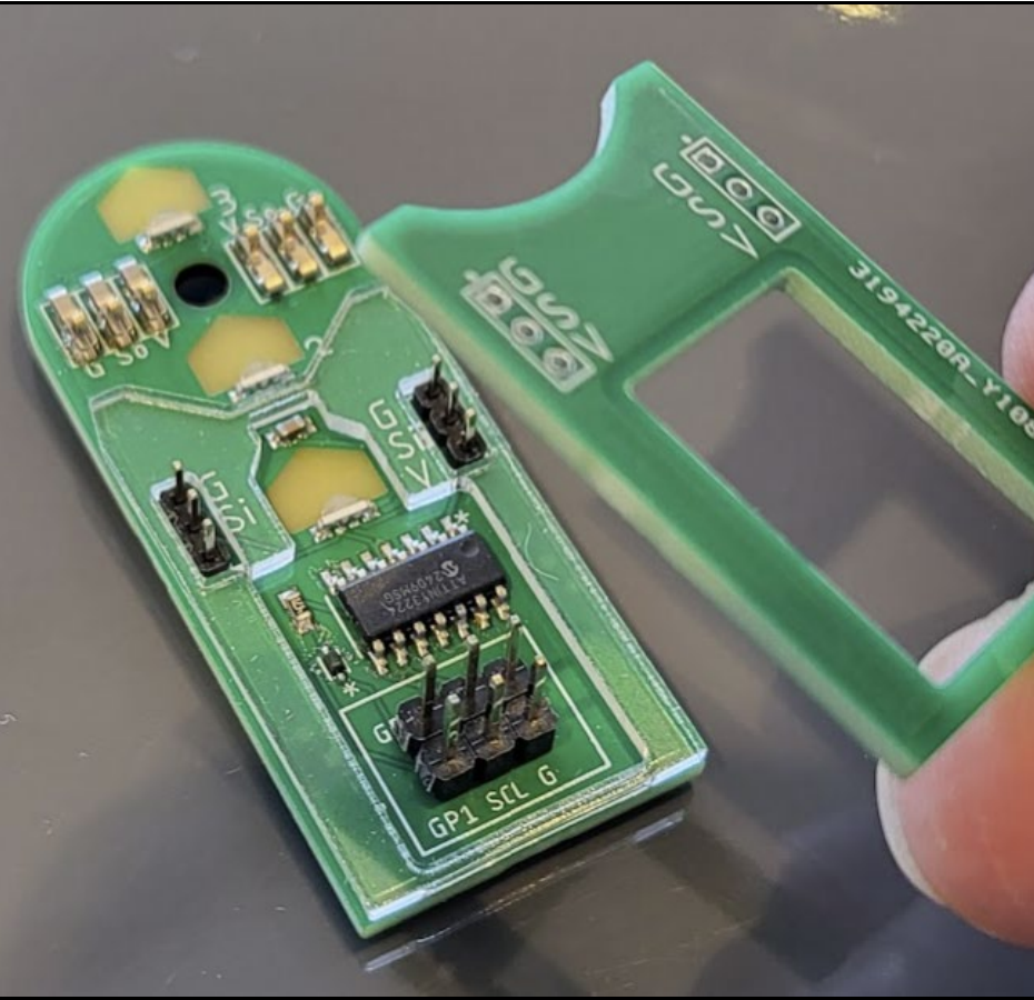
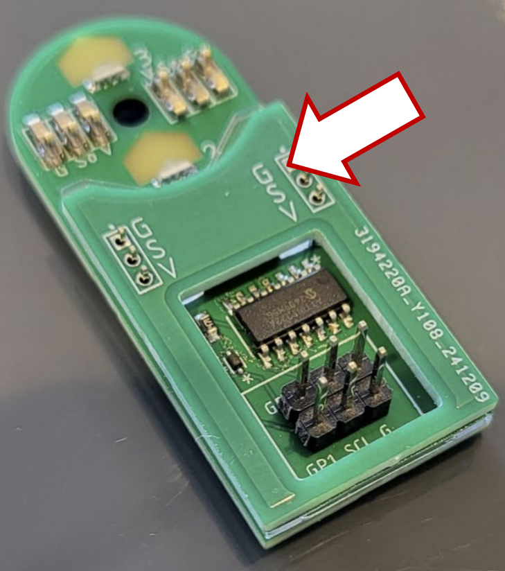
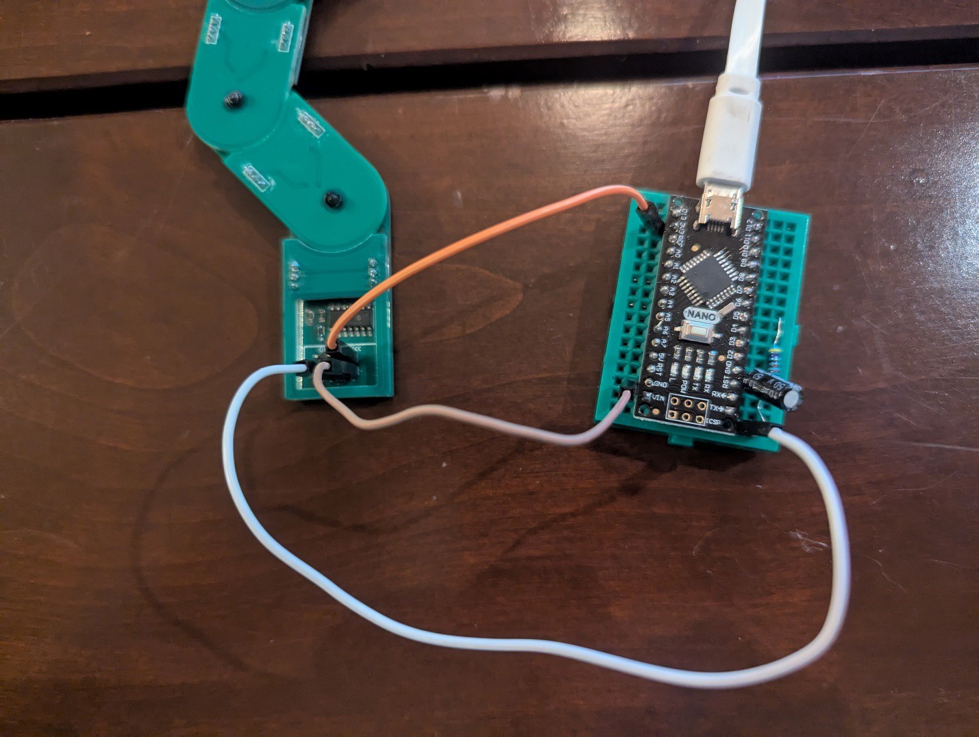
The SAO can work with *either* a badge communicating through the SAO connector on the back, or with a XIAO/QTPy or other pin-compatible microcontroller through a connector on the front side. The SAO connector provides Gnd, VCC, Signal (Through GPIO1) to control the twelve WS2812 compatible LEDs. An attached XIAO board can control the Bendy SAO through Pin D2 (RP2040 GPIO28) and provide power through the USB C port.
Micropython code for a badge or XIAO is available at https://github.com/geekmomprojects/BendySAO/tree/main/code/BADGE_micropython
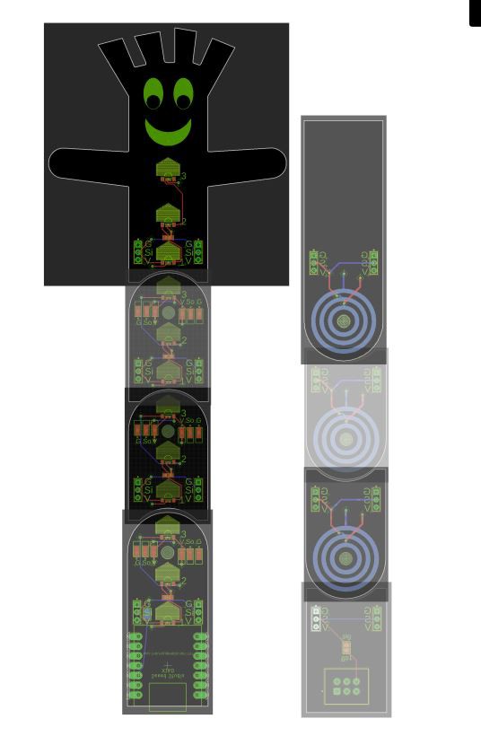
I built a successful proof-of-concept a few years back: https://github.com/geekmomprojects/ArticulatedPCBs, but wanted to try to make it more fun this time, so the assembly of boards now takes the shape of an inflatable car wash balloon man, and the LEDs are mounted inside the assembly, to illuminate it from the inside.


 Arnov Sharma
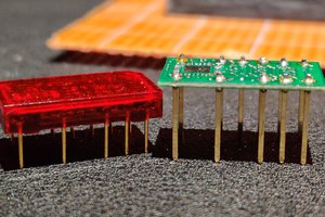
 Jacob Still
 DIY GUY Chris
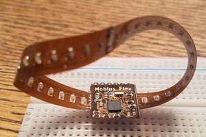
 Chris Miller
Very cool! Video please, for those of us unable to make SuperCon... :)