 Luicer's Lab
Introduction
Following the design of a linear driver Link, this article presents a design of a switching driver for a commercial LED flashlight, specifically the Ultrafire DV-S9 diving light. This design aims to achieve higher efficiency, thereby better utilizing battery energy. Se more in: https://luicer.github.io/led%20flashlight/Flashlight-Driver-Switching-Eng/

Driver Specifications
The designed driver features:
- Switching regulator type.
- Adjustable current up to 1 A.
- Input voltage from 3 V to 4.2 V.
- Standby current of 4 mA.
Block Diagram
The proposed design’s block diagram is as follows:

The driver design utilizes a DC/DC step-down regulator with current sensing to measure the supplied current to the LED. A DC/DC regulator enable pin is used to turn the system on or off.
Schematic
The schematic used to implement the design is as follows:

This schematic can be downloaded here.
PCB
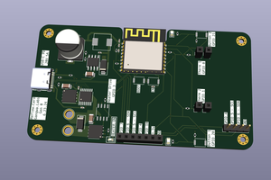
A double-sided PCB has been designed to fit into the commercial flashlight casing and be easily replaceable. Consideration has been given to track currents and EMI control rules to ensure reliable current measurement with a small current measuring resistor and minimize PWM track surfaces to avoid disturbance emissions.


The assembled PCB looks as follows:

The Github repository includes Gerber files for manufacturing generated for the PCB manufacturer JLCPCB, compatible with most PCB manufacturing houses.
BOM
The list of required materials is as follows, including LCSC component codes.

At the time of writing this post, the component cost for manufacturing 10 units on the LCSC website is $23.13. Therefore, the component cost per unit would be approximately $2.313.
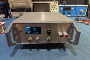
Measurements
The current measured from the voltage across the 10mΩ resistor with the oscilloscope is as follows:

Channel 1 measures the current supplied to the LED, taking into account the measurement error (approximately 2mV), the current is 1A with a ripple of 350mA. The current does not pass through 0, thus avoiding flickering. Channel 2 measures the feedback voltage, which is 600mV as indicated in the DC/DC regulator datasheet, but oscillations causing the measured ripple are also observed.
Efficiency and Operating Voltage Measurement
With the aim of obtaining the efficiency of the driver, measurements were taken by varying the input voltage between 2.9 V and 4.2 V, measuring the input and output voltage and current.
The output current as a function of the input current:

The efficiency as a function of the input current:

It confirms that the flashlight is usable from 3 V to 4.2 V with a consistent efficiency of approximately 85%.
Design Documentation and License
All design documentation, including the KICAD PCB project, manufacturing documents, schematic, and bill of materials, are available in the following Github repository:
https://github.com/luicer/Switching-Flashlight-DV-S9-Driver
This design is open source hardware under the permissive CERN OHL V2 license.
 Gangwa Labs
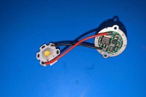
 Mario Ninic
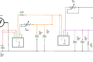
 MrWunderbar