I did a writeup for the motivation for this design over here, but the end result is that I wanted to put as many wavelengths of LED as I could onto a CIE 1931-shaped badge.
The first challenge was finding all the LEDs needed for this. Because this was in a SAO form factor, I was limited to using small 0603 or 0805 LEDs instead of the big, powerful Chip on Board LEDs. This means all the LEDs will have to come from the "Indicator LED" section on Digikey where there is generally less selection of color -- who cares if your indicator light is a slightly deeper shade of red than a standard 615nm red? A bit of a challenge, but I managed to find 12 unique colors plus four shades of white for a total of 16 LEDs:
| Color Name | Wavelength (nm) | v1 P/N |
|---|---|---|
| UV | 456 | 150224BS73100 |
| Deep Blue | 465 | APT2012QBC/D |
| Blue | 470 | QBLP631-IB |
| Teal | 496 | SMLD12E3N1WT86 |
| Emerald | 505 | SMLD12E2N1WT86 |
| Green | 525 | QBLP631-IG |
| Yellow-Greener | 560 | SML-M13PTT86 |
| Yellow-Green | 570 | QBLP631-AG |
| Yellow | 590 | QBLP631-Y |
| Amber | 605 | QBLP631-O |
| Red | 625 | QBLP631-R |
| Deep Red | 640 | QBLP631-S3 |
| Soft White | 3000K | QBLP675-IW-WW |
| Cool White | 4000K | QBLP675-IW-NW |
| Bright White | 6000K | QBLP675-IW-CW |
| Daylight | 11000K | QBLP661-IW5-CW |
I think my favorite are the Teal and Emerald LEDs from Rohm: they're marketed as being indicator lights for color universal design to make indicators apparent for colorblind folks. Pretty neat!
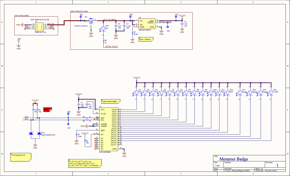
Of course, with all these LEDs comes a requirement to control them. Since the goal of the design is to show off how color mixing works, intensity control of each individual LED is required. Ideally the badge will be able to control the SAO, so I opted to use the SAO-spec standard I2C interface connected to a driver chip of some sort. I looked through a bunch of driver ICs and eventually settled on the LP5018RSMR constant current LED driver. This chip has a few advantages: first, controllable over I2C. It's designed for controlling RGB LEDs, but allows you to control each individual channel just fine which is what I'll be using. Additionally, it uses constant current control, which means I don't need a separate current-limiting resistor per LED -- reducing the amount of soldering and making layout easier. Finally, it's not a matrix-style controller, so all I need to do is provide power to the anode and route the cathode to the IC, again making layout easier.
I wanted the badge to not only work well but also look nice, which led to the decision to only do bottom-layer routing. I wanted the top layer to only have LEDs and silkscreen for a cleaner look, which made this IC even more useful as it greatly simplified single-layer routing.
All that's left is a bit of power protection to prevent reverse voltage (using a PMOS reverse polarity circuit) and prevent overcurrent from damaging the host badge (using the AP22653AW6-7 current limiting power switch) and we're good to go!

Because I love being difficult, I wanted to do any-angle routing + curves for the entire board to embrace the non-rectangular nature of the CIE1931 horseshoe. Lovely idea in concept, complete pain in practice. Altium is already iffy with any-angle routing, and the moment you try to throw curves in there it gets rather nasty. Thankfully there were not too many traces to have to coax into the right place, and the end result is appropriately swirly.
 Reid Sox-Harris
Discussions
Become a Hackaday.io Member
Create an account to leave a comment. Already have an account? Log In.