Close
0%
0%

Metamer SAO

You’ve heard of RGB, now get ready for RRAYLLGTTBB+UV+WWCWBWDW

Similar projects worth following
A SAO with all the LEDs to explain how metamerism works! Instead of simple RGB color mixing, this thing can mix-n-match 16 unique spectra to make that perfect color you've been looking for.

Features

  • 12 unique wavelengths of LED + 4 temperatures of white
    • Includes a really cool 505nm LED which is a color coming from an LED you've probably never seen before
  • I2C brightness control
  • [coming soon] No badge needed: onboard MCU!
  • Probably won't overcurrent your badge
  • Eventually cool color mixing tricks. Currently very good at turning on and looking pretty.
  • If colors aren't your thing, I've been told the shape looks like a Star Trek badge or half of a pair of furry ears
  • Impossible to photograph properly, since cameras and monitors can't reproduce its range of colors

Using It

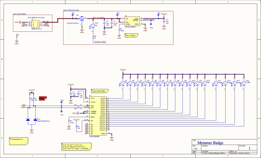
The heart of the SAO is the LP5018, an RGB LED driver from TI. Accessible over the SAO I2C bus at address 0b0101000, the first 16 channels correspond to all of the LEDs in increasing wavelength (i.e. blue to red) followed by the white LEDs from warm to cool. Schematics and board files available over on GitHub along with some generator code, and soon-to-be instructions on how to talk with it yourself.

Metamers?

Metamers are a really neat concept where our eyes only have three channels worth of detection, corresponding to the short, medium, and long cones in our eyes. As a result, two different spectra of light will look the same to our eyes if they happen to stimulate the three types of cones in the same way -- this is part of how a computer screen is able to reproduce all of the complex colors that we see in the real world. I go into a lot more depth (including answering "why even care?") over here. TL;DR, colors are cool, the way eyes interact with colors is cool, and RGB isn't the end-all and be-all of color mixing.

  • v2: Hackaday Supercon

    Reid Sox-Harris10/13/2024 at 19:12 0 comments

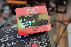
    A few months later, and it's Supercon time! There were a few flaws I wanted to fix from v1 to make it able to be given out to other folks and generally a more interesting board to work with. 

    First up: bootstrapping I2C. The default state of the LED controller is all off, which generally is probably a good thing. Unfortunately, that means you need to sent I2C commands to the SAO if you want it to do, well, anything, which makes it hard to give to other people. Having to entirely reflash a badge with custom firmware (that would overwrite your custom firmware) is generally a non-starter, so that had to change. 

    I swear at some point I found a RGB LED controller similar to the LP5018RSMR, but with flash memory to save a default state. That would have been perfect! Unfortunately, after a few hours of searching every LED driver manufacturer I could think of, this might have been a 2am hallucination after all. Ok, so if the LED driver can't save state, then what else can I do? 

    A few years ago, I came across Jay Carlson's $1 microcontroller roundup, filled with cheap MCUs of every size, shape, and flavor. A whole dollar felt a bit much to send a few I2C commands and then lay dormant, so I then came across his $0.03 MCU review. Ok, getting closer, but having a OTP MCU feels a little risky for me, and also makes it rather unhackable down the road. Thankfully, there's a middle ground: a $0.11 flash-based MCU! Nice and cheap, reprogrammable, and seemingly very well-featured for the price. So, this got designed in fairly easily, and will be programmed to initialize the LED driver on power-up so that the SAO will actually display something, even on a default badge without custom firmware. Plus, down the line I can perhaps offload animations and such to this MCU instead of doing it on the badge itself. A lot of opportunity for not a lot of cost. Adding that MCU was fairly painless (though beware, the location of the debug pins changes depending on if you're looking at the English datasheet or the Chinese one, trust the more up-to-date Chinese one), resulting in the v2 schematic: 

    Problem number 2: the cost. I want to make a good number of these to give out, I don't want to take out a loan for it. The BOM for v1 came out to a tolerable $4.38CAD per bare board plus controller and power protection... and an eye-watering $10.33CAD for all of the LEDs! Part of the issue was that I was ordering in single quantities, part of the issue is that some of the LEDs were just too esoteric for normal pricing, but in any event, I needed to take the unit cost down from $15CAD/board. 

    The lowest hanging fruit was alternate sourcing for the LEDs. Digikey is great for next day shipping and consistent quality, but you do pay a price for that. For bulk(ish) LEDs for a large build, LCSC provided much, much, much better pricing, with the caveat of taking longer to ship all the way from China, and ordering parts from brands that I've never heard of before. For just a fun little demo board though, no problem. The updated BOM is in the Github repo, but I was able to get the cost down to just about $1.10CAD for all of the LEDs, though I had to drop the 496nm LED. It's so cool, but the 505nm is close enough and it saves $1.17CAD -- it's cool but not the-entire-cost-of-all-the-other-LEDs-cool. The 505nm is still the most expensive LED at $0.56/ea @ 100, but I had to include one of the weird LEDs one way or another. I also did a few other subs such as making the UV led truly UV instead of just very deep blue (it's UV-A, it's safe, don't worry) and a few others are +/- 5nm or so, but overall the 10x cost saving is absolutely worth it. 

    The final problem was assembly time. Manually soldering the two dozen or so components on the back is fine for one or two boards, but will suck up a lot of time for 20. Thankfully, JLCPCB also has stupidly cheap assembly services. This did require a few more BOM adjustments to get all the components into...

    Read more »

  • v1 Build

    Reid Sox-Harris10/13/2024 at 18:18 0 comments

    This SAO was originally designed to bring to the Open Hardware Summit 2024 in Montreal, Canada. They hinted at the possibility of a SAO connector on the badge pretty close to the summit date, so it was a bit of a scramble to get this designed and fabbed in time. I went with JLCPCB to fab it, which meant 3ish days in production + about a week to ship + a day or two to assemble... rather tight, but doable. Unfortunately this meant having to comprimise on build quality: I wanted a white soldermask and ENIG plating to really get that 1931 clean white vibe, but time constraints meant I had to go with good 'ol green soldermask and HASL. Ah well, a green SAO is better than no SAO. 

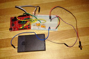
    Soldering went alright, though without a stencil it did take a little while. Out of the three boards I assembled, one worked perfectly, one nearly worked with the exclusion of one of the LEDs, and one stubbornly refused to do anything at all. Not bad for a rushed soldering session, and I only needed one to work fully anyway. Some hastily thrown together Arduino code later, and we have light!

    Not too bad, not too bad. Seeing all the fun colors was quite nice, though it was a pretty uneven spread of intensities. I wrote a little helper to normalize the intensities and that resulted in a pretty good looking SAO, I felt. It turned out that the OHS badge designer chose to not connect the I2C lines (sad) but did connect the GPIO pins (yay) which meant a little I2C bitbanging and the SAO was OHS-compatible. 

    I had intended to write some effects to give a little motion and intregue, but ran out of time for OHS. Hopefully I can do something fancier for next time, though generally I was very pleased that it worked out given the super short timeline I was working with. 

  • Initial Design

    Reid Sox-Harris10/13/2024 at 18:04 0 comments

    I did a writeup for the motivation for this design over here, but the end result is that I wanted to put as many wavelengths of LED as I could onto a CIE 1931-shaped badge. 

    The first challenge was finding all the LEDs needed for this. Because this was in a SAO form factor, I was limited to using small 0603 or 0805 LEDs instead of the big, powerful Chip on Board LEDs. This means all the LEDs will have to come from the "Indicator LED" section on Digikey where there is generally less selection of color -- who cares if your indicator light is a slightly deeper shade of red than a standard 615nm red? A bit of a challenge, but I managed to find 12 unique colors plus four shades of white for a total of 16 LEDs:

    Color NameWavelength (nm)v1 P/N
    UV456150224BS73100
    Deep Blue465APT2012QBC/D
    Blue470QBLP631-IB
    Teal496SMLD12E3N1WT86
    Emerald505SMLD12E2N1WT86
    Green525QBLP631-IG
    Yellow-Greener560SML-M13PTT86
    Yellow-Green570QBLP631-AG
    Yellow590QBLP631-Y
    Amber605QBLP631-O
    Red625QBLP631-R
    Deep Red640QBLP631-S3
    Soft White3000KQBLP675-IW-WW
    Cool White4000KQBLP675-IW-NW
    Bright White6000KQBLP675-IW-CW
    Daylight11000KQBLP661-IW5-CW

    I think my favorite are the Teal and Emerald LEDs from Rohm: they're marketed as being indicator lights for color universal design to make indicators apparent for colorblind folks. Pretty neat!

    Of course, with all these LEDs comes a requirement to control them. Since the goal of the design is to show off how color mixing works, intensity control of each individual LED is required. Ideally the badge will be able to control the SAO, so I opted to use the SAO-spec standard I2C interface connected to a driver chip of some sort. I looked through a bunch of driver ICs and eventually settled on the LP5018RSMR constant current LED driver. This chip has a few advantages: first, controllable over I2C. It's designed for controlling RGB LEDs, but allows you to control each individual channel just fine which is what I'll be using. Additionally, it uses constant current control, which means I don't need a separate current-limiting resistor per LED -- reducing the amount of soldering and making layout easier. Finally, it's not a matrix-style controller, so all I need to do is provide power to the anode and route the cathode to the IC, again making layout easier. 

    I wanted the badge to not only work well but also look nice, which led to the decision to only do bottom-layer routing. I wanted the top layer to only have LEDs and silkscreen for a cleaner look, which made this IC even more useful as it greatly simplified single-layer routing. 

    All that's left is a bit of power protection to prevent reverse voltage (using a PMOS reverse polarity circuit) and prevent overcurrent from damaging the host badge (using the AP22653AW6-7 current limiting power switch) and we're good to go!

    Because I love being difficult, I wanted to do any-angle routing + curves for the entire board to embrace the non-rectangular nature of the CIE1931 horseshoe. Lovely idea in concept, complete pain in practice. Altium is already iffy with any-angle routing, and the moment you try to throw curves in there it gets rather nasty. Thankfully there were not too many traces to have to coax into the right place, and the end result is appropriately swirly. 

View all 3 project logs

Enjoy this project?

Share

Discussions

Similar Projects

Does this project spark your interest?

Become a member to follow this project and never miss any updates