Stephen Holdaway
-
PCB Layout, Engineering challenges
02/22/2017 at 00:17 • 1 commentEarlier this week...
![]()
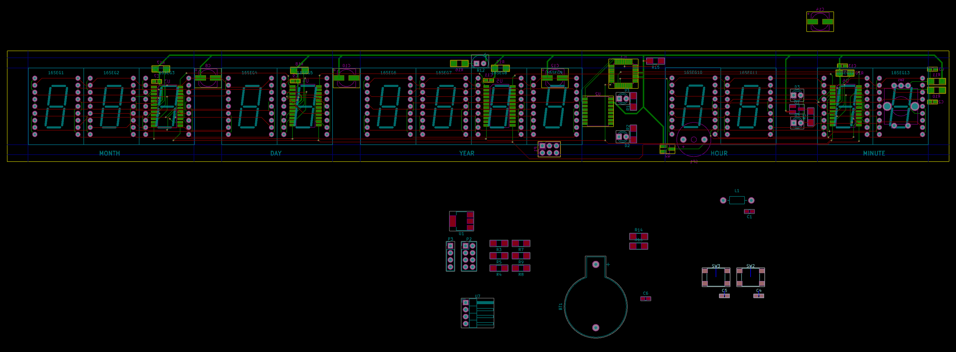
It became clear pretty quickly that 340 x 40mm isn't a whole lot of space for PCB layout when there are 234 through-holes spread evenly across your board.
Since KiCAD requires some manual prodding to create multiple boards from a single schematic, I had a play with putting all the components on one double-sided board before breaking the project into multiple boards. A bit of fiddling confirmed that both the control and display boards are too complex to route singled sided (without some trickery and a lot of time), so the display board will be a single PCB that I'll have manufactered by a fab house instead of doing it myself.
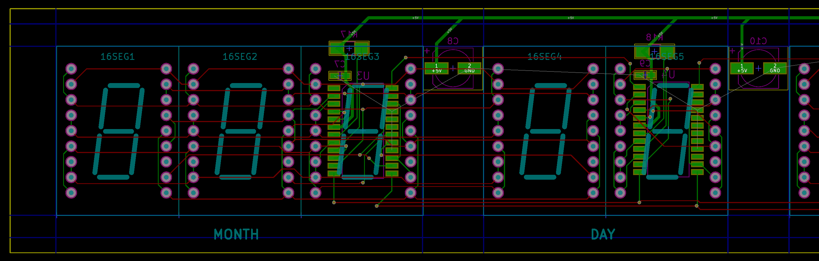
The display drivers just fit inside the footprint of a single segment, which is great because there's not really any other place to put them:
![]()
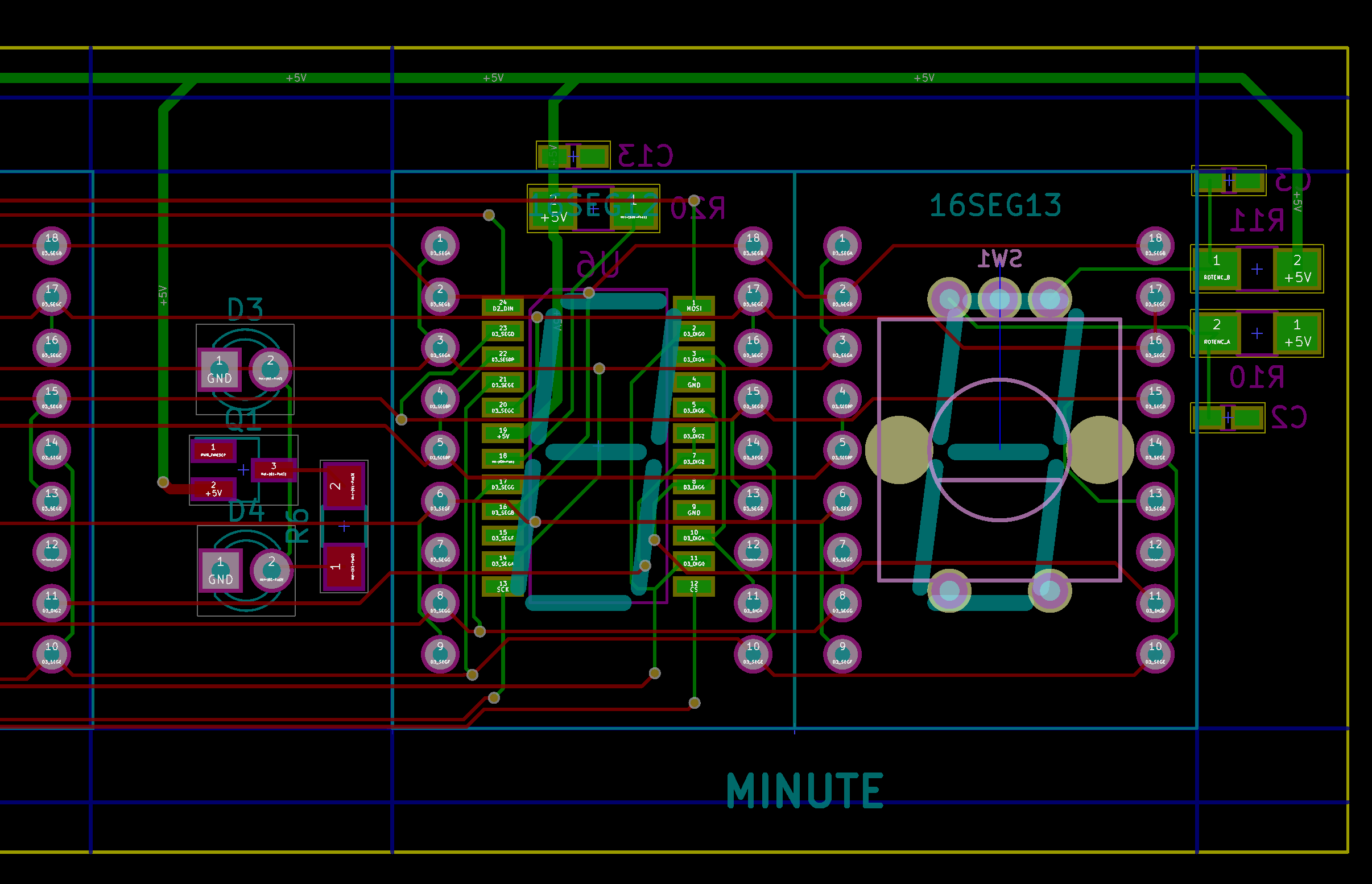
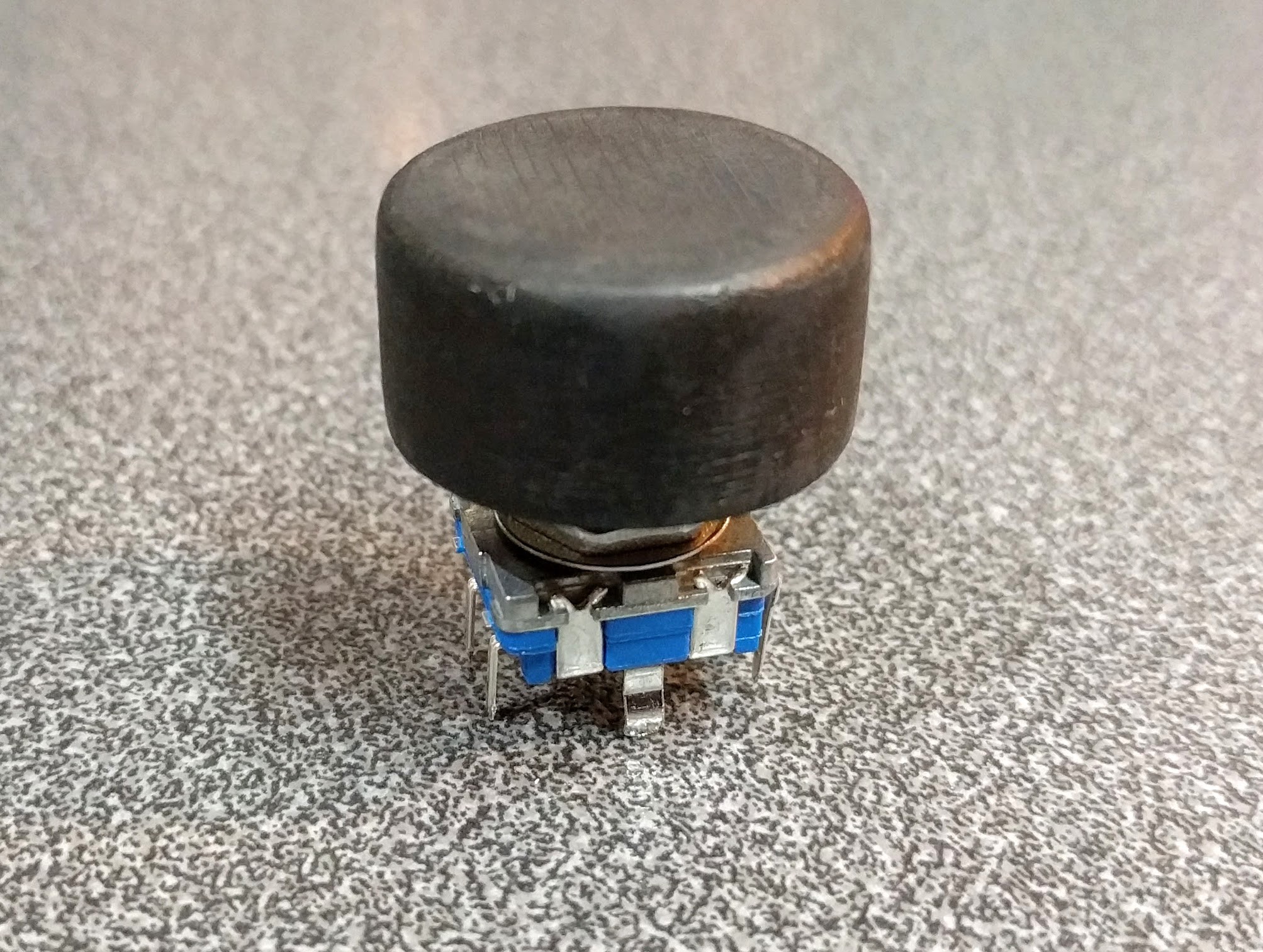
Another challenging part to place was the rotary encoder - the primary control for this device. In order to not have the knob stick out the back too far, this needs to be mounted on the display PCB, however it also needs to line up with one of the access ports in the back of the enclosure. With these constraints, there was really only one place to put it, and it's a tight squeeze:
![]()
The 16 segment displays I'm using have a 1mm air gap under them when mounted, which should be just enough to clear the pins from the rotary encoder once they're trimmed. Not ideal mounting it this way since the overlapping display segment would need to be desoldered if the rotary encoder needed to be replaced at some point.
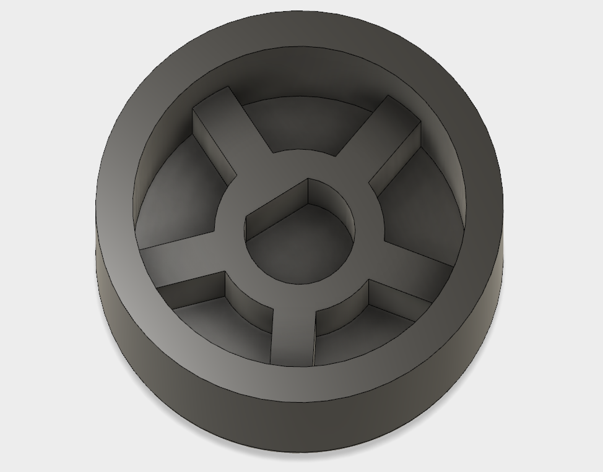
As part of figuring out this positioning, I also went and 3D printed a knob for the rotary encoder:
![]()
![]()
Flicking between enclosure design, positioning controls, PCB layout, and figuring out how to use limited available space really makes me appreciate how much combined engineering effort goes into even the most mundane consumer electronic device. That said, I've drawn myself into a corner somewhat by designing as I go, rather than planning the entire product before starting anything. Makes for interesting challenges in any case.
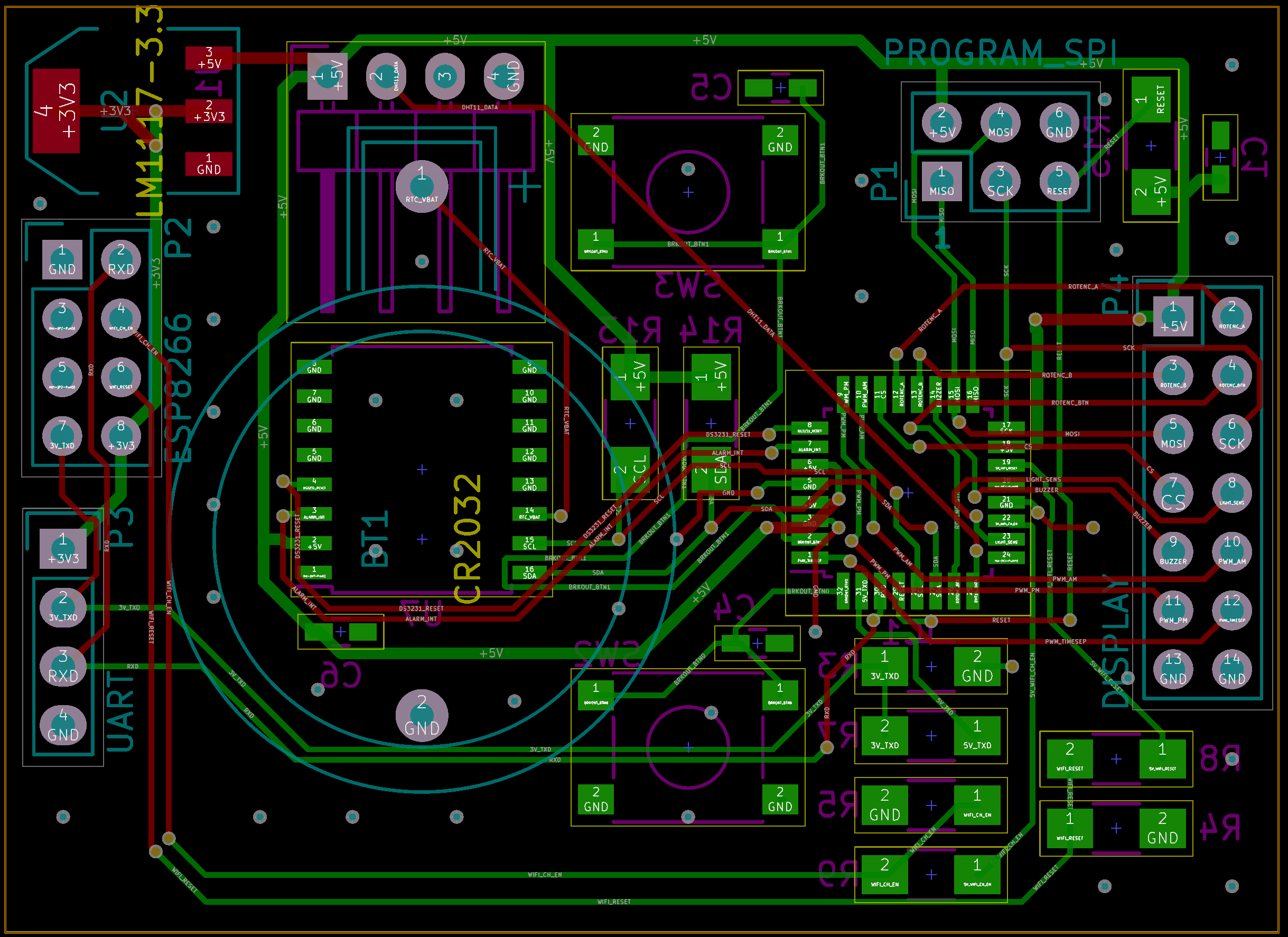
Present day - PCB layout done
To keep the control board small, the piezo buzzer and light sensor have stayed on the display board along with the rotary encoder. Everything else is on a 40 x 55mm board that connects via a 14 pin header:
![]()
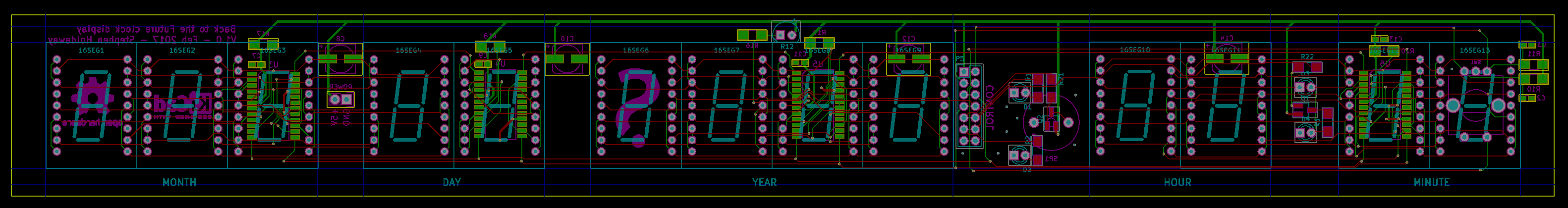
The display board hasn't changed much from earlier:
![]()
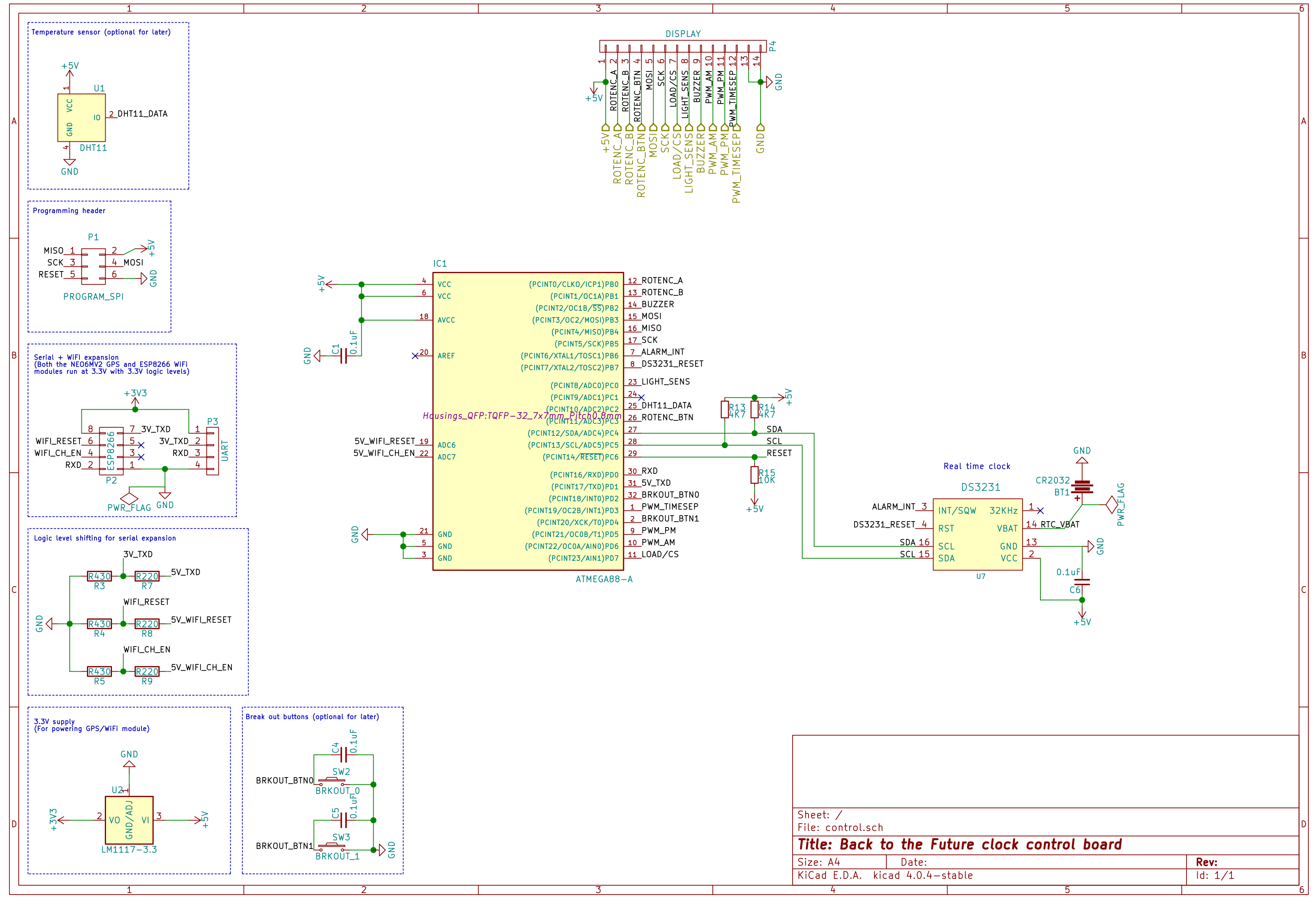
Schematics have been tweaked, but mostly just moving things around:
![]()
![]()
Testing display footprint
I've also done a quick test to confirm that the display segment footprint based on the datasheet has enough tolerence for the segments to fit together. Works a treat:
Next step is to get these boards manufactured. A little bit scary as this is only the third PCB I've designed... hopefully no major mistakes.![]()
-
Back covers printed
02/18/2017 at 09:26 • 0 comments![]()
A thinner revised version of the rear access port has printed significantly faster the original version and without much warping. Due to printing in a different plastic however, this print ended up too small to friction fit onto the enclosure again.
Rather than adjust the model and print again, I made a few notches on the hidden inside lip by softening in places with a lighter and deforming with the handle of a teaspoon. This worked perfectly, so I printed a second and made the same modification. Hopefully this will be a little more durable than an unmodified print, since the plastic has fused across layers in the places that are stressed when snapping the cover on.
![]()
-
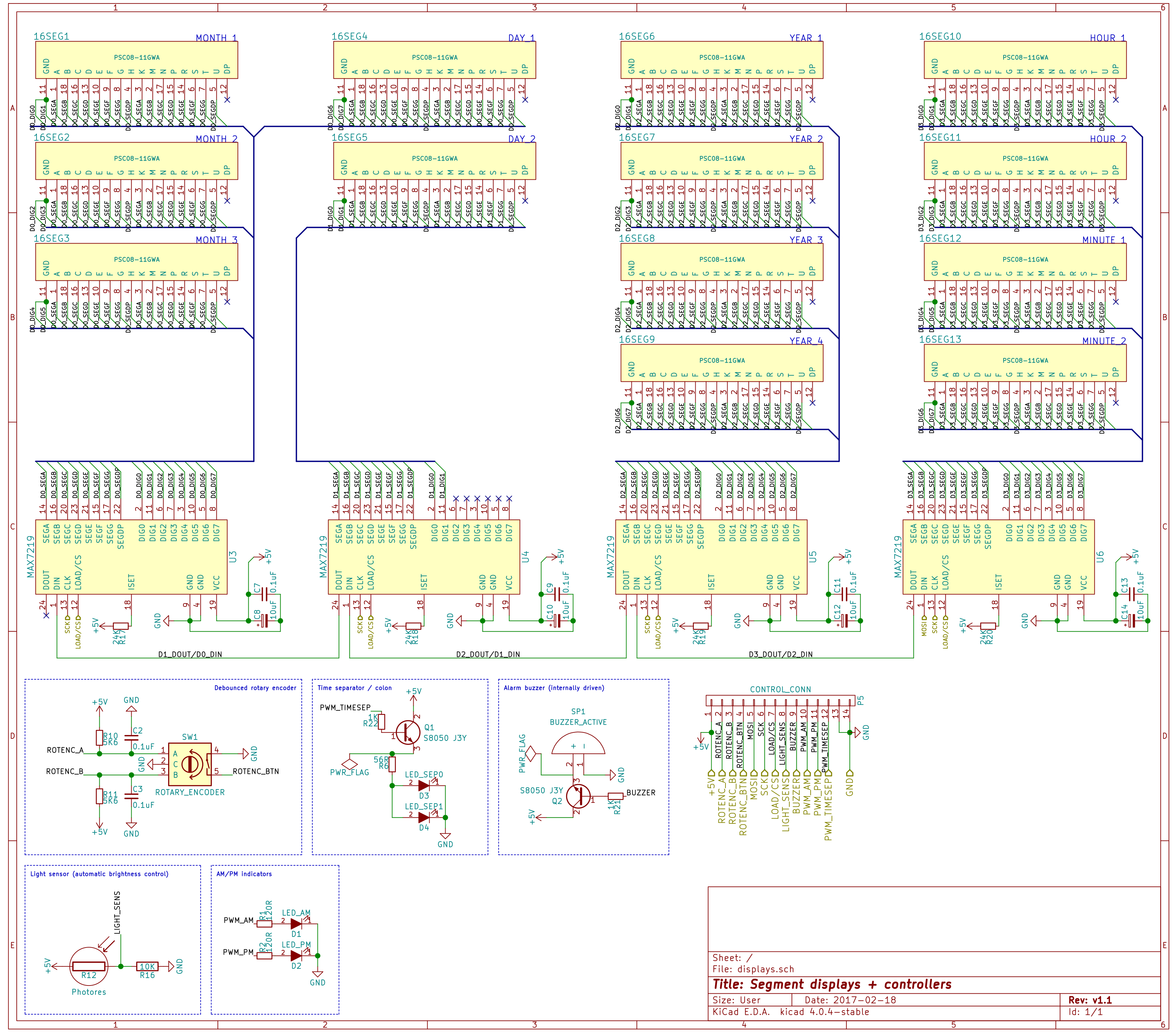
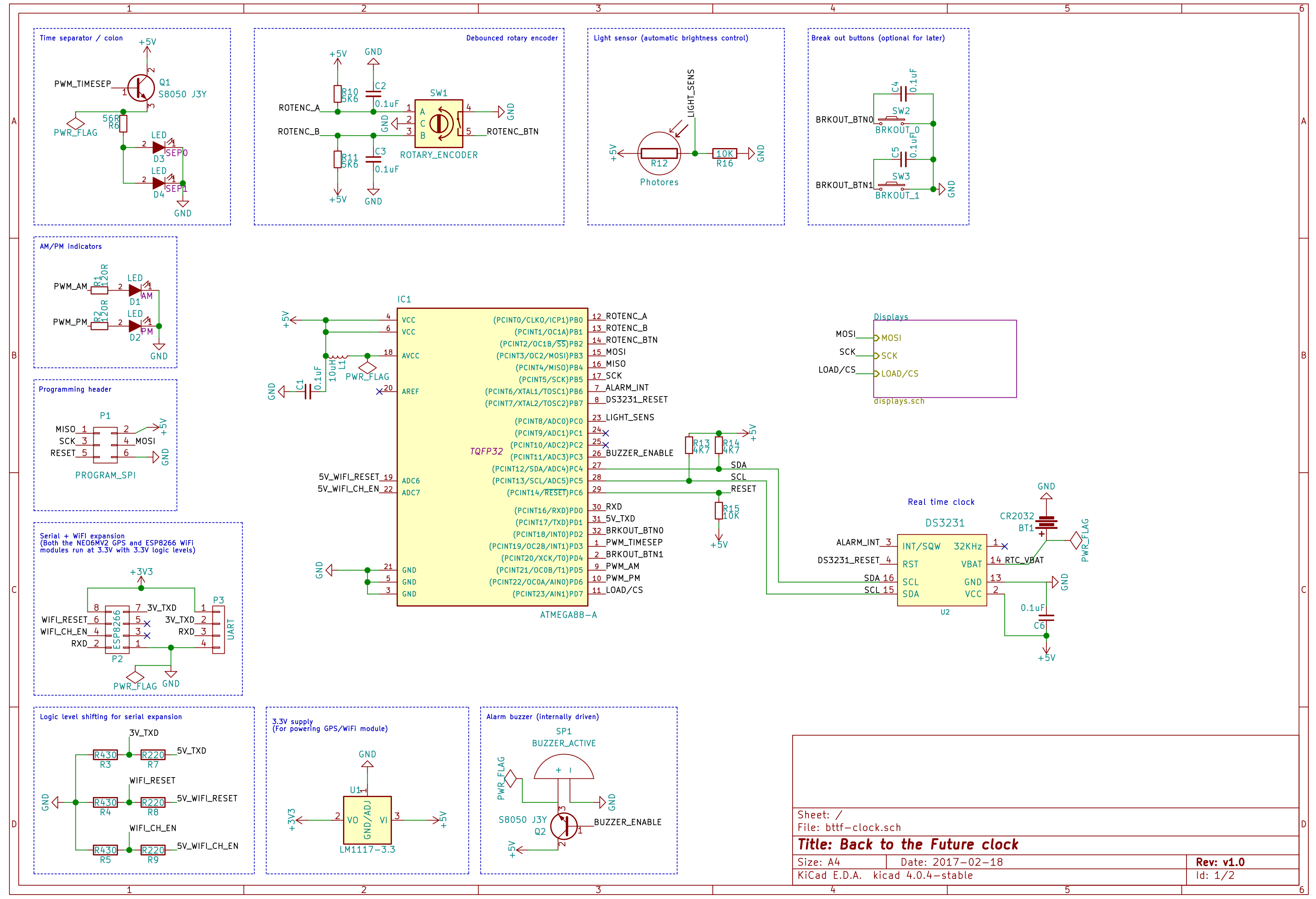
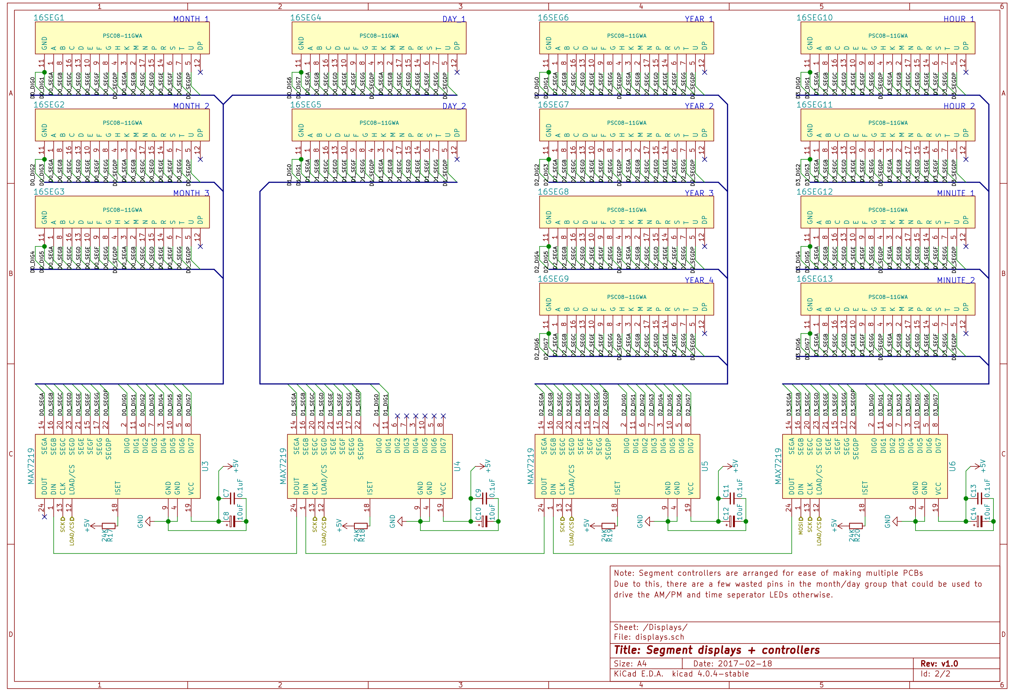
First draft schematic
02/18/2017 at 05:19 • 0 comments![]()
![]()
Schematics with KiCad! Previously I've used Eagle, but as this was originally going to be a single 300mm x 40mm board, Eagle wasn't going to work with its restrictive board size limits. I'm currently deciding whether to have a few smaller boards or one large one. Smaller boards are easier to mask and etch by hand, and errors are less costly, so if I can route these display boards single sided I'll just etch them myself.
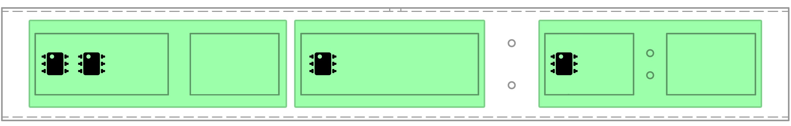
The plan for multiple display boards is this, where the IC icons represent which boards hold which driver chips:
![]()
By having driver chips only connected to segments on their own PCB, there's just five connections to make between each board (VCC, GND, DIN/DOUT, CLK, LOAD). The schematic is wired assuming this layout.
Design notes so far:
- This has to run at 5V as the MAX7219 chips don't support a lower voltage
- I'm using the internal 8MHz oscillator in the Atmel ATMEGA88 rather than an external one
- At one point the AM/PM and time separator LEDs were connected to spare outputs on last MAX7219. Since the multiple boards plan moves the spare outputs to the left side the enclosure however, I've opted to use three PWM outputs from the MCU rather than running wires the length of the enclosure.
-
Backdated updates (2 of 2) - plugging the holes
02/16/2017 at 10:03 • 0 commentsInitially I figured I might be able to cap the ends of the frame with metal by welding or bending some excess material. After talking to a few people familiar with metalworking however, I found neither of these were particularly good options: welding would destroy the zinc coating on the metal, and bending would be hard to do precisely with the tools we had available on an object this size and shape.
3D printing to the rescue.
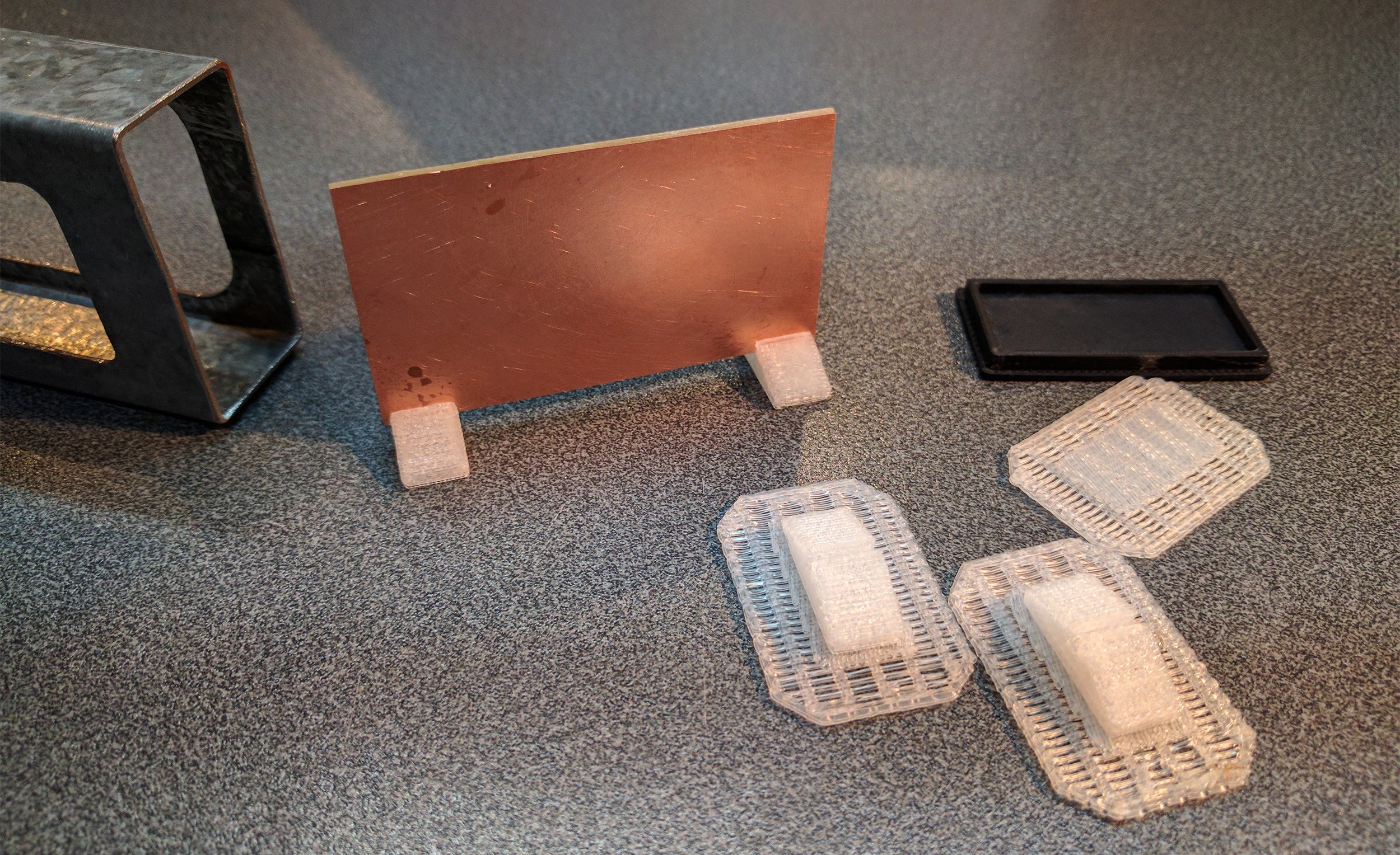
End caps
After a few corrections with digital callipers to match the real world object, it was quick to make up some parts that were exactly the right size:
![]()
![]()
The outside of these caps is sanded with 180, then 360 grit to give a smooth matte finish (I'm a big fan of sanding 3D printed parts for this effect). I might get some finer grit sandpaper to polish out the scratches later.
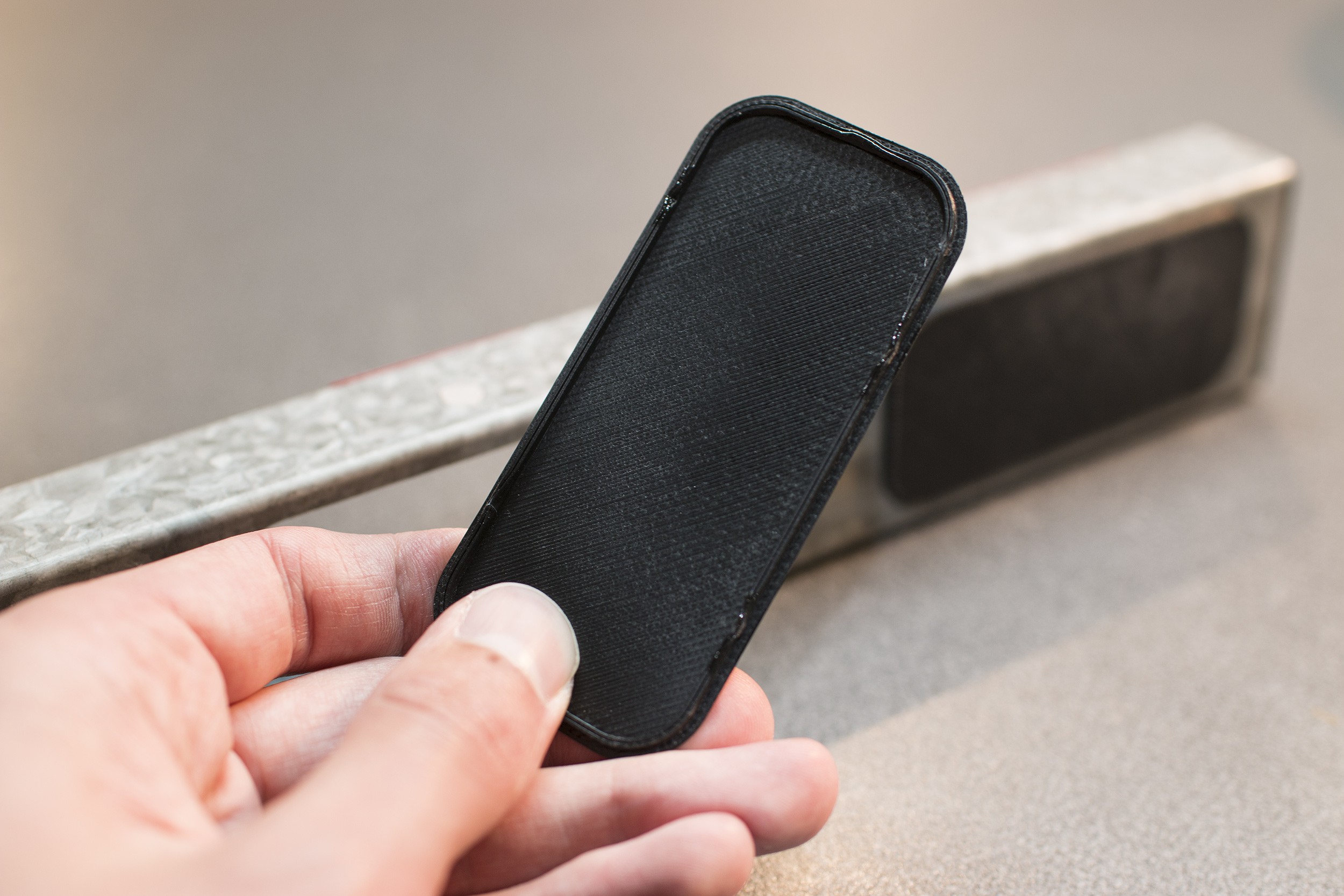
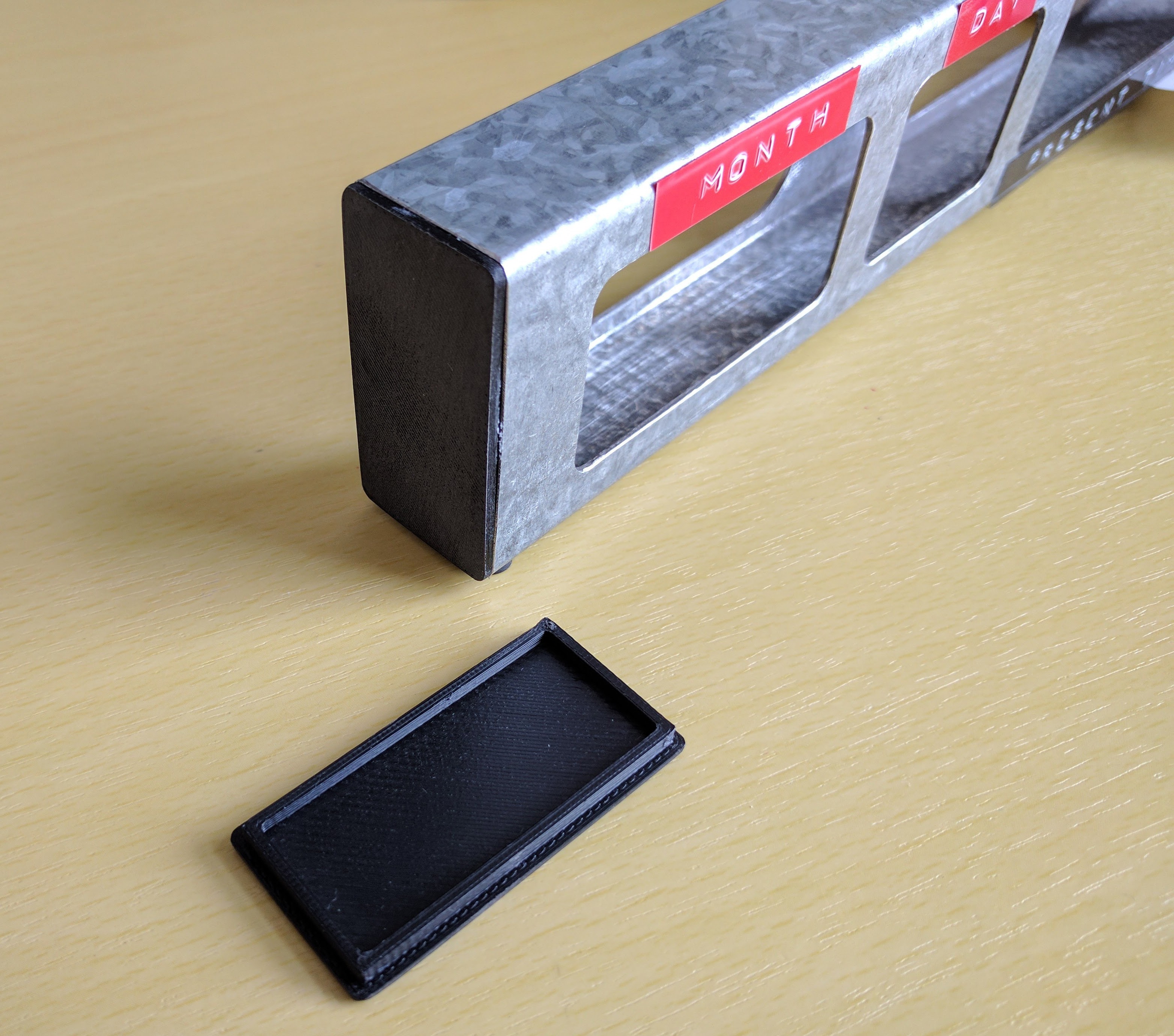
Rear access port covers
![]()
The first rear cover I printed was fractionally too small and didn't friction fit like it needs to. I haven't printed this again since revising. The revised version (image) is also slightly thinner, which should help reduce the slight warping I'm seeing from printing these in ABS.
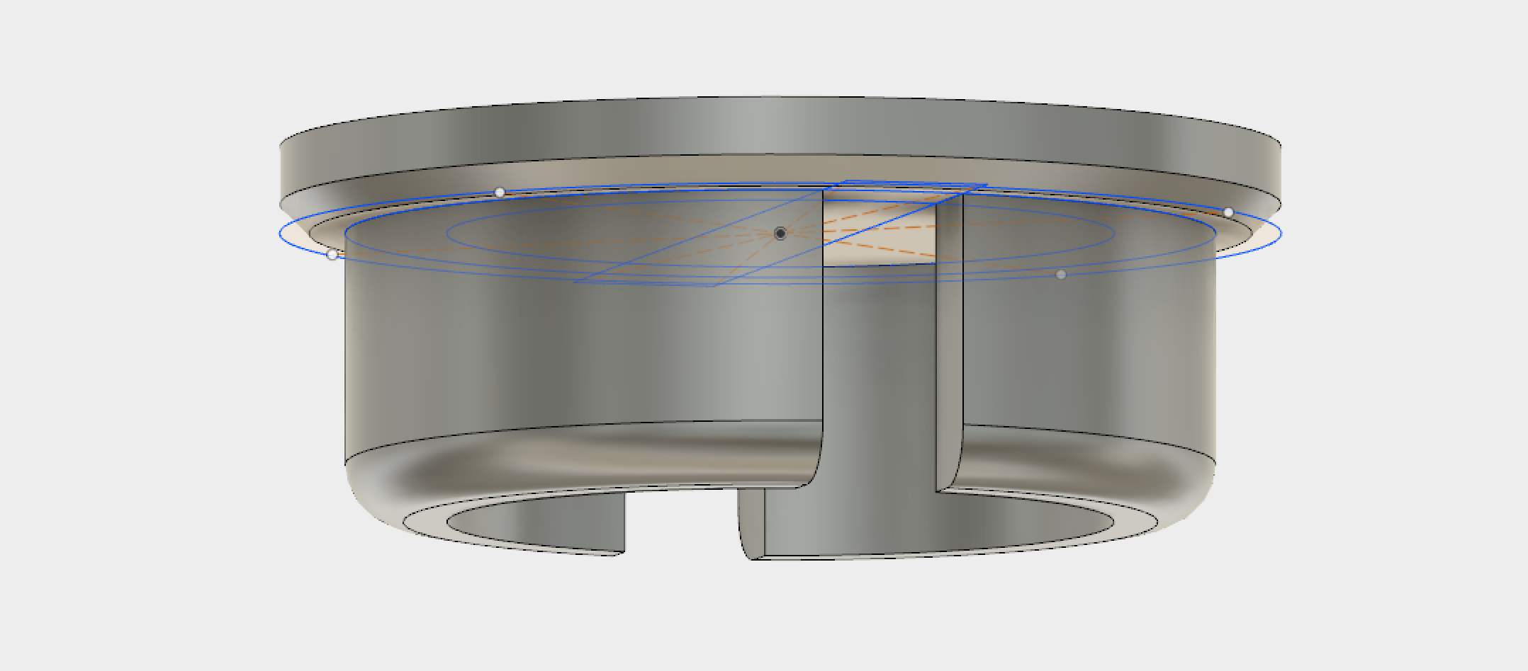
Light sensor cover
![]()
![]()
The light sensor hole is covered with a small, friction fit plug printed in semi-transparent plastic. The plastic I used doesn't have great light transmission, but this can be corrected for in software, or with a change of dividing resistor later.
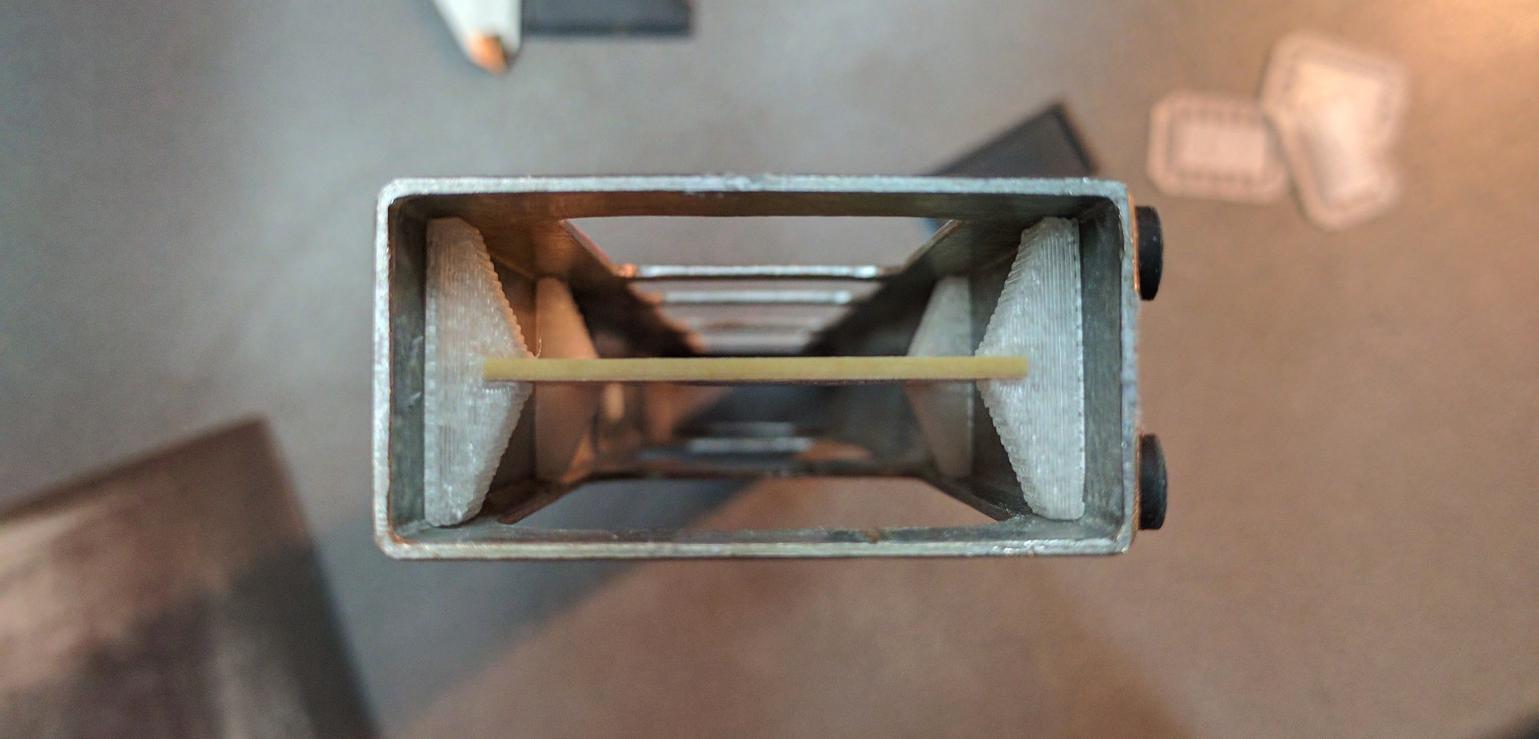
Test PCB mounts
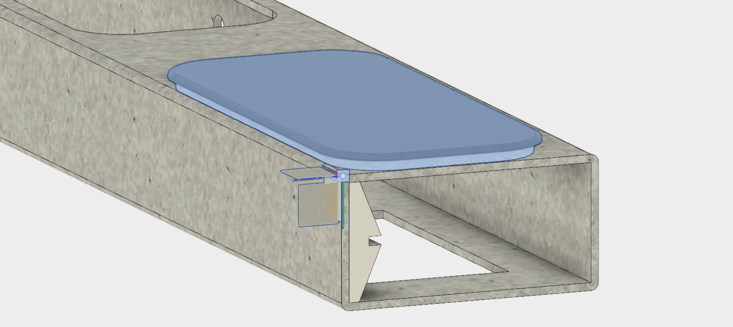
The PCB(s) for the segment displays will need to be held in place rigidly and be well aligned. I've done a quick test to confirm the mounting solution I had in mind would work. Test successful assuming a 40mm tall PCB. Friction fit seems to be enough:
![]()
![]()
Centering a 1.6mm thick board in the frame leaves 9mm clearance in the back, and 1.5mm in the front with the segments mounted. The front clearance should be just enough to fit coloured filters flush against the digits to increase contrast. The back clearance will hopefully be enough to fit a separate control board and any other components or power circuitry needed.
-
Backdated updates (1 of 2) - Building an enclosure
02/14/2017 at 11:39 • 5 commentsI've been meaning to upload this project to Hackaday since I started planning it a little before Christmas 2016. Now that I've left it sitting on a shelf for a month waiting for components to arrive (read: being lazy), here's an update on what you've missed so far.
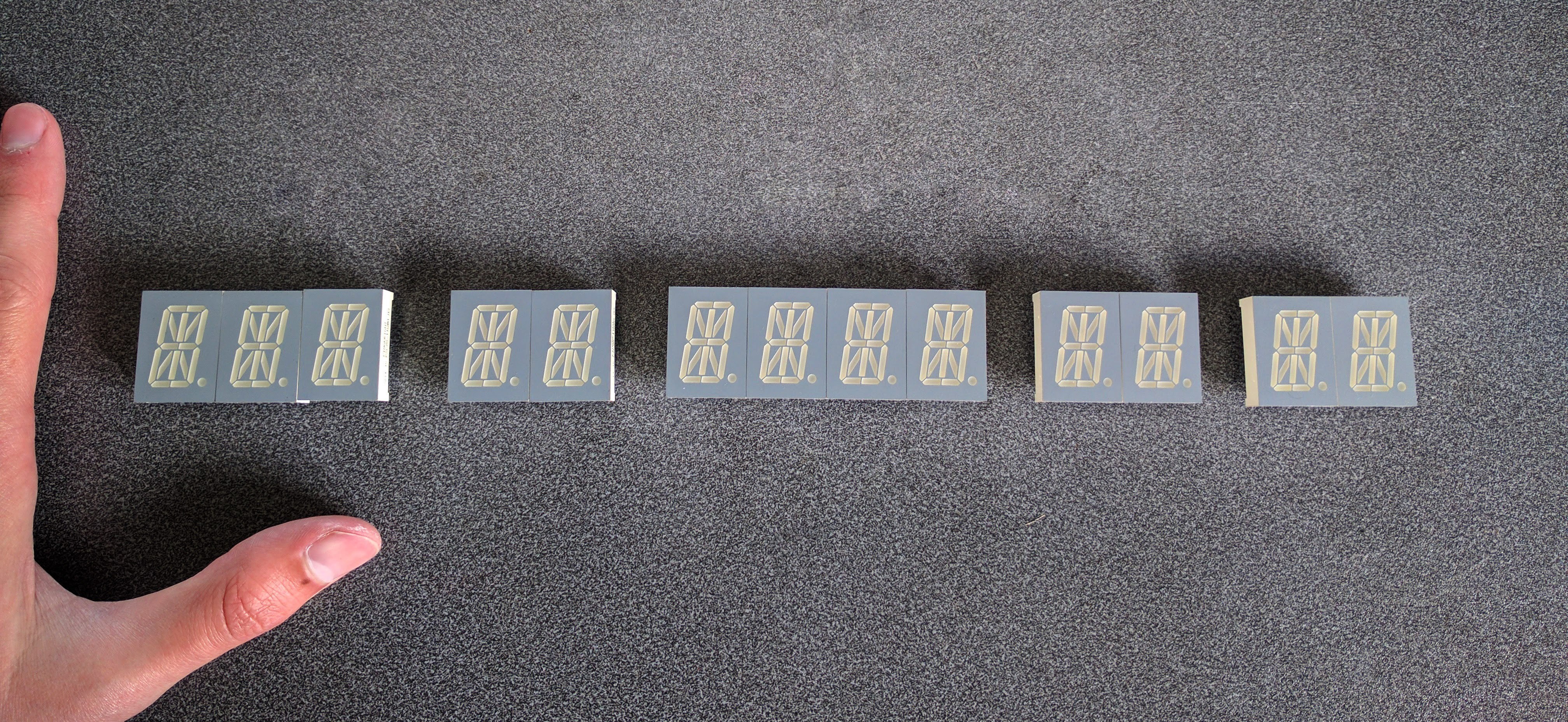
As soon as I had this idea, I went and ordered a bunch of components I knew I'd need. In retrospect it was possibly a poor decision to do this before designing anything, but we'll see how that turns out later on. The important bits I grabbed were:
- 13x 0.8" green 16 segment displays (replicating the green "present time" row in the time circuits). The movies use 3x 14 segment displays for the month and 10x 7 segment ones for the numbers, but I couldn't source green 14 segment displays, and it was far cheaper to buy only 16 segment displays instead of mixed 16 and 7 segment. A little different from the movie, but the spirit is there.
- A bunch of MAX7219 LED segment display driver chips. Four of these will need to be daisy-chained together to drive the 208 segments (excluding decimal points) in the displays.
Element 14 ships quickly to New Zealand, so after a few days we have this:
![]()
These were bigger than expected as I mistook 0.8" as a component height when it was really digit height (read the datasheet, silly). The chunkier size works quite nicely though, even if unplanned.
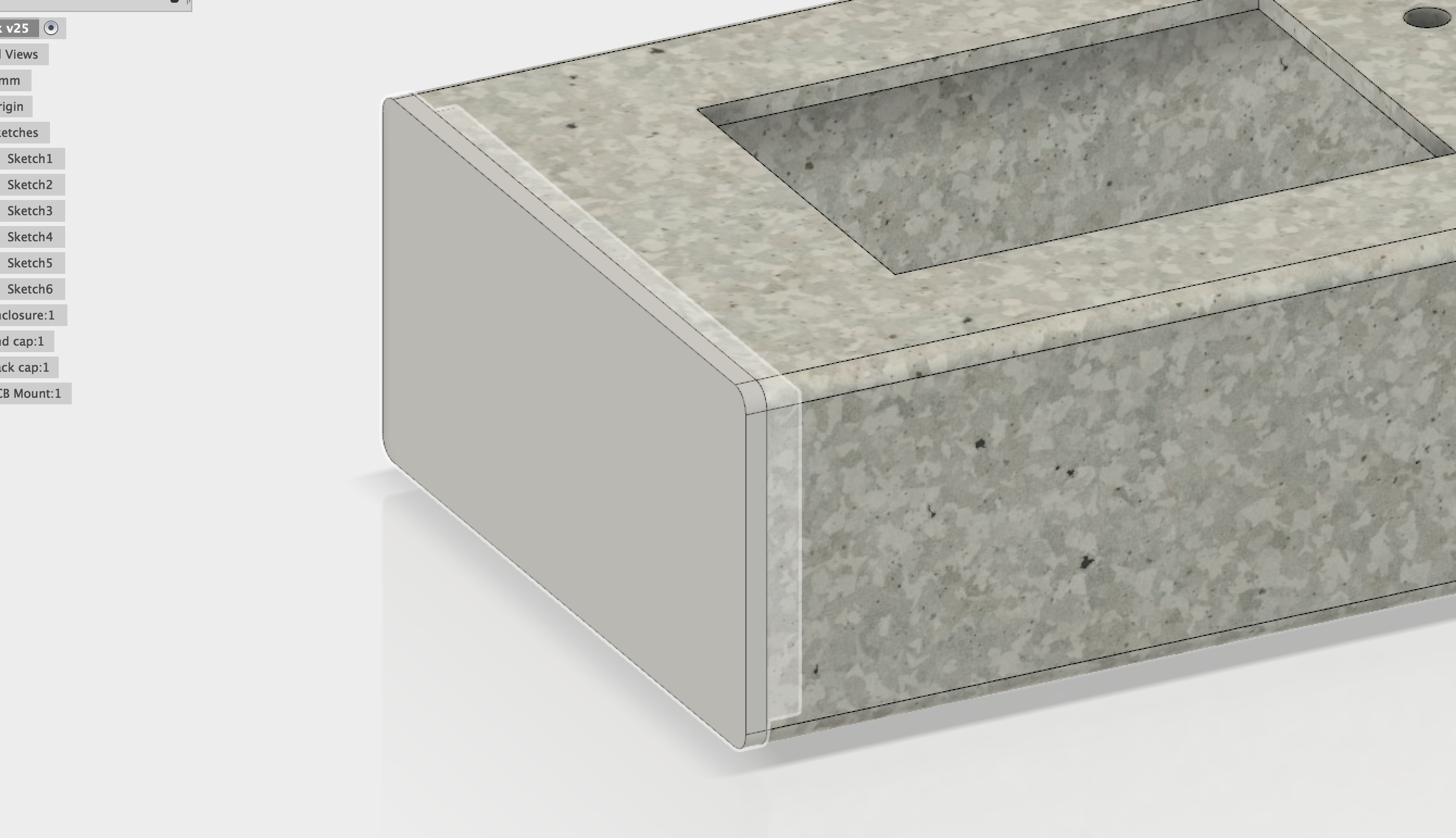
Building an enclosure
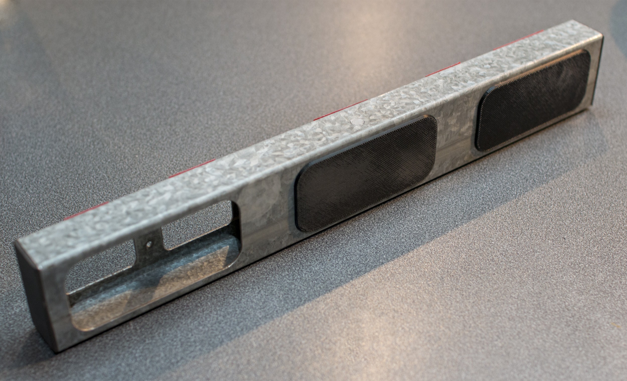
While browsing my parent's garage over Christmas, I found a piece of 1" x 2" galvanised rectangle hollow section (RHS) that matched the look of the galvanised sheet metal the film appears to use. You can buy this kind of stock at most building supply or hardware stores if you don't have any lying around. This one has 1.6mm walls.
![]()
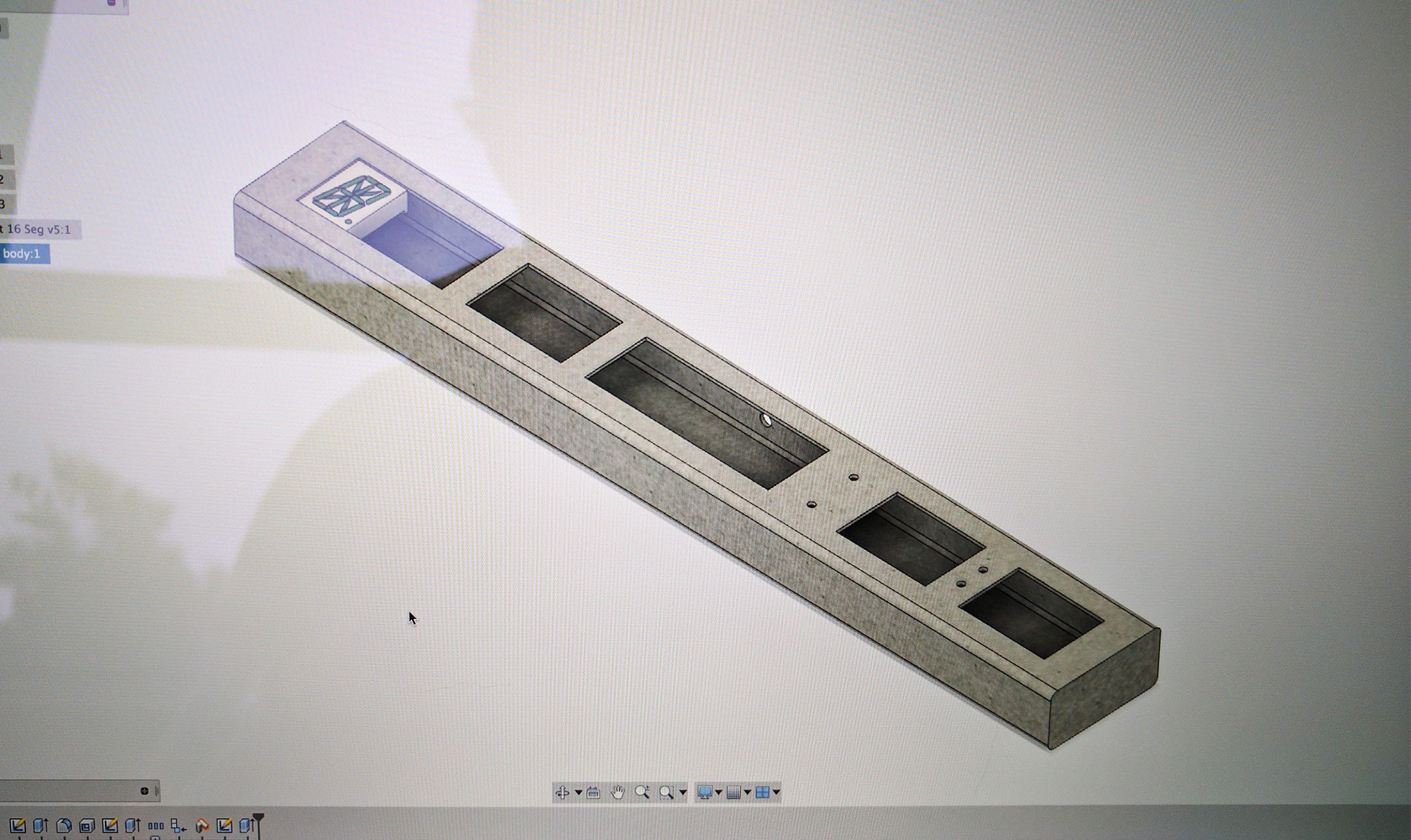
Excited by the possibilities of my newly acquired tube of metal, I took a ruler, Autodesk Fusion and roughed out how this could work. First rookie mistake: not enough tolerance around the digits, but more on this later. Apologies for the photo-based screenshot:
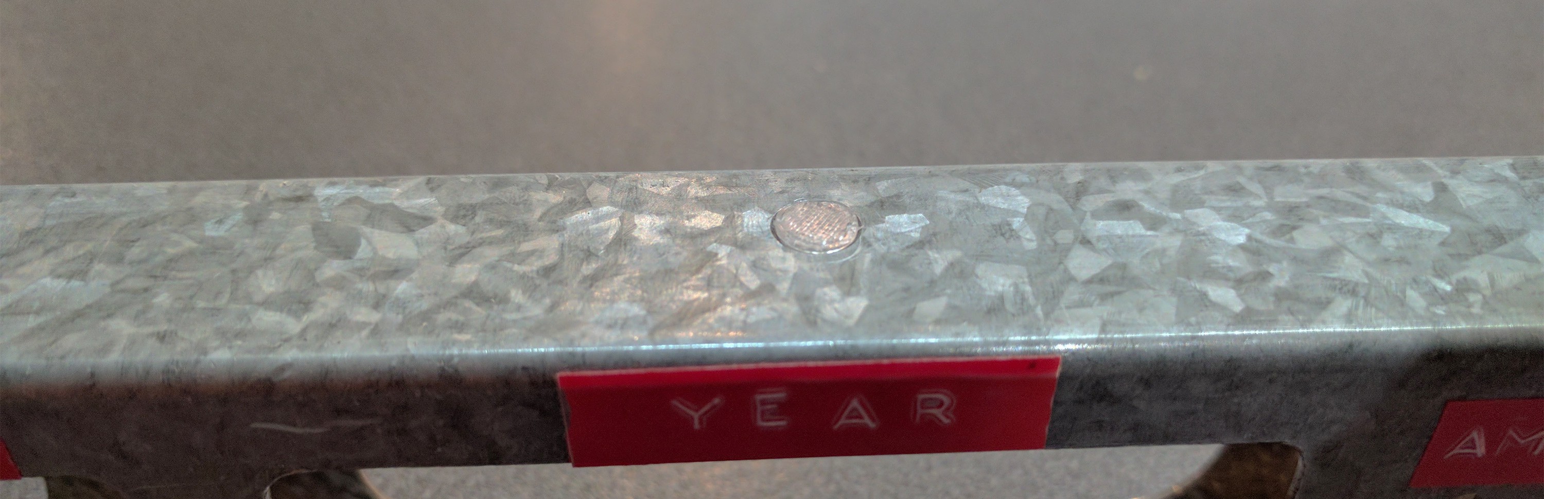
![]()
The AM/PM indicator is more spaced out than the film version as I have a ye olde' embossing label maker with relatively large tape. Another small deviation from the film version, but this is just a tribute. The hole in the top is for a light sensor (LDR) so the display brightness can be optimised for the ambient light level.
Milling the Metal
Having never really worked with metal, I figured I'd be at high risk of completely destroying my material if I tried to cut these precise holes myself. Fortunately, one of my uncles owns a Bridgeport mill, and he was happy to help.
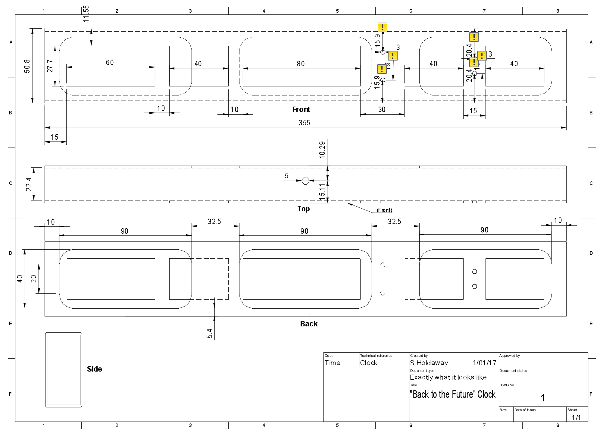
I hadn't decided how the PCB(s) would fit into the enclosure at this point, but figured a few good sized ports in the back would help with assembly. Converting the model to a drawing ended up with this:
![]()
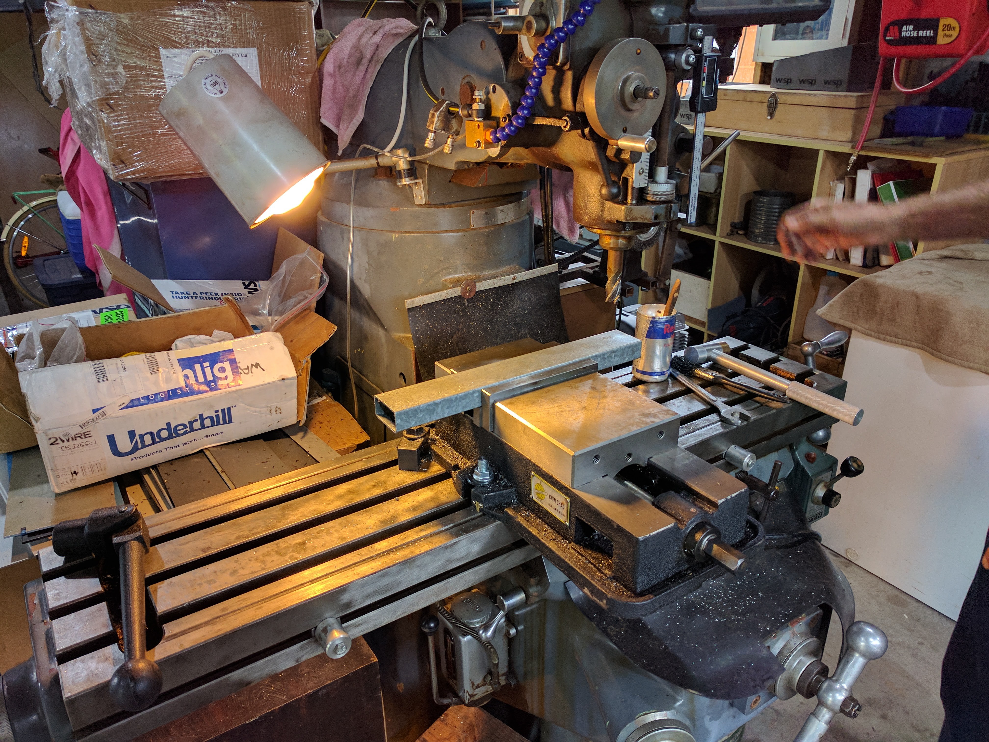
Then into the milling:
![Getting set up for milling]()
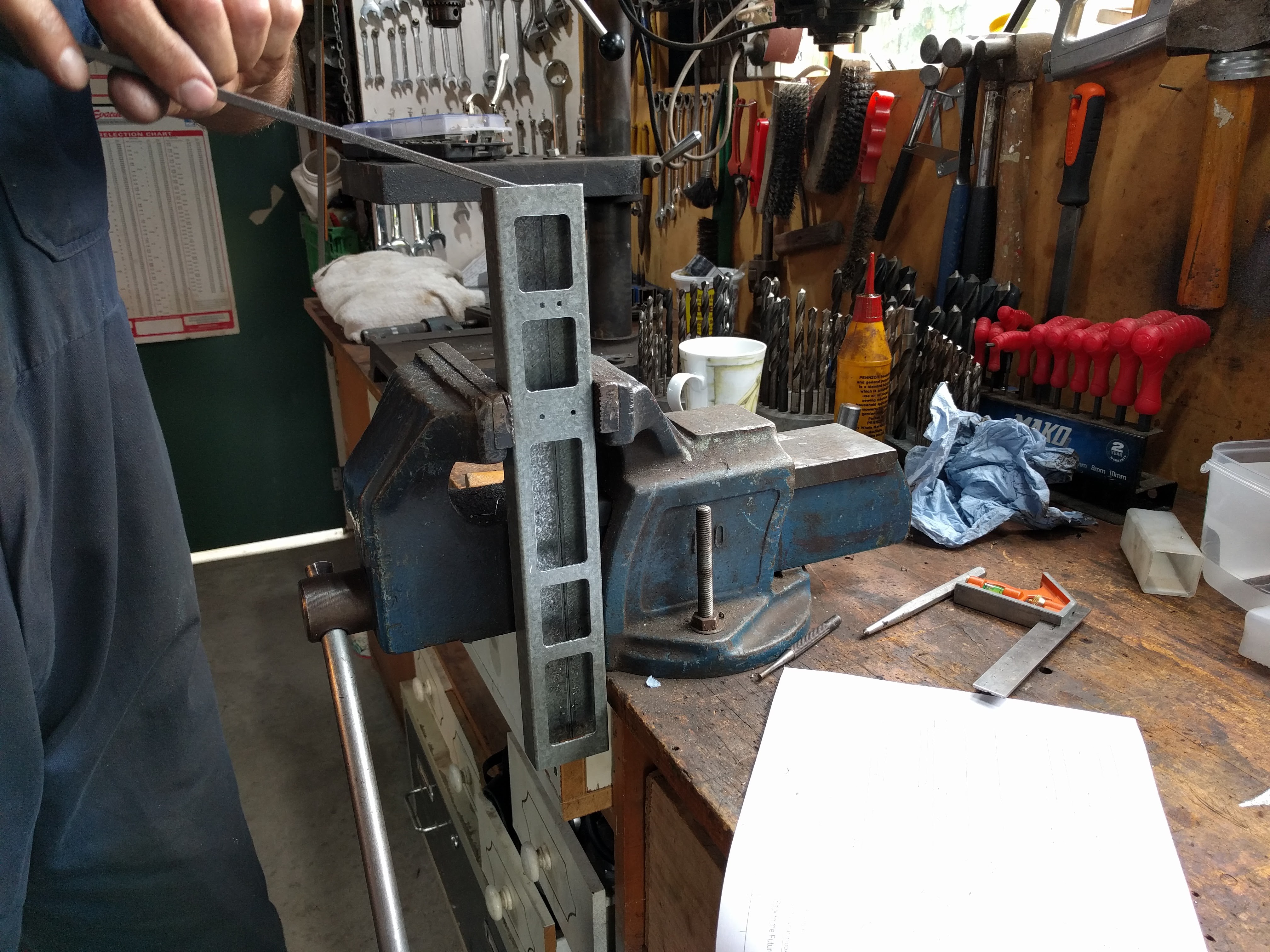
![After the front was milled. Some pretty nasty burrs on this.]()
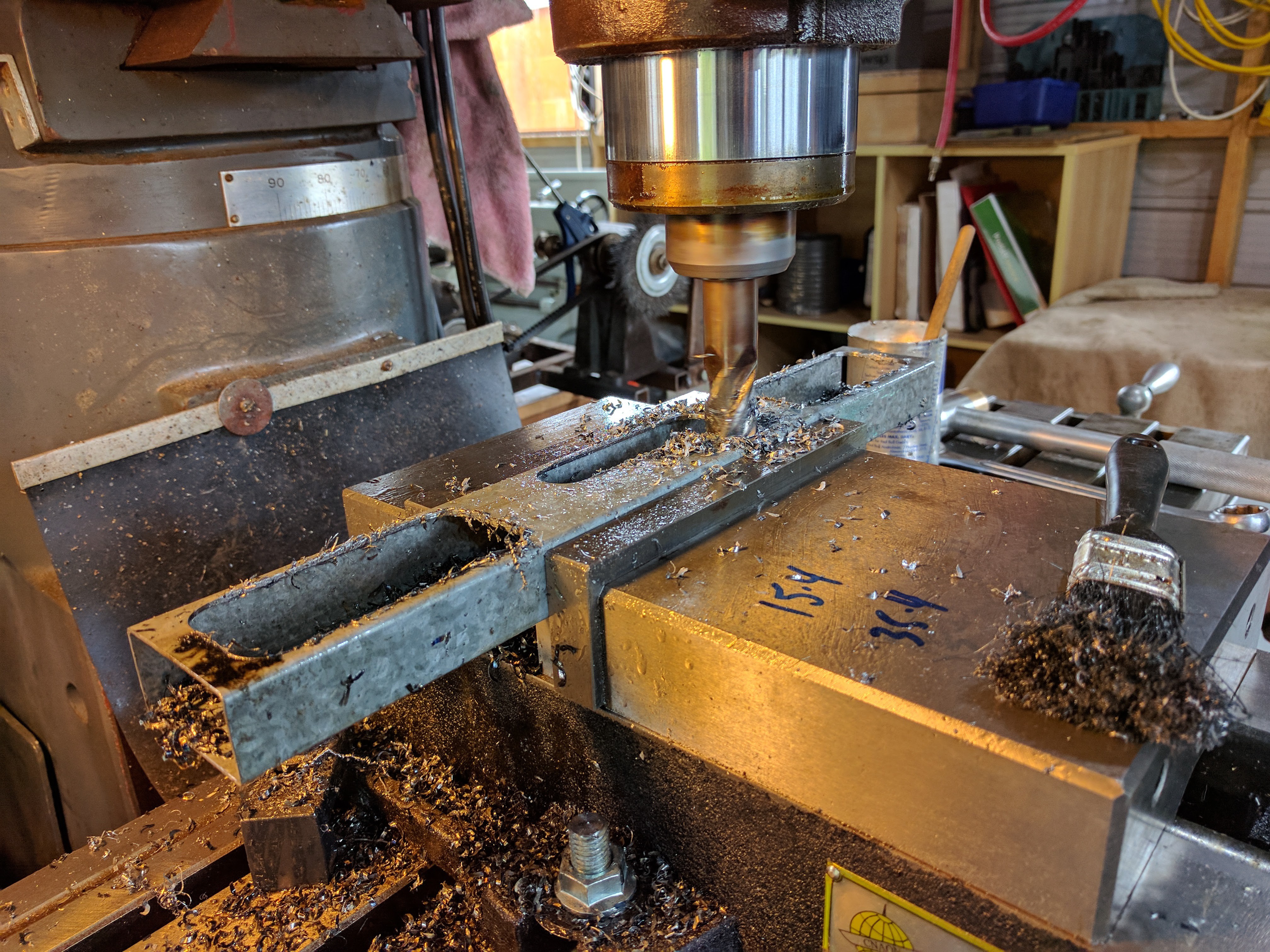
![Milling the access ports]()
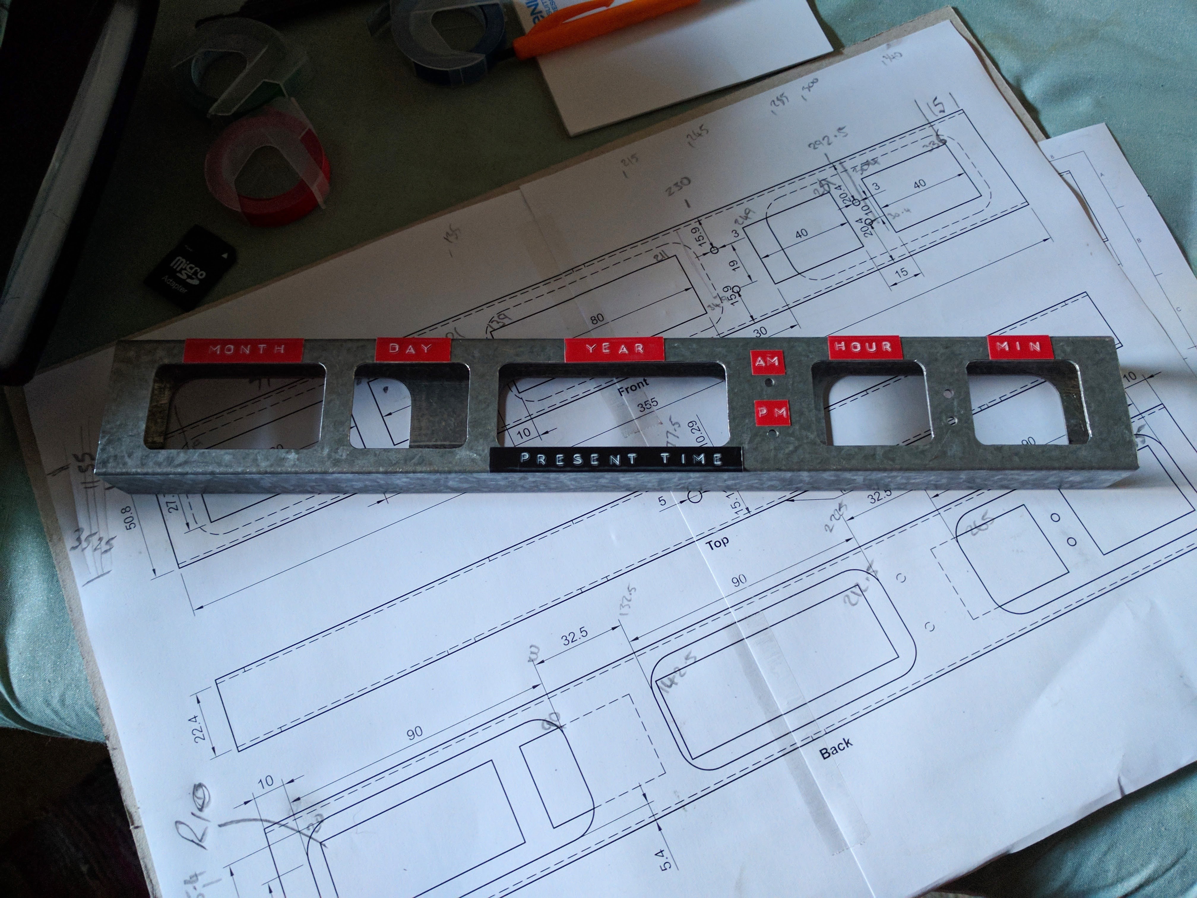
With a little more deburring and labels applied, the result was this:
![Milled and labeled, sitting on the 1:1 drawing with annotations]()
If you were looking closely, you might have noticed that the holes cut in the front are too big. You'd be right - in haste, we collectively made a few manual math errors and made the front cuts too tall. By the time we noticed, we'd milled too much to correct the error, so we just went with it. The displays will be covered by a transparent acrylic filter, so there's no problem with the larger holes other than having less space for the labels.
So that's the frame of the enclosure done - early January. There's one more backdated update about 3D printing end caps for the frame, then you'll be up to speed and we can get to the electronics!
![]()
![]()
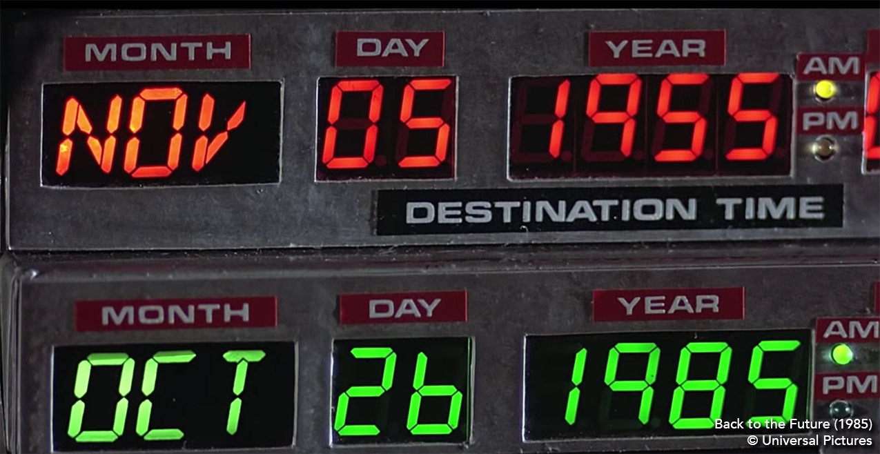
Time Circuits Timepiece
A practical-size, Back to the Future themed digital clock mimicking the "Present Time" portion of the DeLorean's time circuit displays.