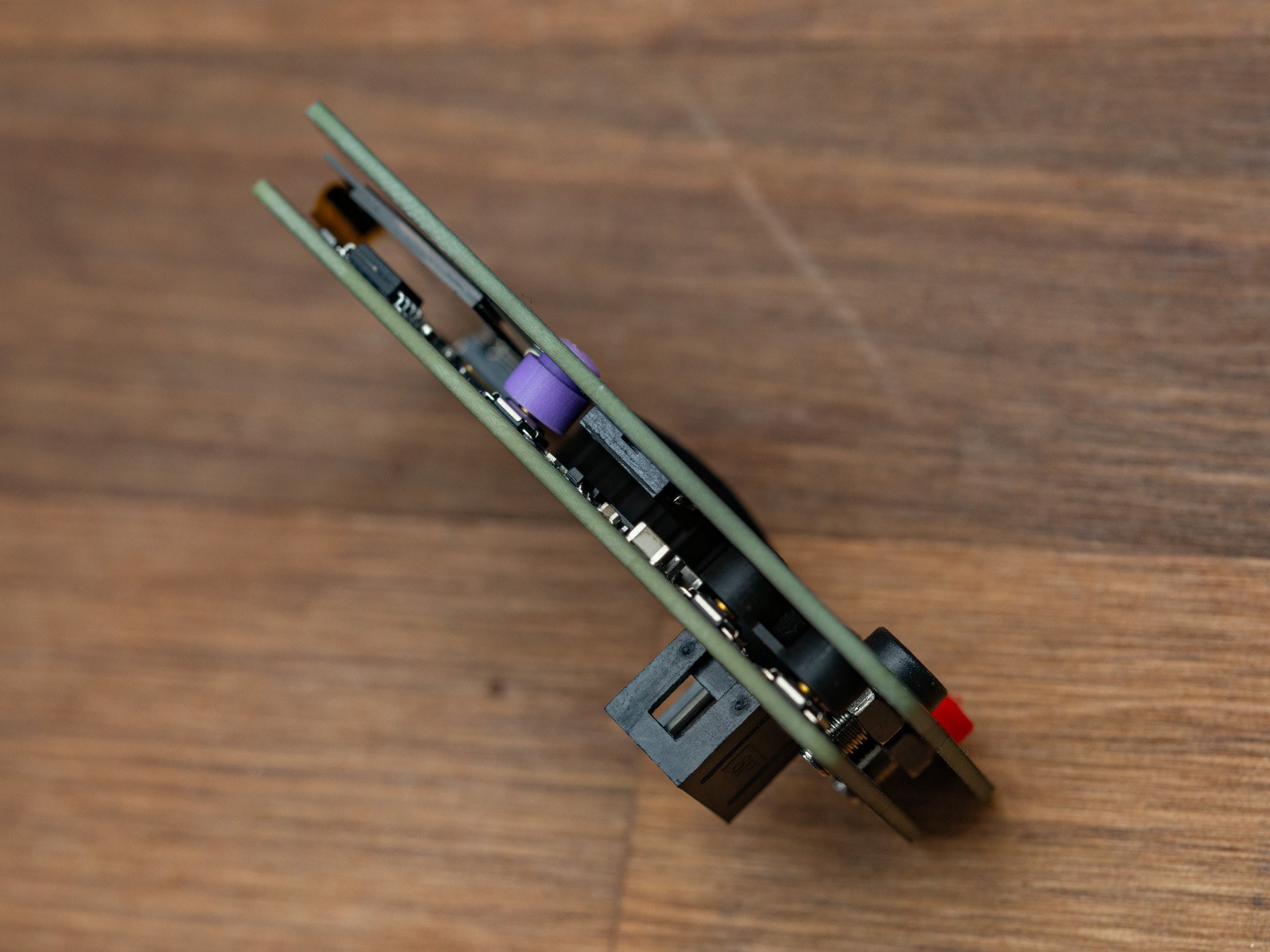
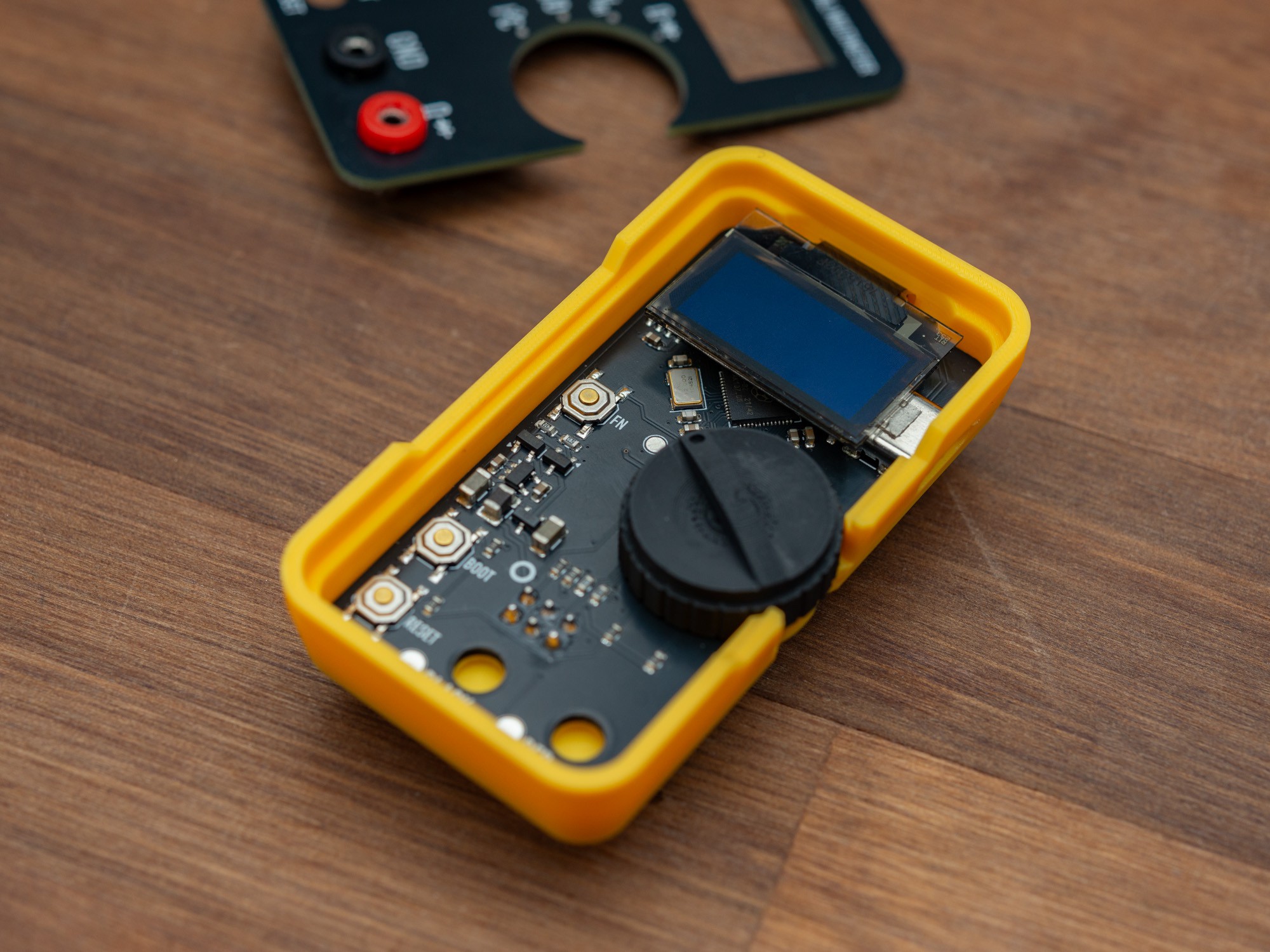
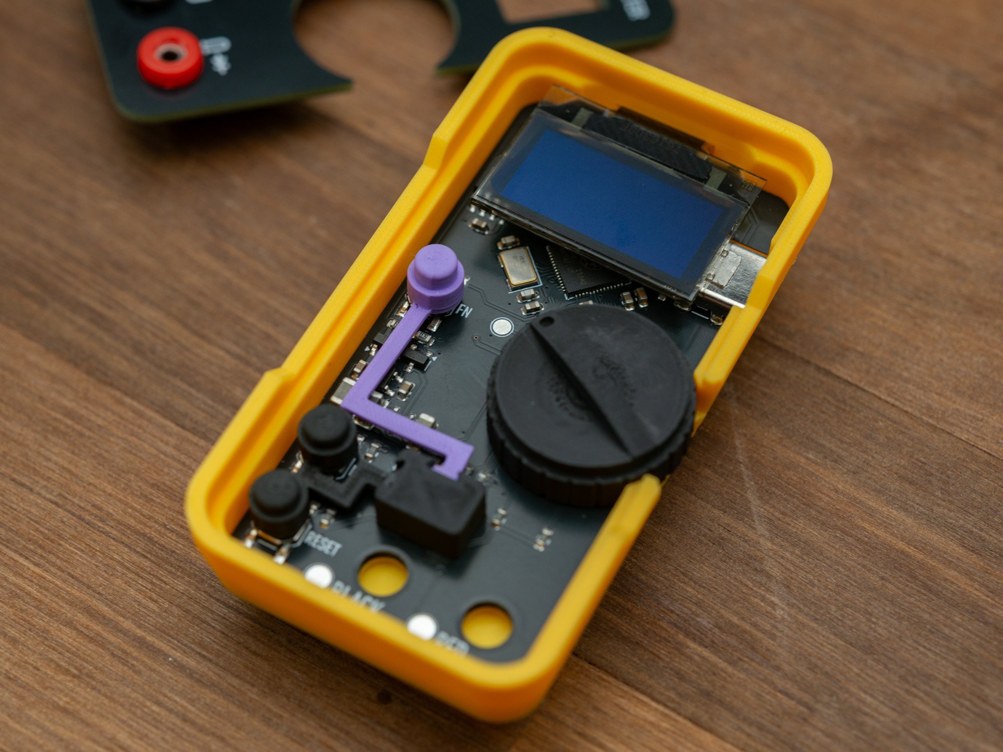
The electronics is sandwiched between the base PCB and the front plate. In between are all the components, screen and the button caps and the main mode selection knob. Only the SAO connector sits on the back.

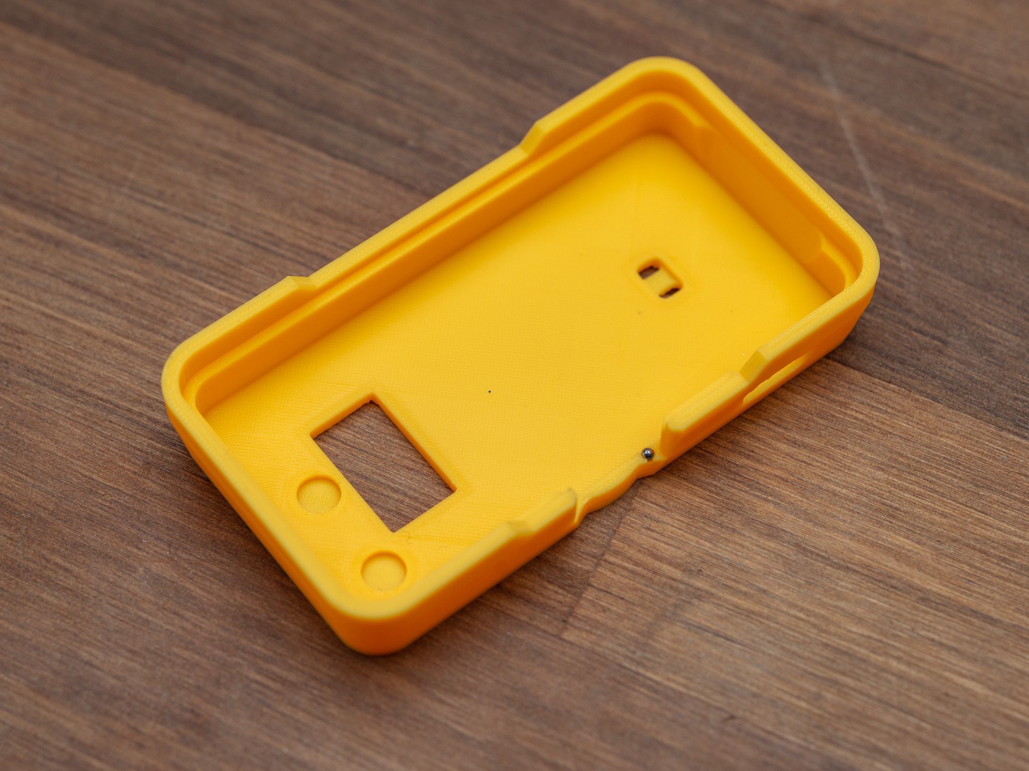
The case has a cutout for the SAO connector, small indents for the two 2mm banana sockets, and two small holes, to add a SAO leash, as an extra protection agains loosing a SAO that falls off a badge.
To have the screen sit correctly, the top of the case has been extended a little, to accommodate the flex pcb that connects it to the base board.
The distance between the boards is just enough to have the screen sit on top of the USB-C connector, about 4.9mm.

As the rotary encoder does not have stops but rotates smoothly, firm position locks are done by adding a small (Ø1.5mm) steel ball inside the case side, and adding indents for every 30° on the bottom of the knob. When the knob is squished between the two PCBs, this makes for a pretty decent feel.

The knob has small ridges on the outside, for better grib when using a thumb or similar to rotate.

The button caps are held in place by thin printed extensions, that connect to the spacer, that sits directly above the SAO connector, preventing the bottom PCB from moving in the case, especially when inserted into a badge.

 Thomas Flummer
Discussions
Become a Hackaday.io Member
Create an account to leave a comment. Already have an account? Log In.