Close
0%
0%

SAO Digital Multimeter

A small digital multimeter specifically for measuring SAO related stuff

Similar projects worth following
This is a digital multimeter, with an SAO connector on the back, mode selection knob and test lead connections on the front.

Features (implemented):

- Measure supply input voltage (from the badge)
- GPIO info (read, digital + analog)
- LED/Diode test
- Continuity test
- Resistance measurement

Features (planned):

- I2C Tester
- GPIO info (write, digital/PWM)

Designed mainly as an assistive device during badge development, but also as an exploration of multifaceted engineering, combining electronics and mechanical design to have a relatively compact end product, that also looks right.

Status

  • The electronics design is complete, though issues might surface, when diving deeper into the firmware part.
  • Mechanical modeling could use a little improvement for holding the face plate in place, but the layer lines from 3D printing does a pretty good job with the snug fit.
  • Firmware is lacking and the main focus at the moment.

Electronics

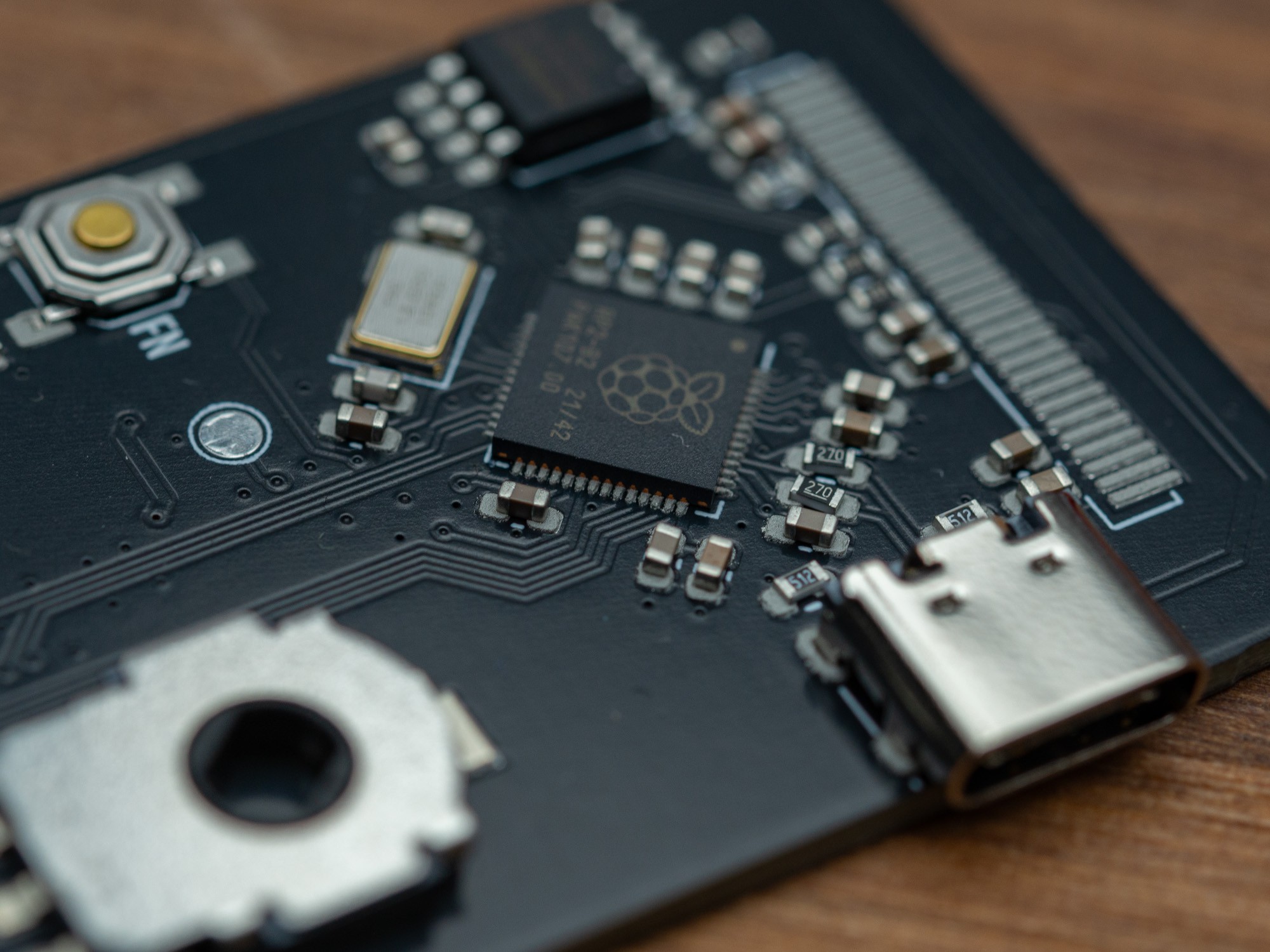
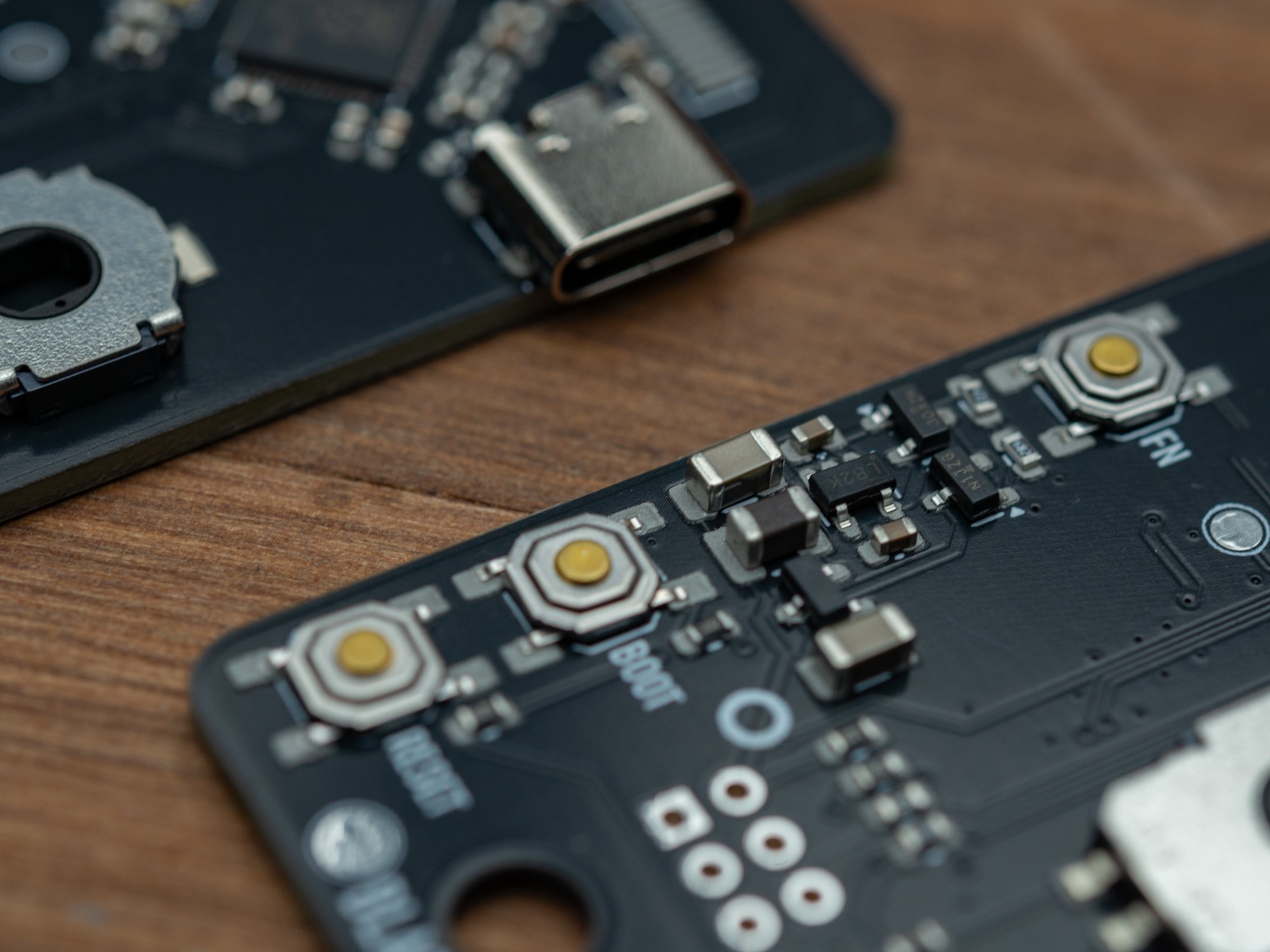
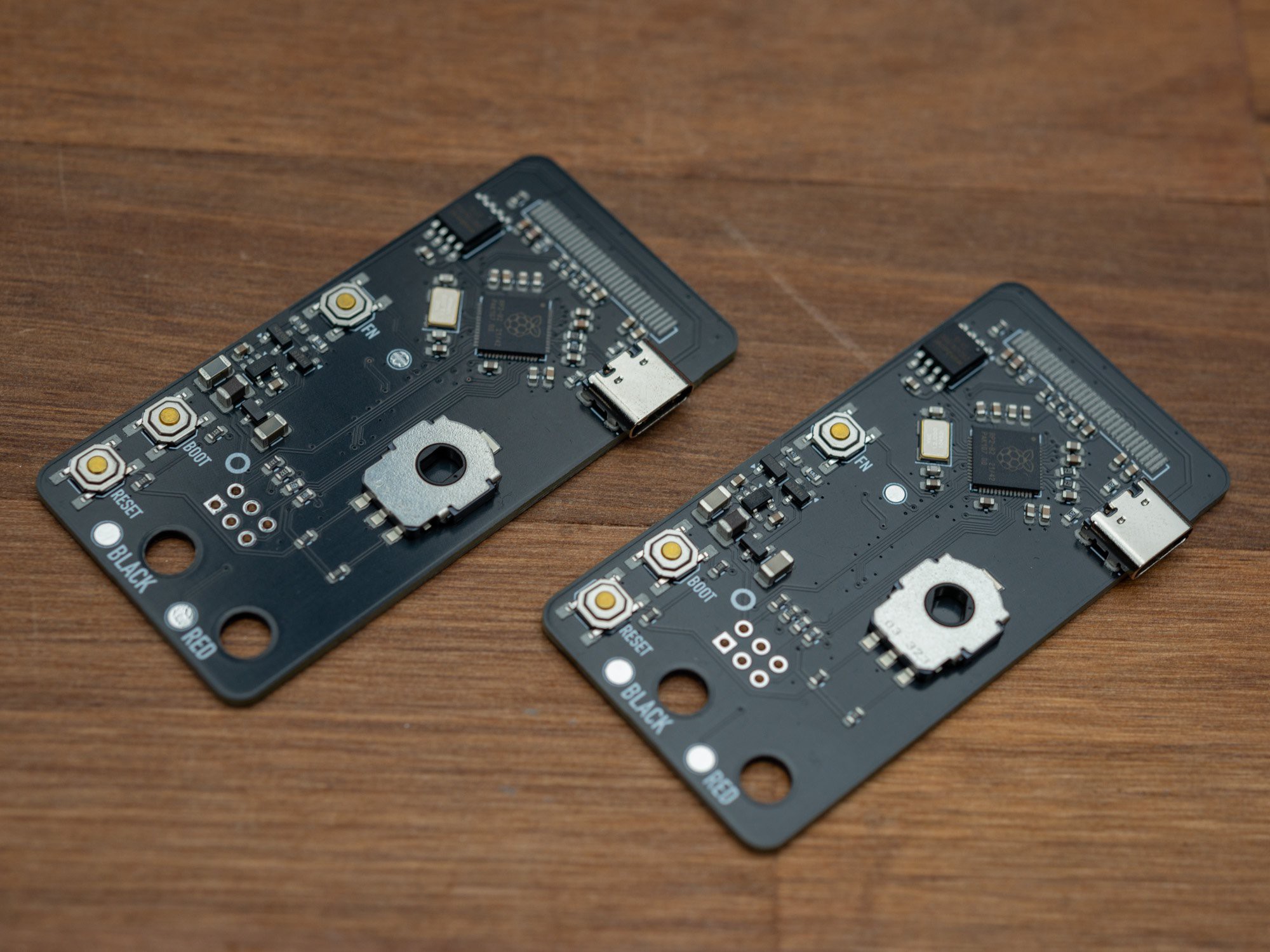
The electronics part of this is essentially a Raspberry Pi Pico (the RP2040) but with a bit more flash and a different power circuit, that can switch between USB power and power from the badge, including boosting a low supply voltage.

In addition, there is an OLED screen, some buttons and a rotary encoder, and some simple resistor dividers for the measurement circuits and not least, a buzzer.

This is of course not the most precise measurement tool, but should get the job done for the simple stuff, like testing LEDs or checking a GPIO pin on the SAO connector.

The front PCB only has the two 2mm banana sockets and the buzzer, all other electronics are on the base board for easy, single sided SMD assembly. Connection between the two PCBs are via 3 spring loaded "pogo" pins.

Firmware

To ease quick development cycles and some sort of compatibility with other projects is this space, the firmware will be based on either MicroPython or CircuitPython, currently running the latter.

User interface should be simple and primarily via the main mode selection knob as on most multimeters, with sub function selection using the Fn button.

For specific functionality (eg. showing up as an I2C peripheral with a specific address), would most likely be a task done via editing the python code via a USB connection.

Case design

The case is a unibody 3D printed part, where the front PCB is closing the box off and holding all the parts inside.

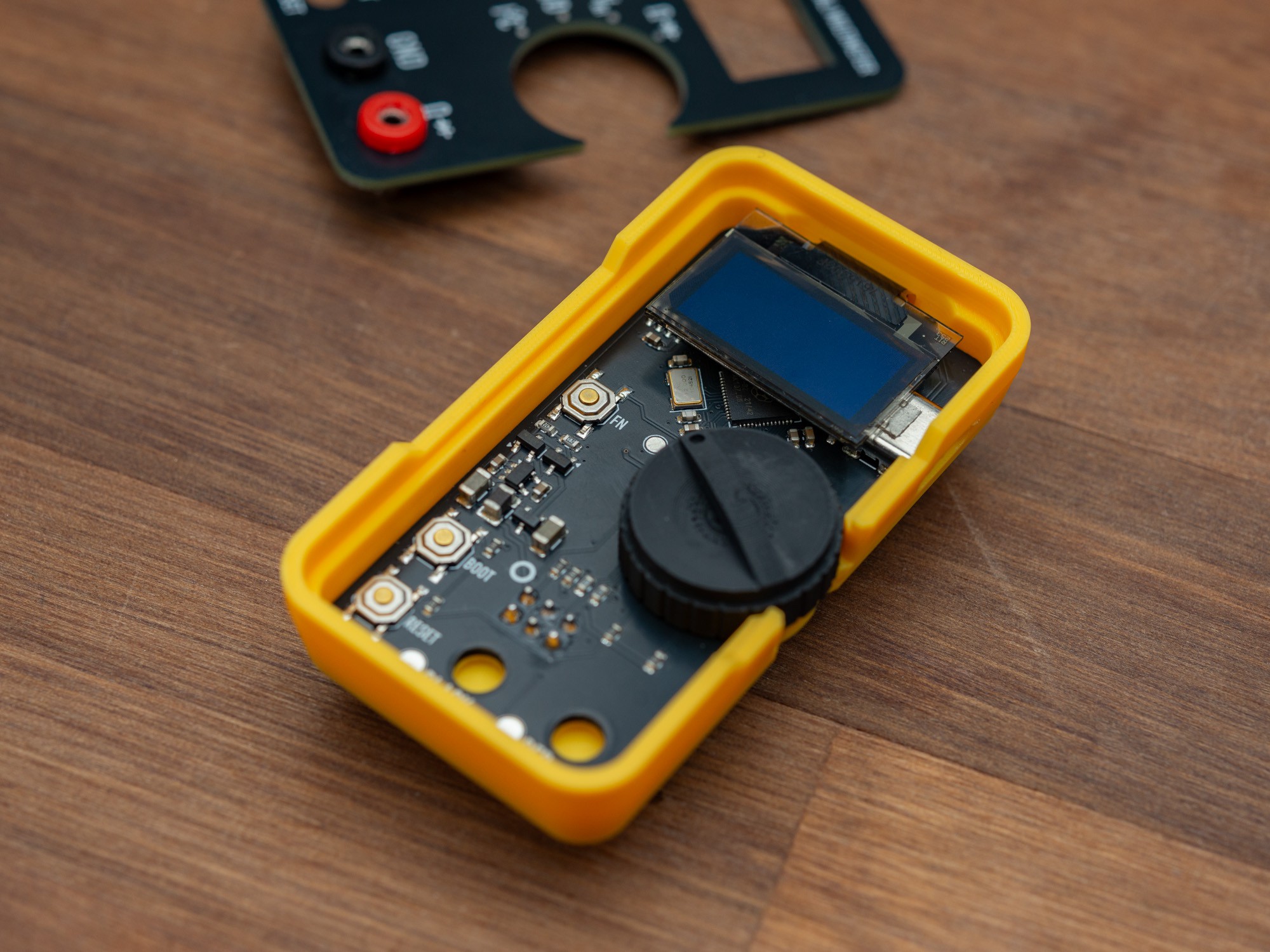
The base board simply sits in the bottom with a slightly loose fit, and to prevent if from moving, a small spacer is placed right above the SAO connector, as that is typically where one would press to mount the SAO DMM on a badge.

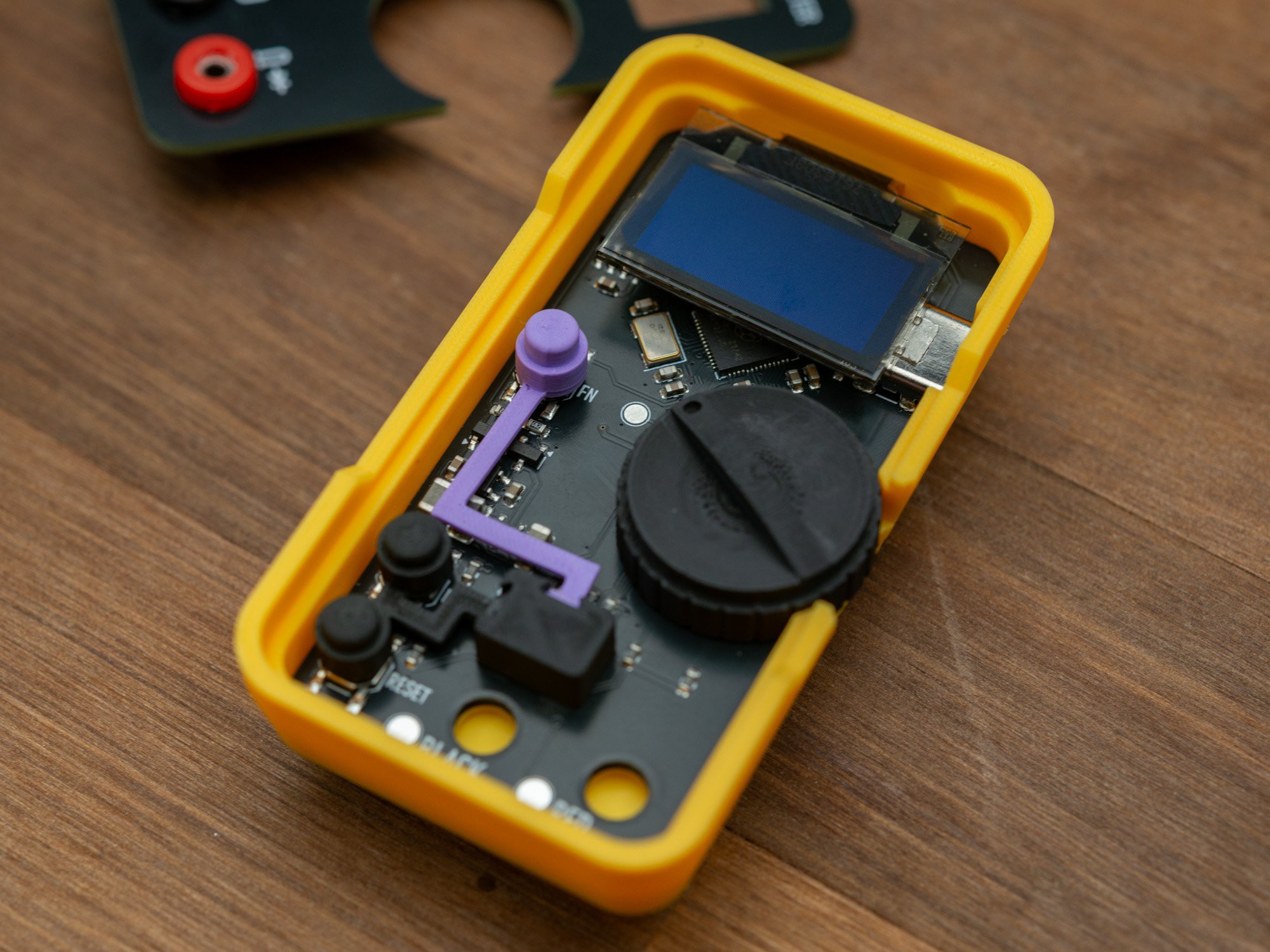
That spacer is also used as an anchor point for the button caps, to help position those for assembly.

The Fn (function) button is raised above the frontplate, where the two system buttons (boot and reset) are pretty much flush with the surface to prevent accidentally pressing them, but high enough to not need tools to press them when needed.

Main mode selection knob

The main mode button misuses a low profile, low resolution rotary encoder, and only uses a third of it's rotation, as that allows "absolute position" from the two output pins. It's not mechanically blocked, so it can do a full rotation, eg. if needed inside a menu or similar, where main mode selection isn't needed.

The encoder is of the smooth type, so no stops, but those are achieved via a small steel ball embedded in the case and little indents in the bottom of the mode selection knob for every 30 degrees. Being held together between the two PCBs, this works surprisingly well, with a good feel for the stops.

SAO Cable extension

As this SAO has a case, that sits behind the PCB, there is less space between the SAO and the hosting badge, which in manu cases isn't a problem, as the connector is often on the front of a PCB in the upper part of a badge, but for those badges with an enclosure, the connector is often inset and not all SAOs will fit directly, including the DMM SAO.

For that, I have designed an extension cable, that uses IDC connectors and a flat ribbon cable to connect to the SAO, with a small PCB and a handle for easy connect and disconnect.

SAO Contest details

This SAO is a little bigger than the specified max size (in total, including case, it't 41x75mm), but it's actually not THAT difficult to manufacture, though there is a...

Read more »

DMM SAO Schematics.pdf

Adobe Portable Document Format - 244.16 kB - 10/22/2024 at 13:03

Preview

  • Case and button design

    Thomas Flummer10/22/2024 at 14:08 0 comments

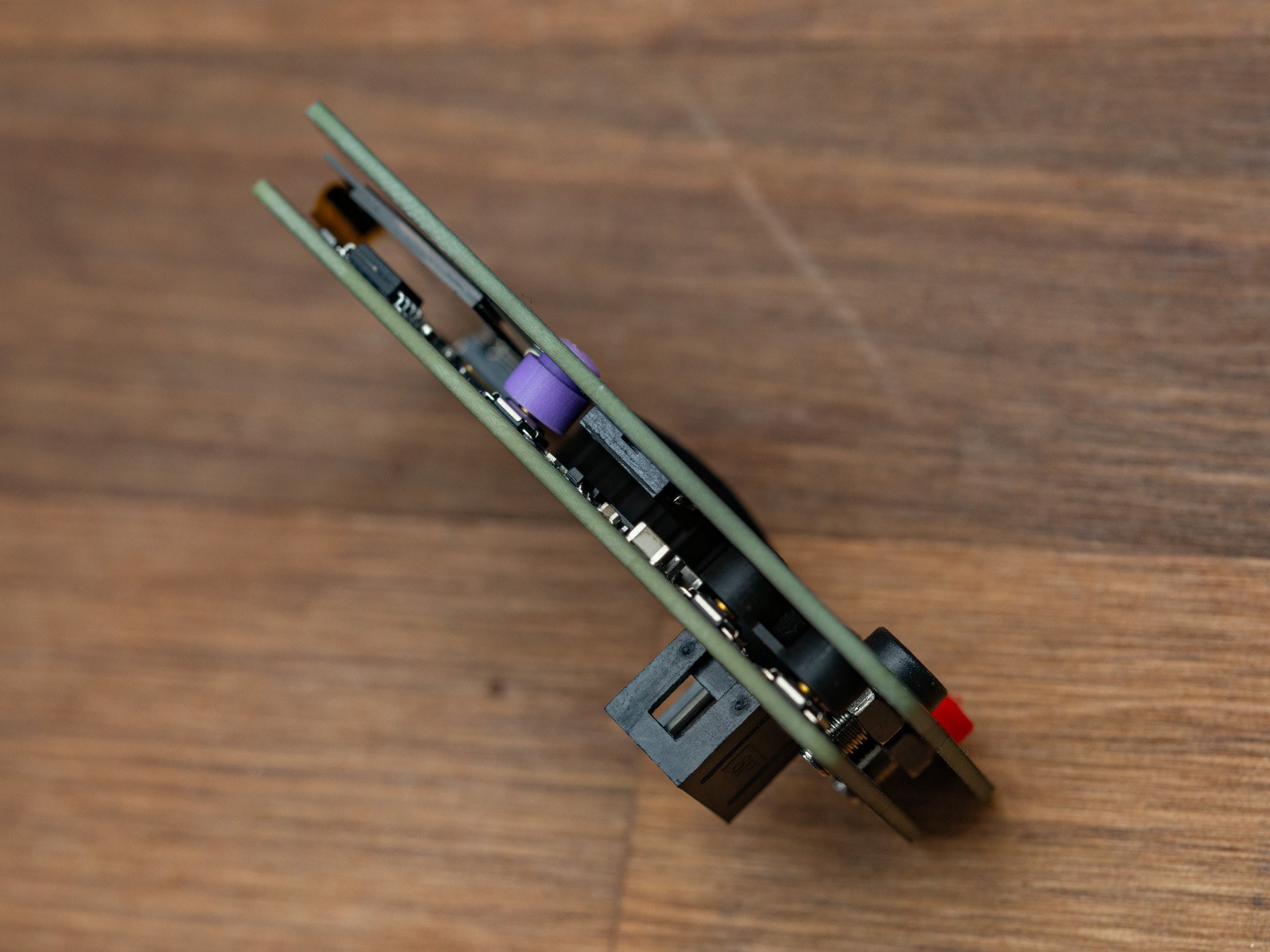
    The electronics is sandwiched between the base PCB and the front plate. In between are all the components, screen and the button caps and the main mode selection knob. Only the SAO connector sits on the back.

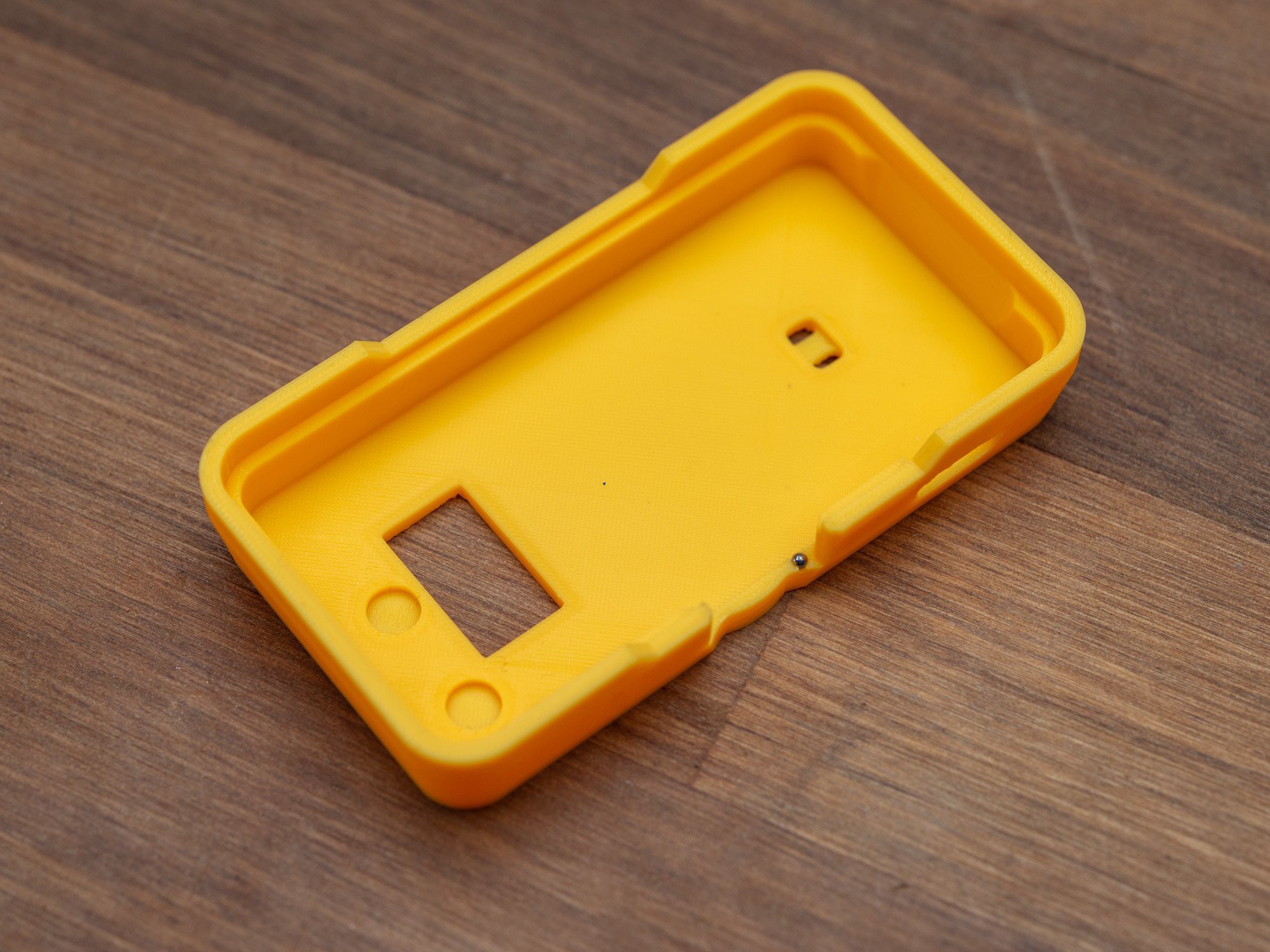
    The case has a cutout for the SAO connector, small indents for the two 2mm banana sockets, and two small holes, to add a SAO leash, as an extra protection agains loosing a SAO that falls off a badge.

    To have the screen sit correctly, the top of the case has been extended a little, to accommodate the flex pcb that connects it to the base board.

    The distance between the boards is just enough to have the screen sit on top of the USB-C connector, about 4.9mm.

    As the rotary encoder does not have stops but rotates smoothly, firm position locks are done by adding a small (Ø1.5mm) steel ball inside the case side, and adding indents for every 30° on the bottom of the knob. When the knob is squished between the two PCBs, this makes for a pretty decent feel.

    The knob has small ridges on the outside, for better grib when using a thumb or similar to rotate.

    The button caps are held in place by thin printed extensions, that connect to the spacer, that sits directly above the SAO connector, preventing the bottom PCB from moving in the case, especially when inserted into a badge.

  • PCB assembly time

    Thomas Flummer10/22/2024 at 13:30 0 comments

    I generally get stencils for all projects, and use the interactive HTML BOM for assembly, combined with a camera based microscope to check orientation and proper placement.

    For the majority of the parts, I use a small curved tweezer (Erem), and some of the larger ones could simply be positioned by hand (rotary encoder and USB-C connector), as there are alignment holes for those.

    Two base boards ready for baking

    I use one of these small hotplates... it a bit on the small size for this, but moving the PCB a little made sure all got soldered. Compared to the regular cooking hotplate I was using before, this is MUCH more stable with the temperature, and stays at 210°C only dips a little when I put on a new PCB (probably not the best thing to do, but I'm to impatient to wait for it to cool down)

    The OLED displays are soldered on with a soldering iron and the solder that was applied during pasting. It might have been a little too much solder, as I had to redo it on one of them due to a short.

View all 2 project logs

  • 1
    PCB Assembly

    As some of the parts have a somewhat small pin pitch and some parts don't even have legs sticking out (RP2040 QFN), going with a stencil for solder application and then adding the parts is probably the way to go.

    Base PCB is single sided, and all other components can be handled with a soldering iron (buzzer on frontplate PCB, SAO connector and the OLED screen). The two 2mm sockets will simply screw in to the faceplate.

  • 2
    3D printed case and buttons

    The 3D printed parts, especially the small buttons and the rotary knob, will need a fairly decent 3D printer. I printed all with a 0.2mm nozzle and used adaptive layer height for the button caps and the knob. The slightly curved top surfaces ends up a bit stepped if not. The small steel ball for the rotary knob notches needs to be pressed into the small hole. It might be a little tricky.

  • 3
    Putting it together

    With the base printed and the PCB's soldered, the base PCB drops into the bottom, fold down the screen and give it a tiny piece of double sided tape on top of the USB-C connector to hold it and then add the knob and the button caps. Finish off with putting the face plate on there and squeze it in. It's a tight fit, but should stay put.

View all 3 instructions

Enjoy this project?

Share

Discussions

michimartini wrote a day ago point

I have never heard the term "SAO", what does it mean?

The design is very beautiful, the reduction to the necessary is very relaxing to look at. 

  Are you sure? yes | no

Thomas Flummer wrote a day ago point

Thank you for the nice words.

SAO is short for "Shitty Add-On" or the PG rated "Simple Add-On"... for Supercon, it was renamed to "Supercon Add-On", but it's all the same.

It's a standard for little add-ons that can be attached to electronic event badges, that follow the standard.

This DMM focusses on the features related to this connection standard and other simple features (resistance/led/continuity).

  Are you sure? yes | no

jeremy.geppert wrote 10/25/2024 at 12:44 point

This is brilliant! You nailed the aesthetic but also functionality. This is inspiring.

  Are you sure? yes | no

true wrote 10/22/2024 at 13:36 point

for testing continuity, the only way I am seeing this done on your design is via 3v3 and 100ohm dropper resistor. this means potentially frying low voltage circuits if using your tester on a board with supplies lower than 3v3. at least it'll be current limited...

my entry for the contest with continuity test uses 1.24V and about 1Kohm in continuity mode. it also has high voltage protection so it should be OK for testing on circuits with up to about 20-30V present. I just uploaded the schematic if you want to see how I did it.

  Are you sure? yes | no

Thomas Flummer wrote 10/22/2024 at 13:42 point

Yes, all the measurement stuff is hacky at best, but hopefully good enough to be useful and/or fun.

  Are you sure? yes | no

Similar Projects

Does this project spark your interest?

Become a member to follow this project and never miss any updates