Close
0%
0%

ESP32 Game Console

This is clone of the Odroid Go game device with upgrades

Similar projects worth following
Starting from
$49.99
dronecz83 has 129 orders / 13reviews
Ships from Czechia
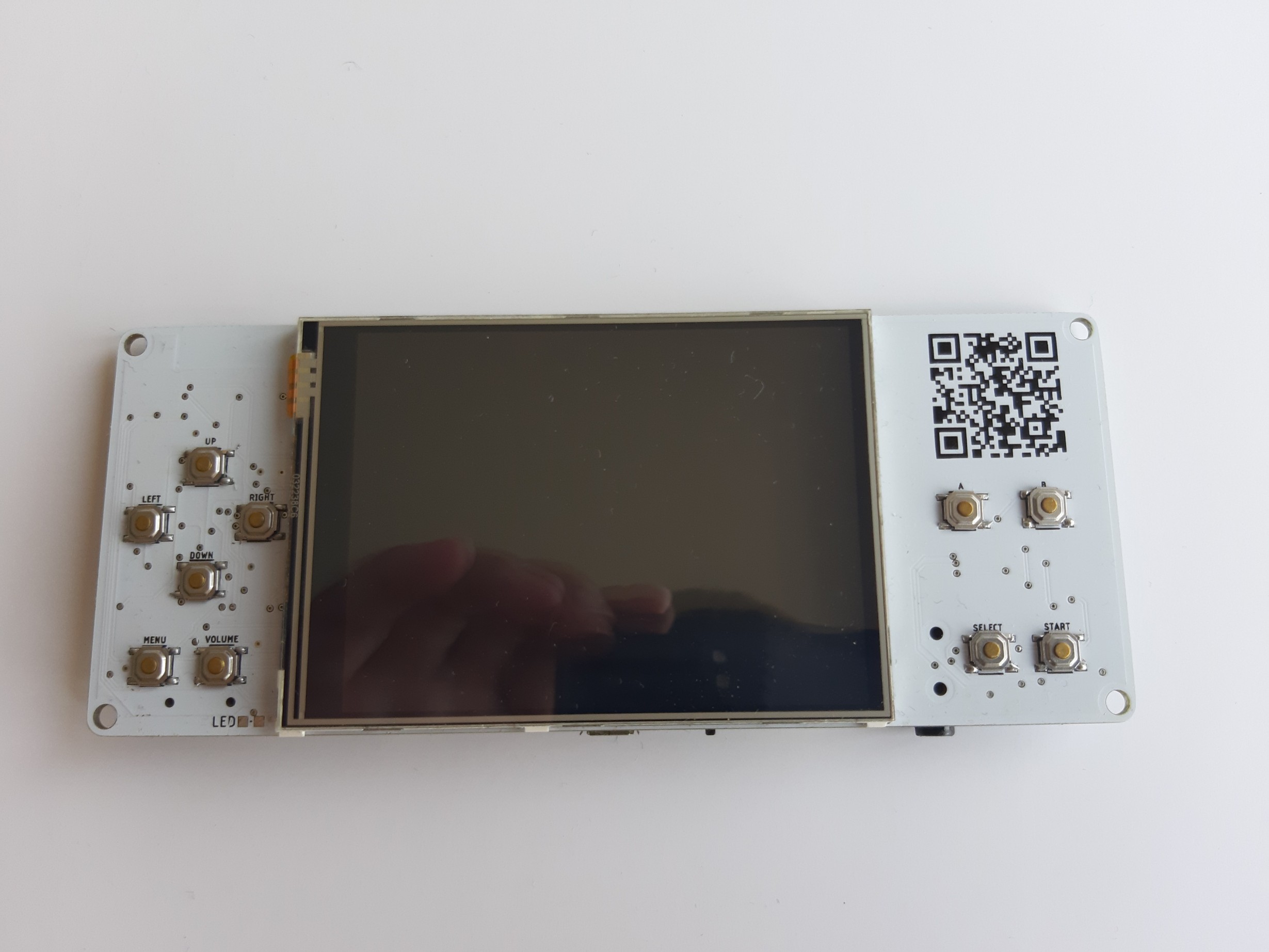
Once upon a time, when I was browsing internet, I saw this nice ans simple game device based on ESP32. I searched a bit about it and did find out that it is quite popular and can be hacked/used with Arduino IDE. When I saw pricetag and shipping, I decide to make my own so I can try it and learn something new. Here, in logs, is my journey..

This is should be direct clone of Odroid Go (fully compatible) with some added features:

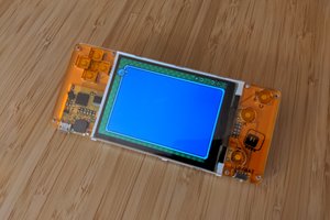
  • 3.2" ILI9341 TFT LCD
  • ESP32 WROVER with PSRAM (16MB)
  • micro SD card 
  • built-in charger based on MCP73831
  • integrated audio through PAM8304
  • integrated I2S audio through MAX98357 (early version was with PCM5102)
  • 3.5 mm audio jack 
  • 2000 mAh Li-Po battery
  • USB to UART via CH340G

This game console can be programmed with examples from Odroid Go library or you can use this library to program your own games. This can also be used with Micropython.  

  • 1 × ESP32-WROVER-B (16MB) main MCU
  • 1 × MAX98357 Audio ICs / Audio Amplifiers
  • 1 × PAM8403 Audio ICs / Audio Amplifiers
  • 1 × CH340G USB to UART converter
  • 1 × ILI9341 3.2" LCD

View all 6 components

  • Write-up

    Miroslav Zuzelka05/23/2020 at 08:59 1 comment

    To be honest, i started this project because I did not want to pay about $80 for console and shipping to Czech Republic. If I look back, it cost me much much more, but it would not be such a fun & and some frustration. It took me about 1,5 year to finish this project, but I had some delays between board revisions, it was not constant designing, building, fixing mistakes. 

    If you would ask me if I regret it, to dive in this rabbit hole, I would definitely say "No" as this was very good learning journey from maker perspective. I can not say that I build this from scratch as I would have to design schematic and also write firmware. I think and I hope this proves power of the open source as you can take something what someone else build and make it in your way, better, worst or just for fun, 

    I think that I accomplished my goal and I made my console "better" than original piece of HW. I know that you can now buy Odroid Go Advanced, which is much more powerful than OG and you can play more emulators than on OG, but I did not build this for business as I would have to build this much more faster and in higher quantity. 

    I´m happy that I finished this and I will put all my design files (for PCB and for 3D printed case) at my Github so if anyone want to build their own, they can just order PCB´s, parts and have same fun as I had. 

    I will also sell some in my Tindie store as I do not need 20 pcs of this :) . I hope this was not boring reading and you enjoyed my journey, at least a bit. 

  • Revision F (probably last revision)

    Miroslav Zuzelka05/23/2020 at 00:52 0 comments

    If you read my previous logs, I wrote that I do not want invest more time and money in to this project, but destiny probably thought differently. 

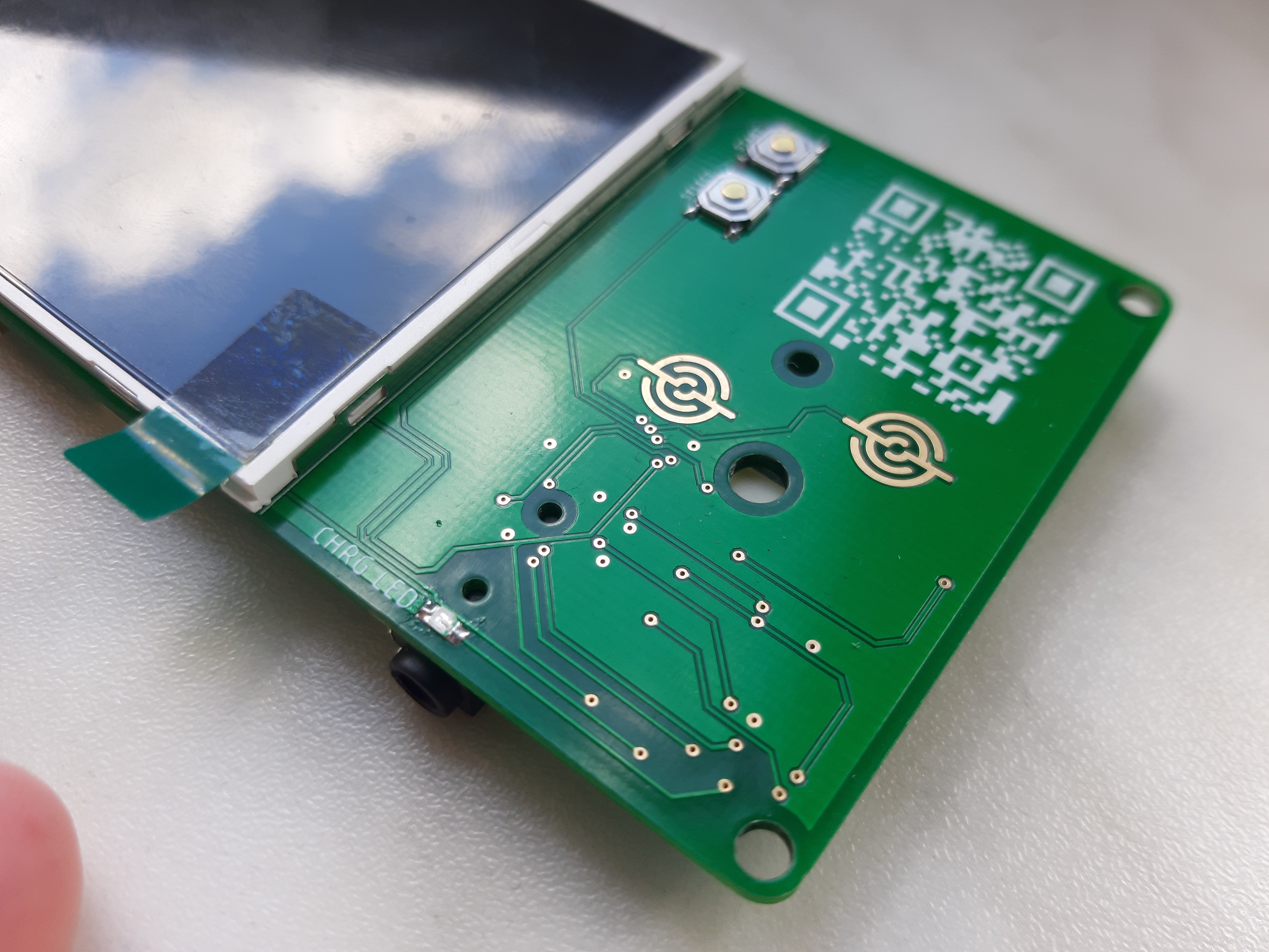
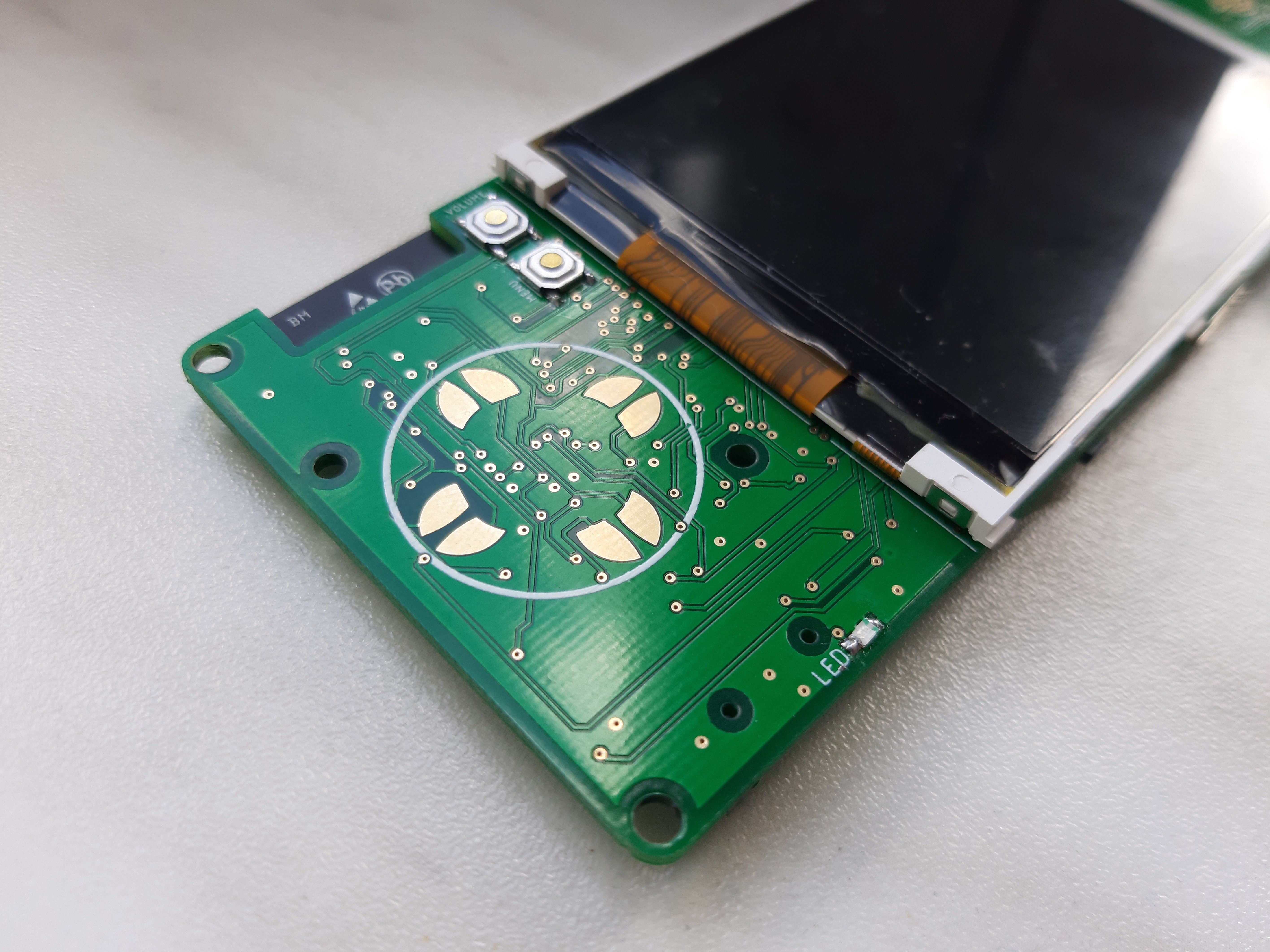
    When I found this awesome Stephen Hawes channel at YT I was already engaged in my 3D printed pick and place machine project and I was looking how to solve problem with feeders for it, but in one of his videos he speak about uneven plating on the PCB and in that moment I knew form where my problem with conductive buttons is coming. If I do not have flat pads for these buttons I can have "ghost" presses or even none existing pressed as rubber buttons do not have enough space to make proper contact with PCB. After this I decide to give this project one last try. 

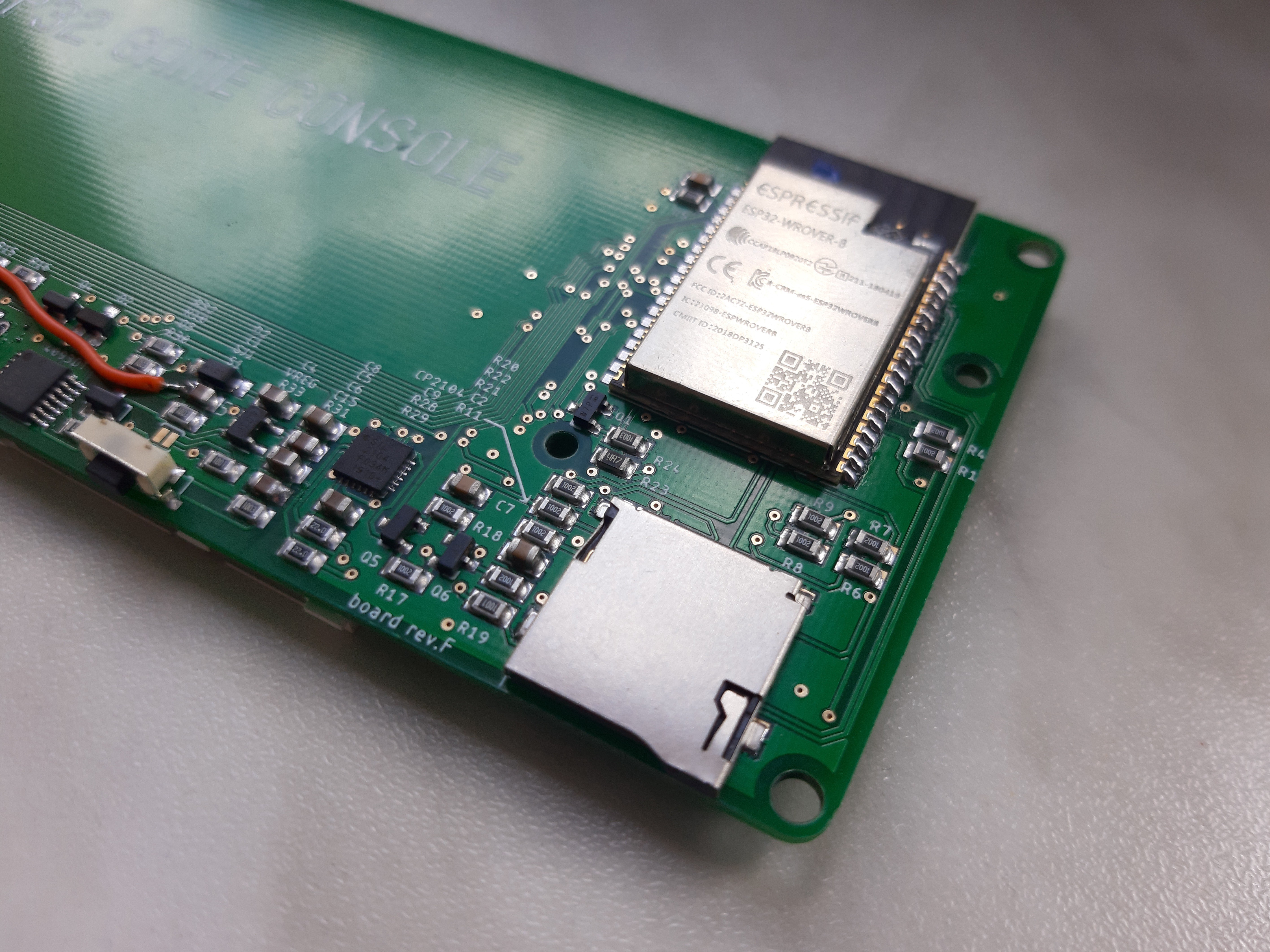
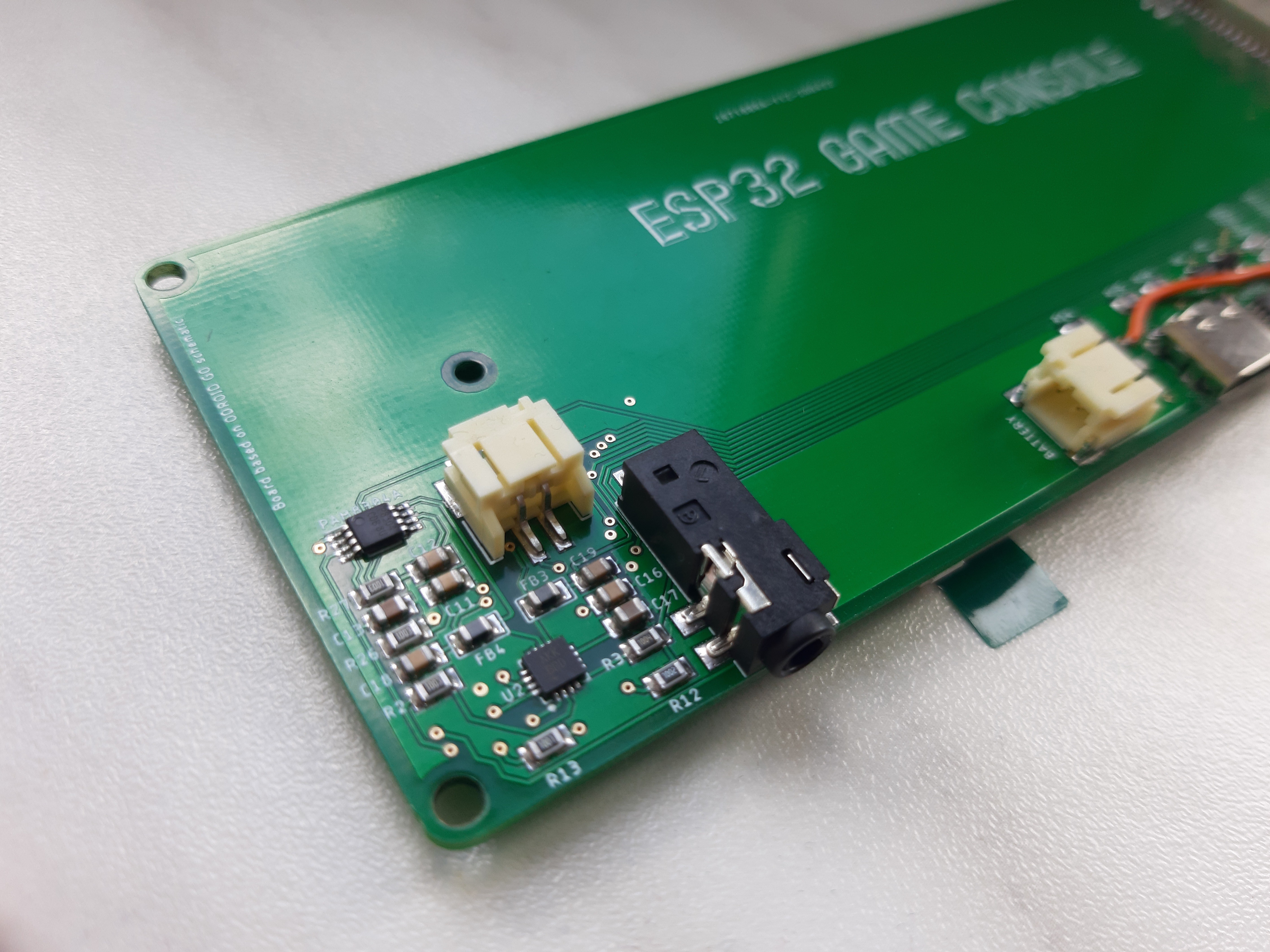
    Because I already moved from micro USB connector to USB-C connector in my ESP32 Reflow oven project, I decide put USB-C to this board as well. Other thing which I added, and think is quite cool, is power button in micro switch form instead of the sliding one, which I used in previous revisions of my board. Last part which I replaced was UART chip, as I had no stock of CH340G and did not want to wait for them to arrive from China, for CP2104 which is popular and used on many boards but can be very easily ordered from any big electronic store as TME, Mouser or Farnell.

    i knew from previous assemlies that it is not much space around I2S chip, so I rearrange all components f that part and make a lot of space around this chip in case that I have to rework something with soldering iron.  

    Because gold plating (ENIG) is bit more expansive than HASL I ordered 20 of these boards to make price for 1/pc in reasonable range. As I made big order for PCB I was worried that this will slow down delivery as production can be longer than PCB´s with HASL (4 days in compare to 1 day), but from what I saw at JLCPCB page in production report, it was pretty fast. I think as fast as PCB´s with HASL.

    I also ordered stencil with PCB´s, which make assembly of the boards much more easier. As usual, I assembled one, checked continuity between 5V -> GND, 3V3 -> GND and repaired few solder bridges. I populated just bottom side as on top side are just 2 LED´s, 4 buttons and LCD screen and this is not worth it or can not be done in oven. 

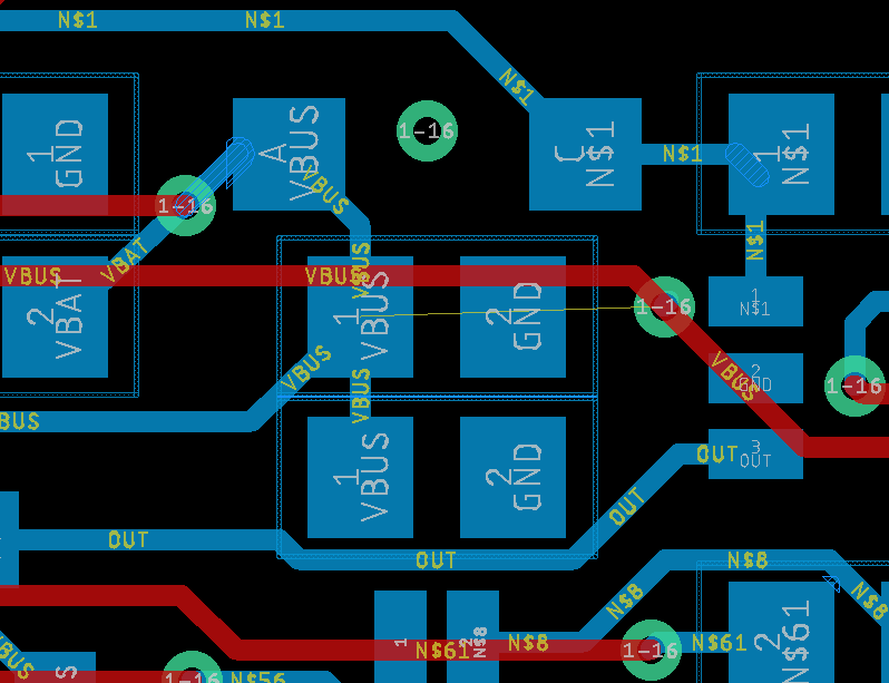
    I inserted USB cable in the connector, press the powr button and NOTHING! It should make connecting sound (same when you plug USB device in USB connector), but did not beep :( . I fired up Eagle to look where I should start debugging and when I was checking 5V line, I sawed that I missed one connection between bottom and top layer. I had also one overlap between VBAT and 5V rail,but this could be quickly repaired by knife.

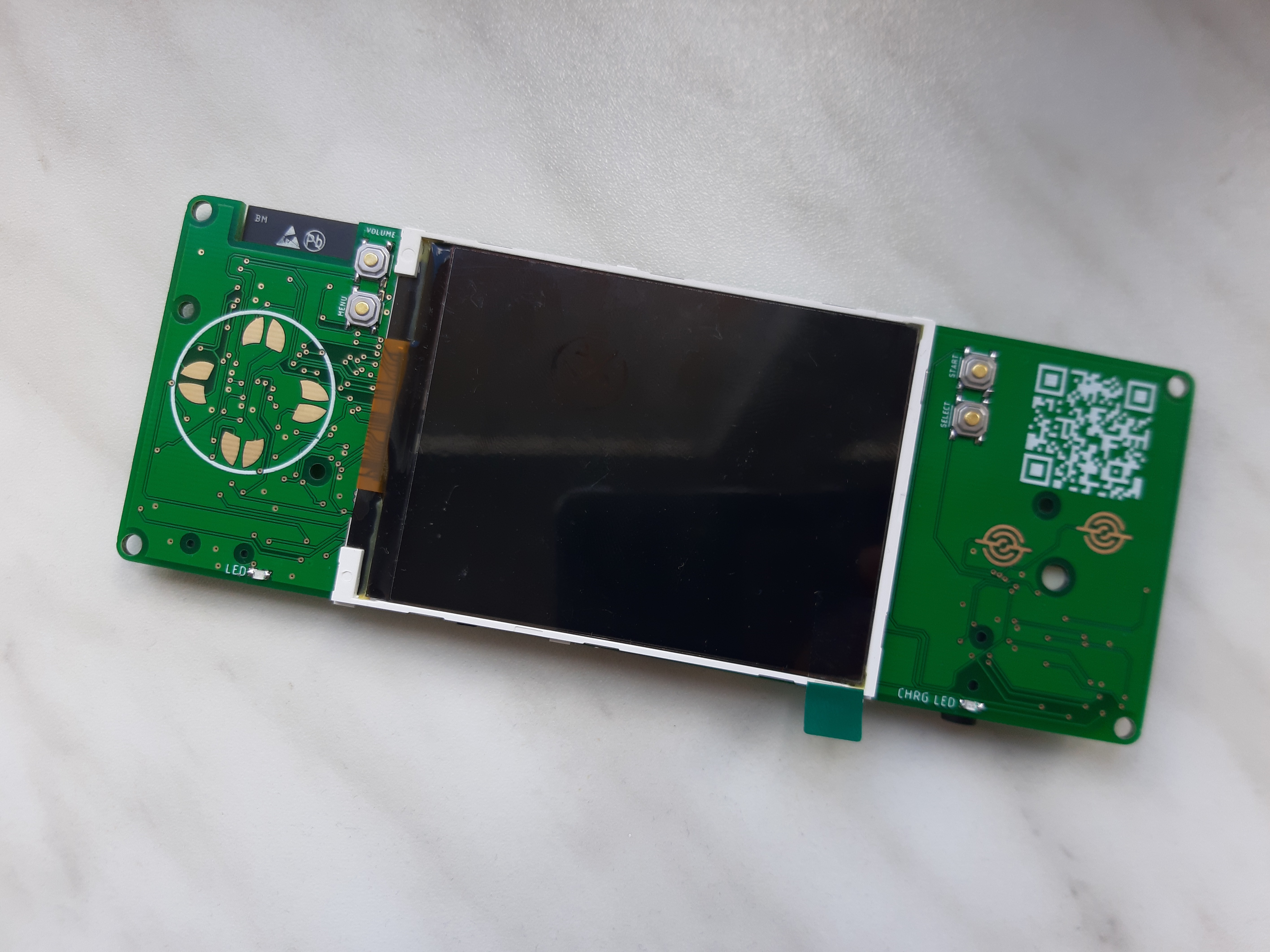
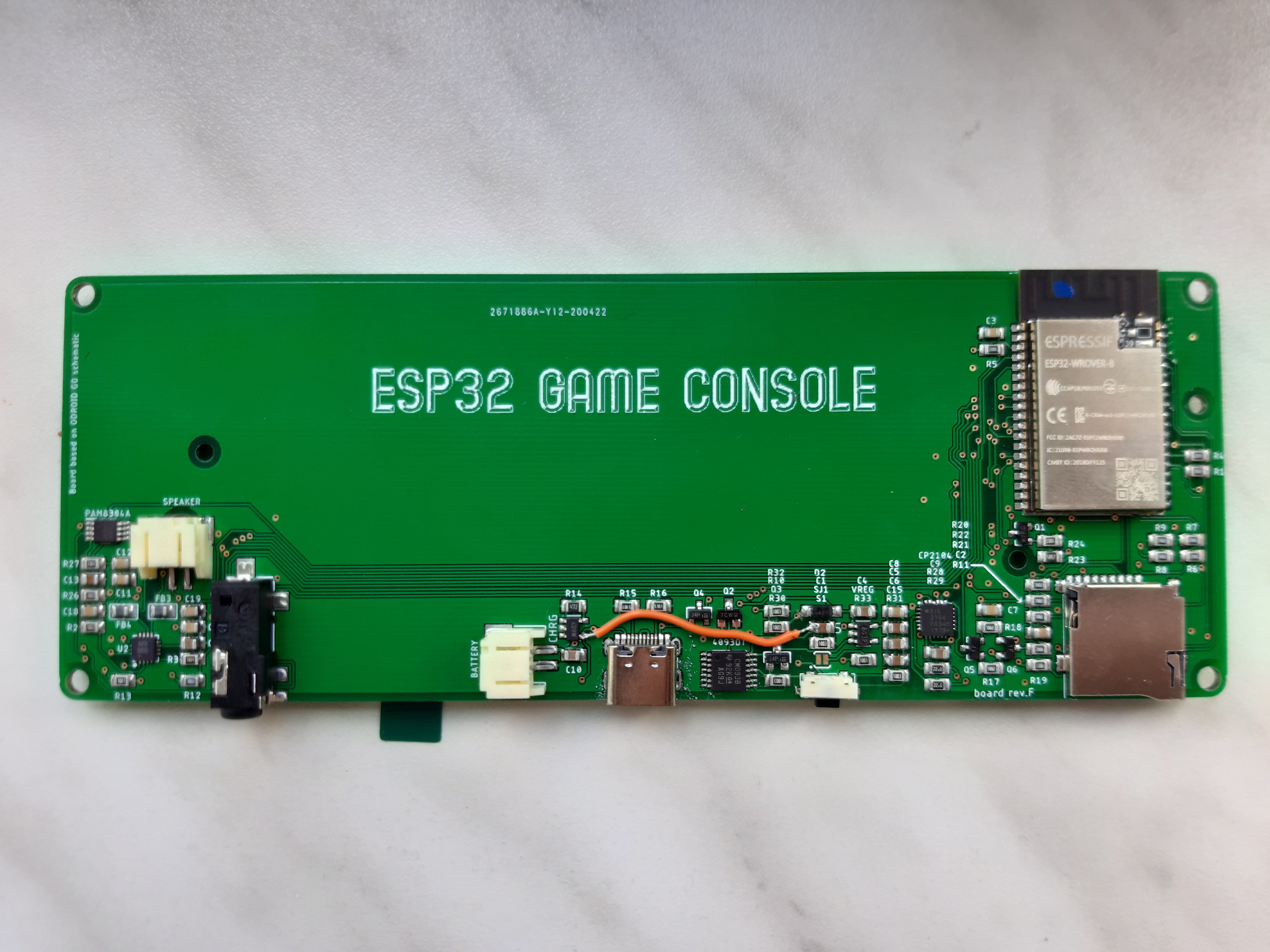
    I repaired missing 5V rail (VBUS) with wire and tryed to fire it up again, this time with success.  i populated top side of the board, programmed bootloader to the ESP32, inserted SD card, flashed right FW and swapped older revision of the PCB for this one in 3D printed case. At that moment I was pretty tense. I fired up Super Mario game (I was always testing with this one) and played a bit and I did not missed single button press! Mario was following my buttons presses without slight problem. To quote Stephen Hawes: "Awesome! What a relief.. :) ". To be sure, I tested different games and did not find any issue. Sure buttons are bit hard, but this could be because they are new or there is small mistake in design of the 3D printed case. 

    Here is finished PCB with bodge wire :) :

    I did not play it a lot, so if i will find out that there is some problem, I will cover it in another log. 

  • Revisions B to E

    Miroslav Zuzelka05/21/2020 at 15:15 0 comments

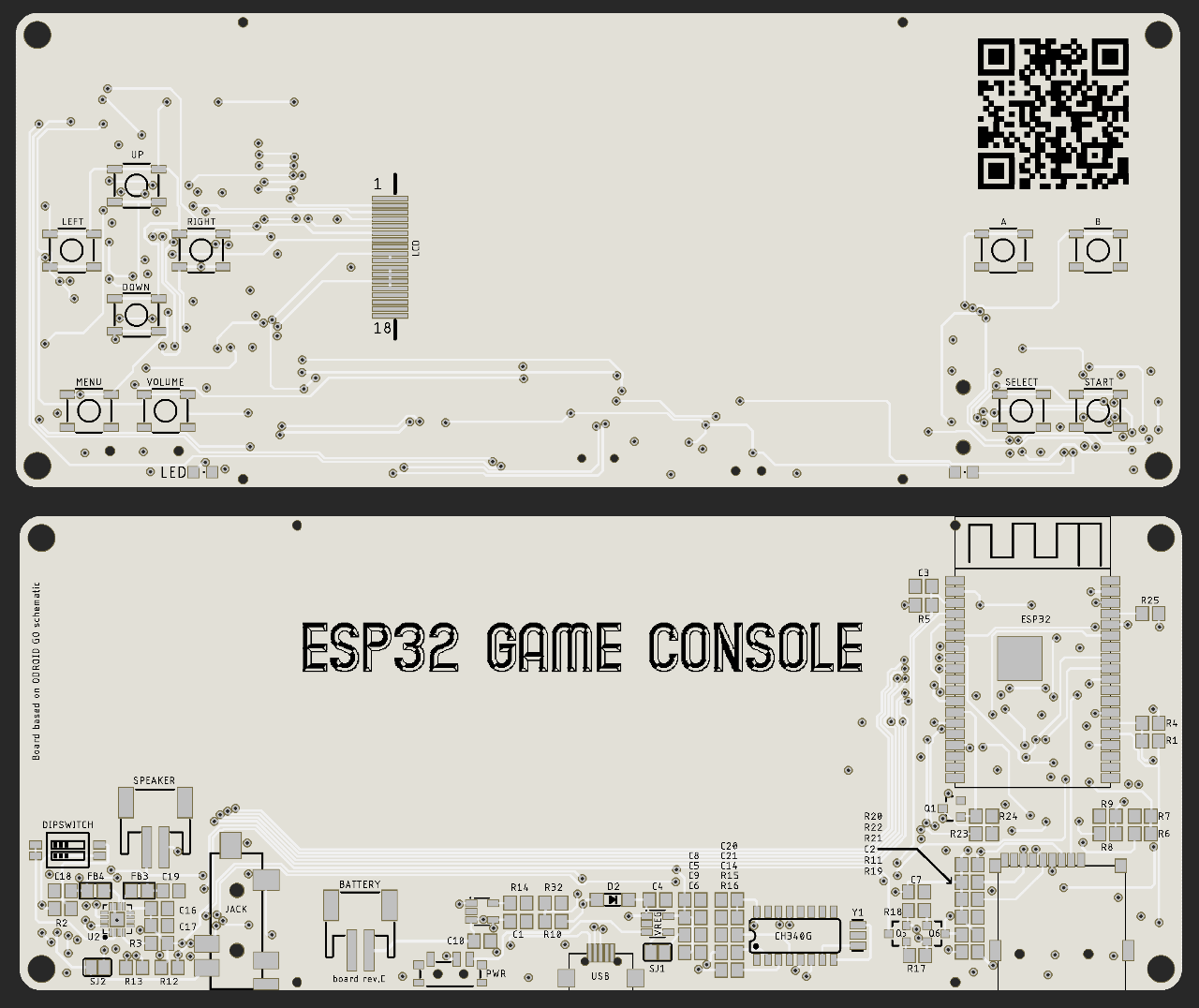
    As I wanted to make my project better and fully comparable to original Odroid Go (OG) a made few more iterations. Because they are not so different from each other, I decide to cover them in one log and describe just changes which differentiate these versions from each other. .

    rev.A -> rev.B :

    This version actually did not make it to the fabrication stage.
    it contained:

    - UART line repair from rev.A
    - SMD 12 MHz crystal instead of that THT one
    - different sound chip than OG has (LM4890) , but should play sound in all games.

    rev.B -> rev.C :

    This version had different I2S sound chip ( I use MAX98357A). I also changed speaker connection from solder pads to JST connector and I added, but actually never used, DIP switches to change output volume of the I2S chip. 

    rev.C -> rev.D :  

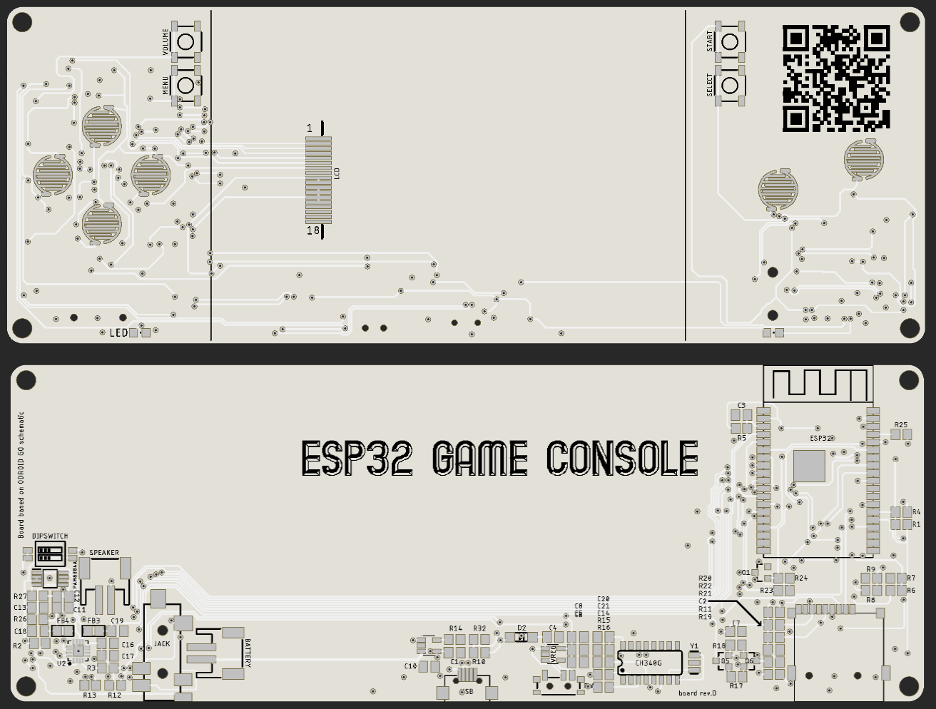
    This is first version at which I used conductive buttons. If anyone will search for some library which can be used, I recommend library (for Autodesk Eagle) from 32teeth (Conductive buttons) .  These buttons are used for D-pad and A & B. All other buttons are still micros switches. 

    Board is bit wider, because I could not fit these conductive buttons on the side of the LCD. I also moved all other buttons to top side of the PCB and arrange them vertically on both sides of the LCD, where they are not in way when someone is playing. 

    In this revision i used original sound chip from OG and same I2S chip as in rev.C . I also changed position of JST connector for battery, I moved it near to the audio jack connector at left side. 

    To make it work, I ordered rubber buttons from China for Gameboy. Because is quite hard to find some dimension for Gameboy (GB), I had to order spare case as well and when this arrive, I took measurements and put them in my design for 3D printer. 

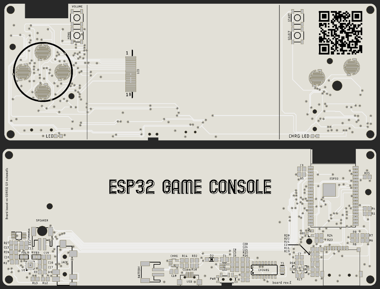
    I assembled one of the boards and everything worked, but I had some problems with buttons. They fully worked if I pressed Right and Down button, but if I pressed Left and Up, they worked just sometimes. I was thinking that problem could be with different accuracy of the resistors (from original OG design) but I looked what accuracy I used and those resistors were 1% accuracy, so this could not be the case. I made few iterations of the 3D printed case and with one iteration, buttons worked almost perfectly so I toughed that this was just issue with placement of the rubber pads to the PCB. To support best alignment of the rubber buttons and PCB I looked at case for GB and add holes which are at original PCB of GB as well. All these changes are reflected in revision E.

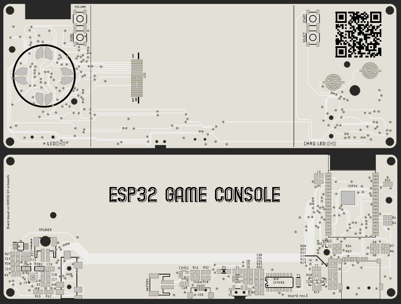
    rev.D -> rev.E :

    Because I was not completely sure that my problem with bad button presses was 100% related to the placement of the rubber buttons and PCB, I made 2 version of this revision. First, which had all conductive buttons of the same design and second, which had conductive buttons for D-pad same as original GB. I also made two other changes. Firstly I moved JST connector for battery back to the middle of the PCB,  as cable from battery was not bend in right way, when battery was inserted. Second small change was cut out for power switch, as this was hard to operate, when case of the console was put together.

    When I received boards, I assembled one and start testing. Alignment holes helped, but presses were still unreliable. Pressing Left/Up mostly worked but it was not consistent. To test, where are rubber buttons touching the PCB, I colored them with black marker, inserted them with PCB in the case and pressed them. This showed me that I have to move D-pad holder down about 0,5 - 1 mm, but after few iteration of the case, problem still appears. At this point I decide that I will not invest more time and money with this project and put all in the drawer.  

  • First version - rev.A

    Miroslav Zuzelka08/08/2019 at 22:53 0 comments

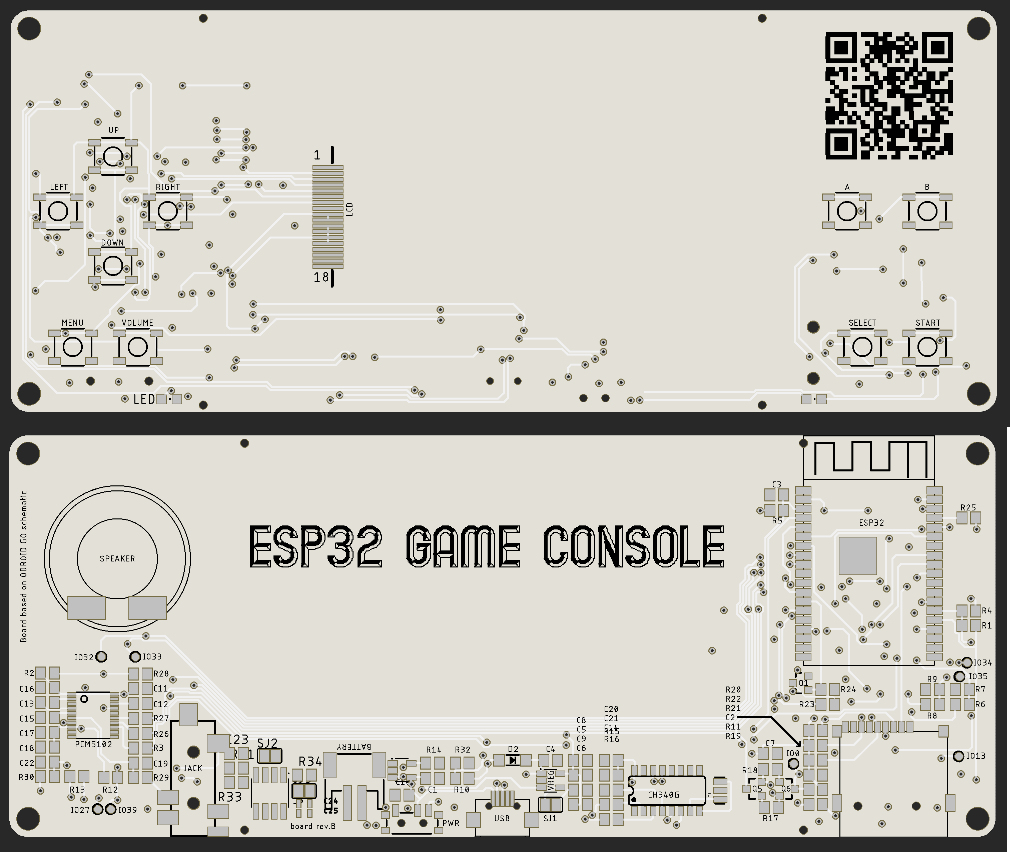
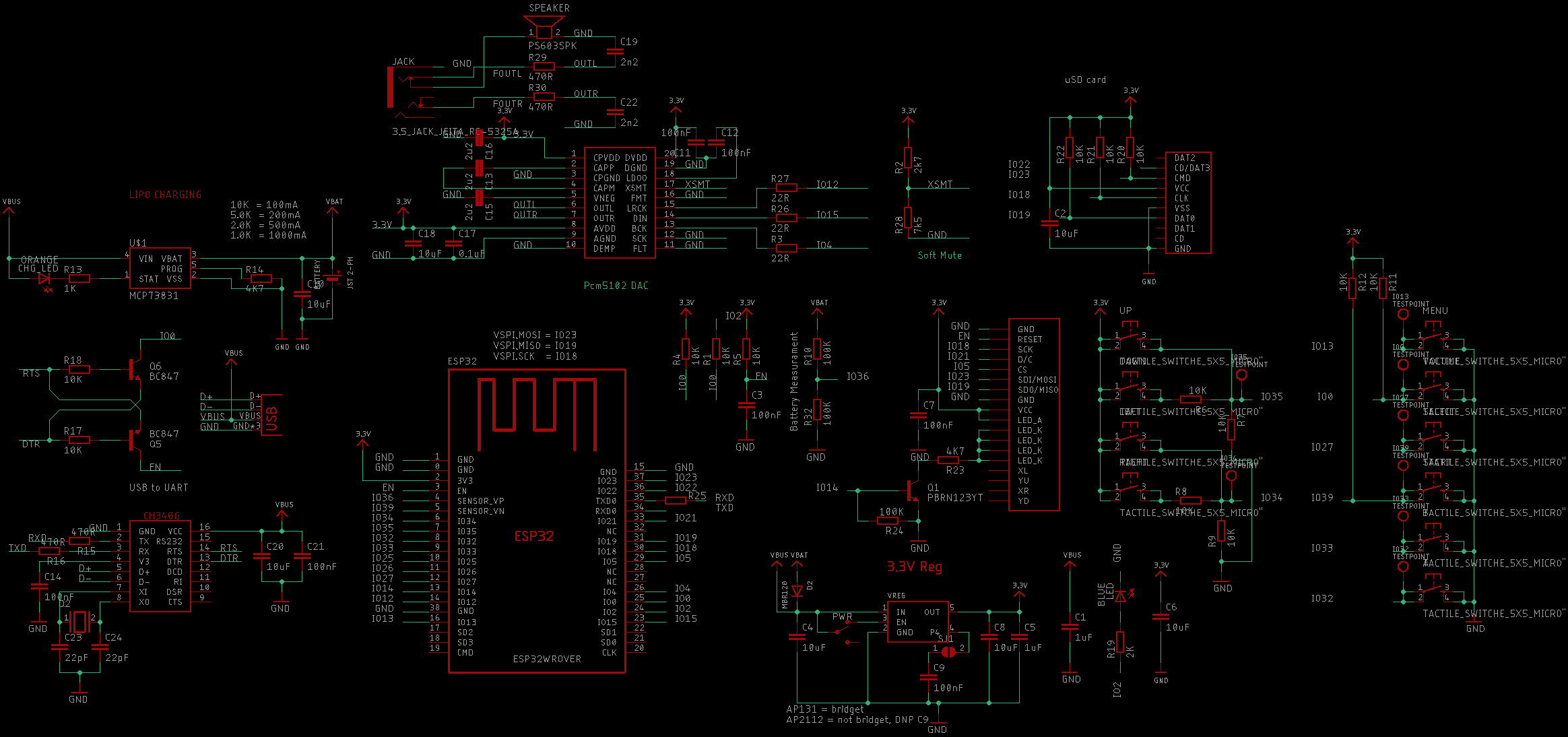
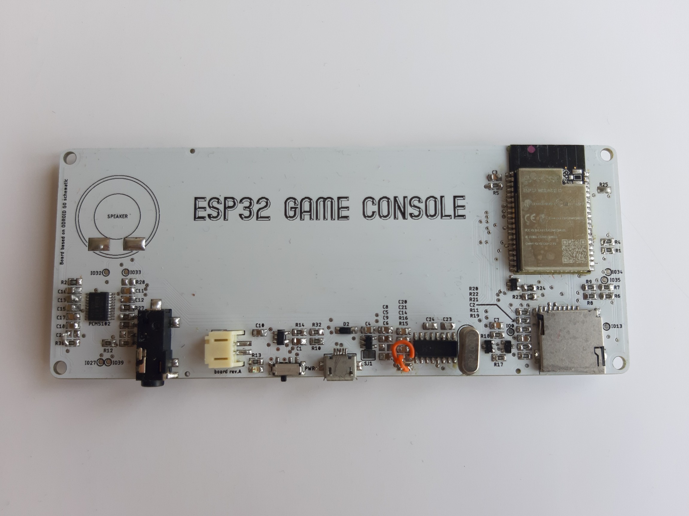
    Now, when I gathered all information which I need, I can design PCB. My goal was to make this better than original piece and I did read somewhere that original sound is quite bad, I decide that I will not use original sound chip and I will upgrade it to PCM5102 which is I2S chip and it was already supported by original FW of the Odroid Go (OG). 

    Here is schematic: 

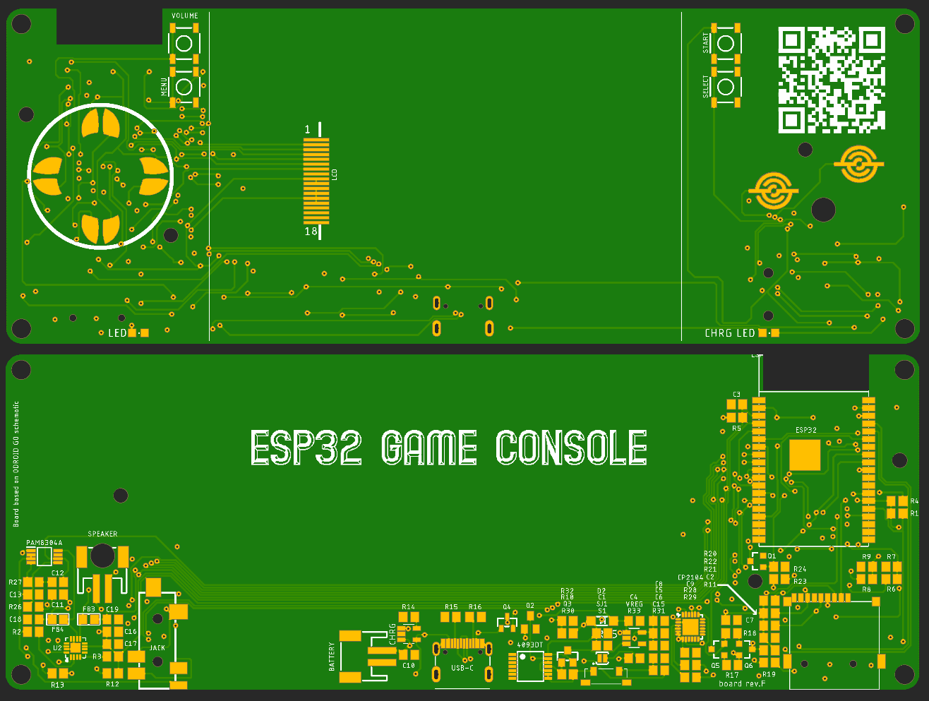
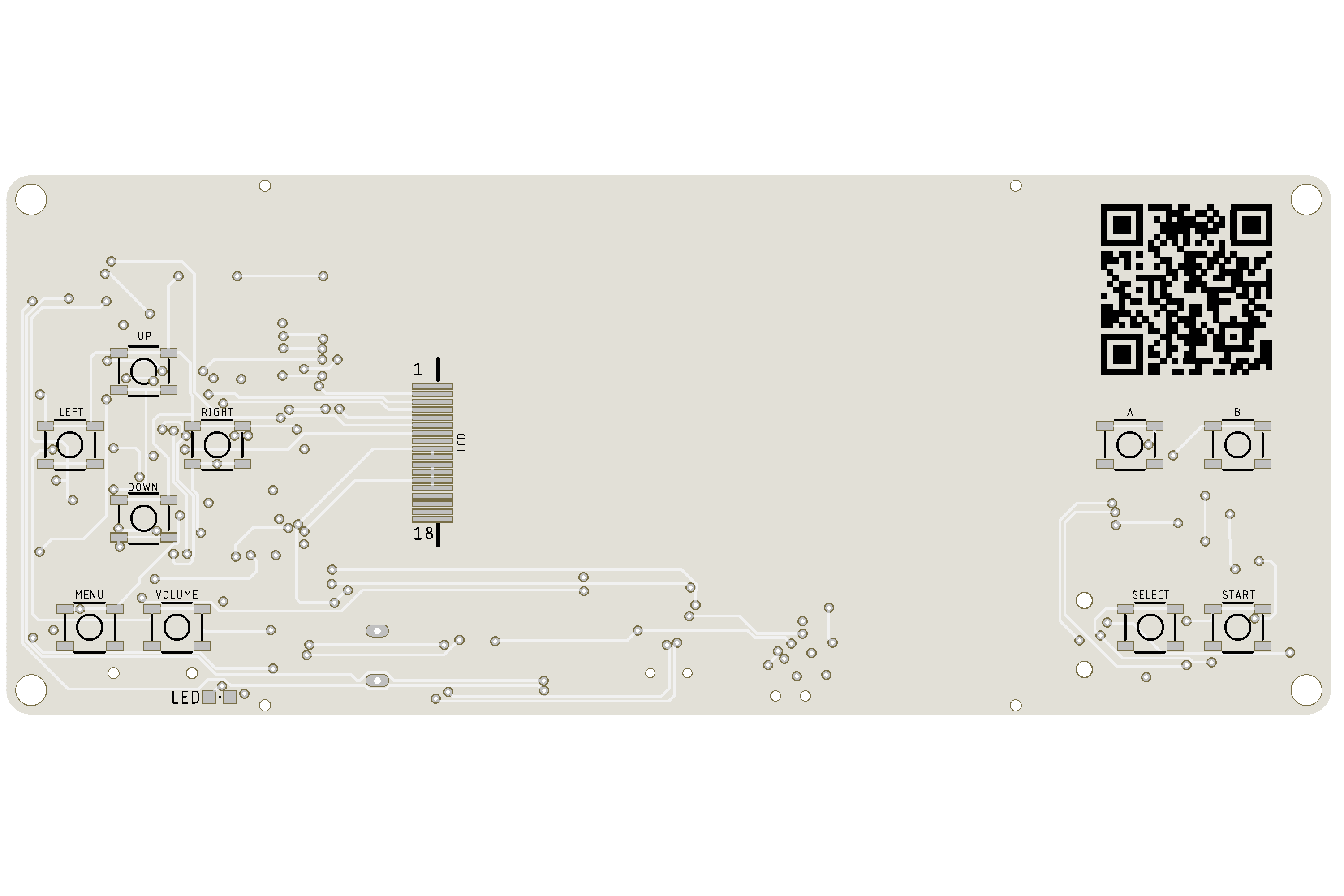
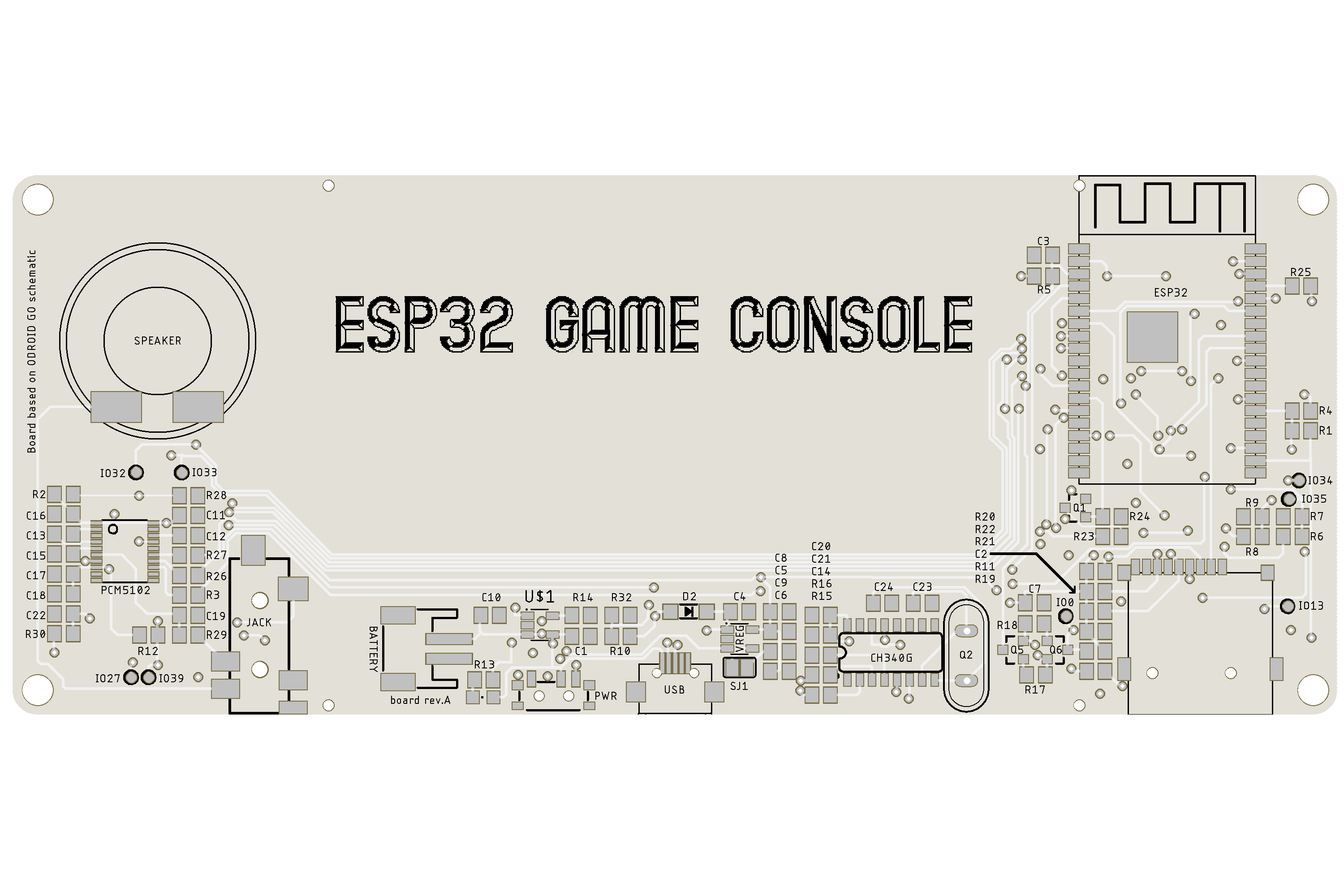
    Routed board looks like this: 

    Because I had no SMD crystal at home, I used THT one. Speaker should be connected by wires directly to board.  

    When boards arrived, I soldered one by hand with parts which I had at home. Because I did choose to use THT crystal and did not realized that I can not solder it through from bottom side, I had to solder it in standing position (can be seen on picture) so it is not sitting on the board. 

    Firstly I could not make USB converter work, but after some debugging I found out that my RX & TX  lines are swapped so that was reason why I could not make it work. To repair this, I decide to sacrifice 2 pcs of 470 ohm resistor, which are on this connection and I cross these lines with wire. After that, I could programm ESP32 chip.  

    Next problem which I encounter was with the screen. I could see that there is some image, but I had no backlight. I measured voltages on LCD and those were fine. I also checked continuity on ground plane and that was also OK. When I was trying to find out where is the problem, I sometimes made it work for a second or two with my hands, which let me to conclusion that there will be really problem with ground somewhere. I looked at schematic where should be ground and bodged it with wire and this made it work. I could not regulate brightness, but I had backlight. 

    So I had working USB converter, ESP32, SD card, screen, charging circuit and last thing on the list was sound chip (because I had to order it). I solder it on the board, fire it up and all what I heard was ticking and buzzing noise and very very low sound coming from game. This was a big problem. I spent few hours by checking the Internet if I did something wrong but schematic was right. I also used osciloscope to look if there is right signal and when I selected I2S audio in FW of OG, I saw right signals at scope and none when I choose internal sound chip in FW. After few days of trying to solve this I did find out that I made mistake with plascing of the components  and there are wrongly placed capacitors at the output signal. I desolder them and turned them by 90° and bodged them to resistors and I had working sound. At that point I was really relieved. 

    Here is final result: 

    I designed 3D printed case so anyone can print it in desired color and probably change it as well. 

    My friend Lubos Moravec made for me small intro video which you can see here:

    I was happy that I made it work and more happy when people start to comment it at YT. Someone mentioned that he would be interested in one if it has conductive buttons and not those micro switches which make quite loud clicking noise.  

    Other thing which I realized was, that not all games support this I2S sound chip and that someone could end up with no sound in game. 

    I decide to resolve this in next version.  

  • Where to begin?

    Miroslav Zuzelka07/31/2019 at 22:17 0 comments

    For those, who don´t know what Odroid Go is, here is picture:  

    You can find specification here. Basically it is small handheld device with emulator and you can play Gameboy, Nes and other game types on it. It also have support for Arduino and MicroPython, so you can make your own games in either one of those platforms. You can also buy external keyboard for it and you can use it for emulation of Commodore 64, ZX Spectrum, and MSX games.  

    When I found about this game kit I wanted to test it straight away. At first I had no luck to find some schematic, but I visited Odroid Go wiki page and I find this schematic. Now I could move forward. 

    For testing I used 2.8" Ili9341 screen from Aliexpress and connected it to the ESP32 module which I had already. I checked instructions on how to upload basic firmware and nothing happened. After some while of searching and reading through the Internet I found out that OG uses 16 MB module, which is not common on available modules. The second bad news was, that these modules are quite hard to find in small quantities and you don´t want to buy big stock of it, especially if you don´t know if your project will work. 

    Luckily I did find some eshop in Slovakia, where they sell them in small quantities and for reasonable price. I ordered few of them and because I´m mostly driven by PCB design, I started to work on first version. 

View all 5 project logs

Enjoy this project?

Share

Discussions

Martin Cejp wrote 12/05/2021 at 15:08 point

In case anybody else is wondering: the schematic and PCB Eagle project, and STL files for the housing can be found at https://github.com/dronecz/esp32-game-console

  Are you sure? yes | no

Similar Projects

Does this project spark your interest?

Become a member to follow this project and never miss any updates