-
Case and button design
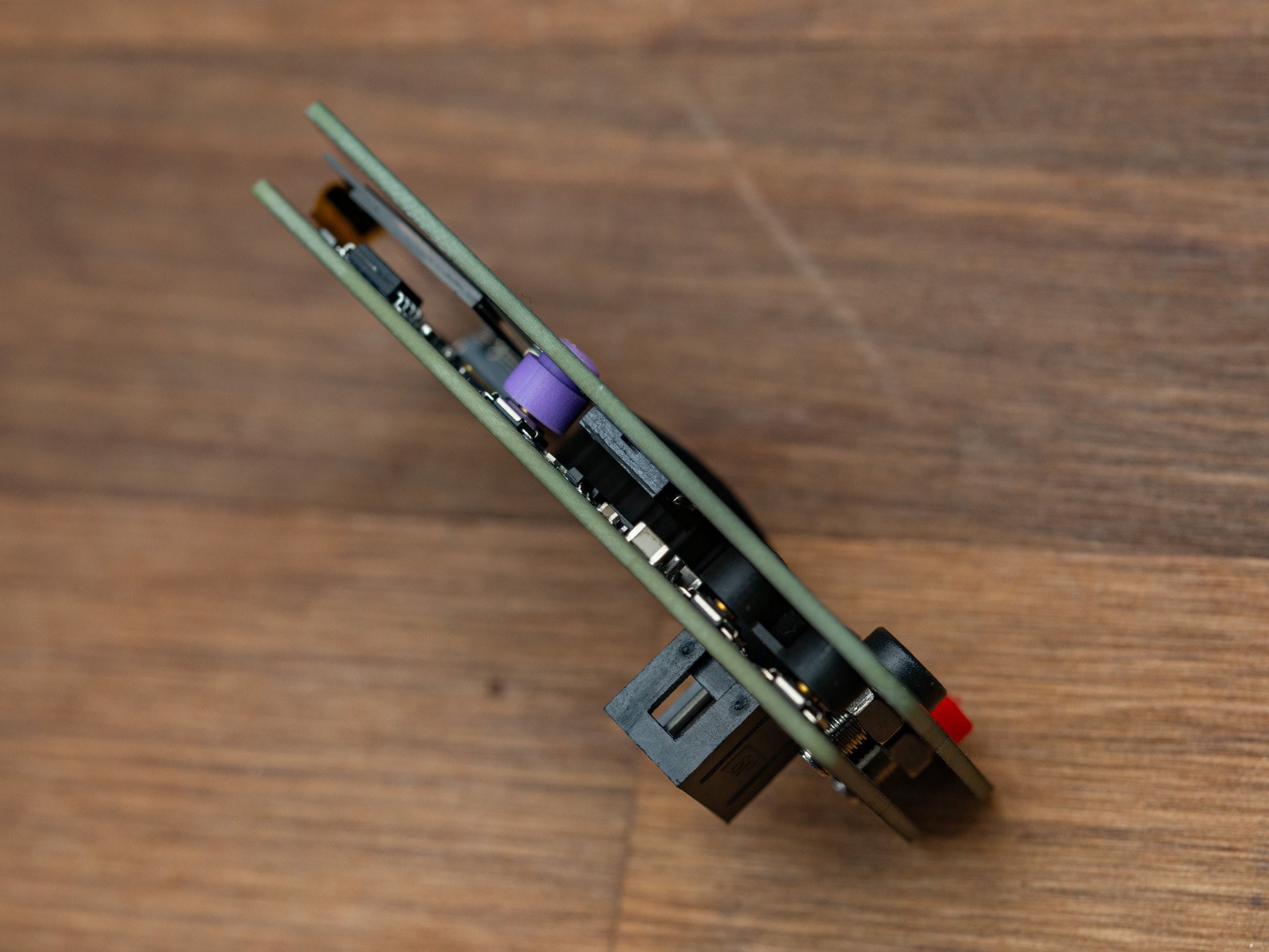
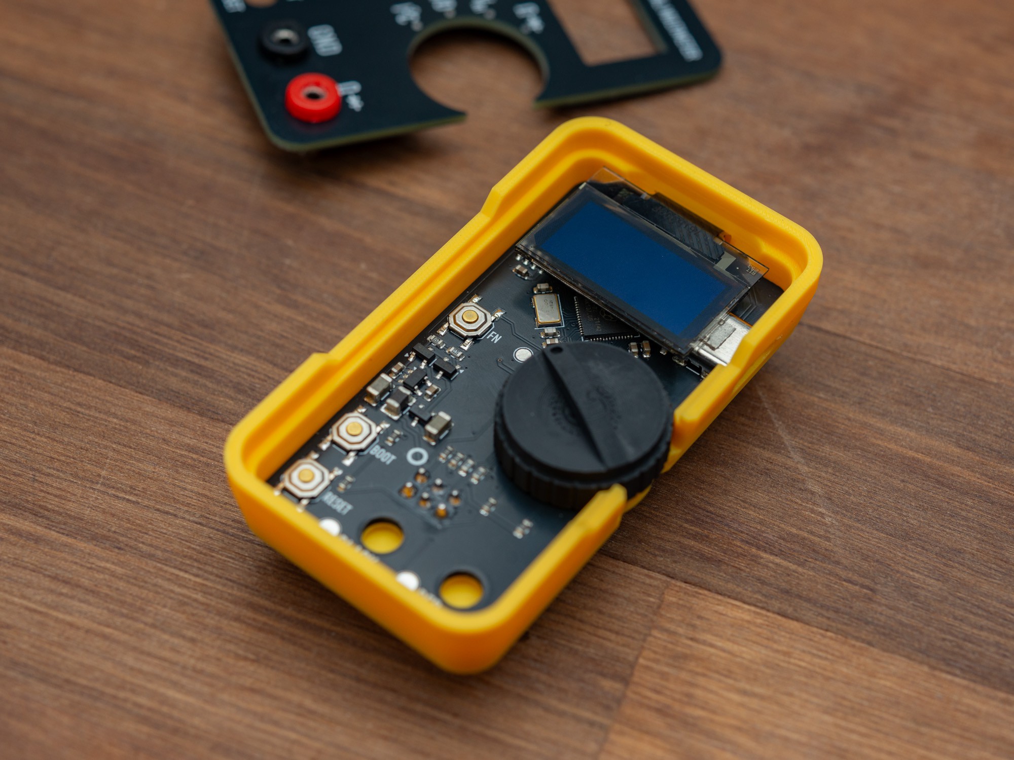
10/22/2024 at 14:08 • 0 commentsThe electronics is sandwiched between the base PCB and the front plate. In between are all the components, screen and the button caps and the main mode selection knob. Only the SAO connector sits on the back.

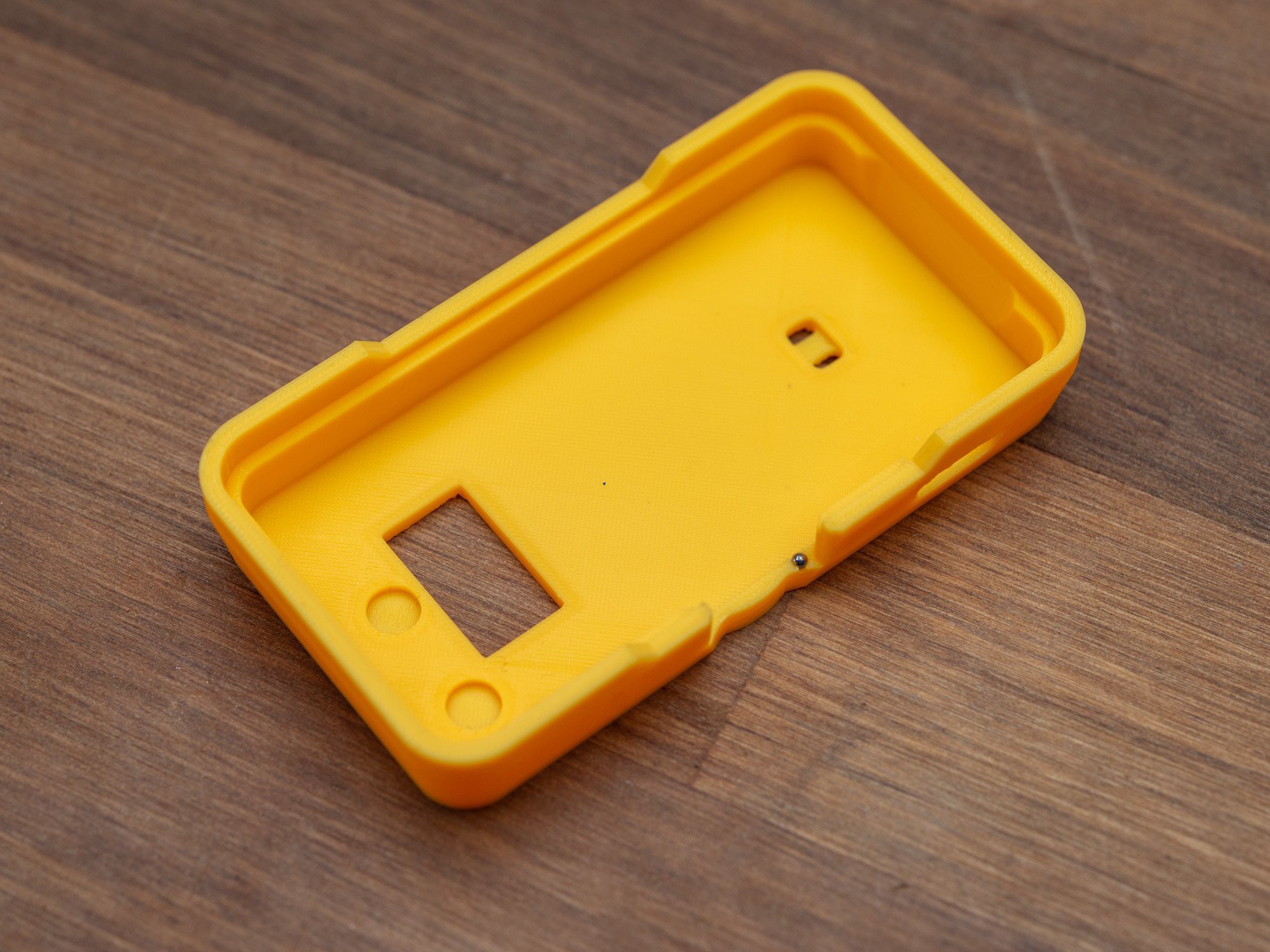
The case has a cutout for the SAO connector, small indents for the two 2mm banana sockets, and two small holes, to add a SAO leash, as an extra protection agains loosing a SAO that falls off a badge.
To have the screen sit correctly, the top of the case has been extended a little, to accommodate the flex pcb that connects it to the base board.
The distance between the boards is just enough to have the screen sit on top of the USB-C connector, about 4.9mm.

As the rotary encoder does not have stops but rotates smoothly, firm position locks are done by adding a small (Ø1.5mm) steel ball inside the case side, and adding indents for every 30° on the bottom of the knob. When the knob is squished between the two PCBs, this makes for a pretty decent feel.

The knob has small ridges on the outside, for better grib when using a thumb or similar to rotate.

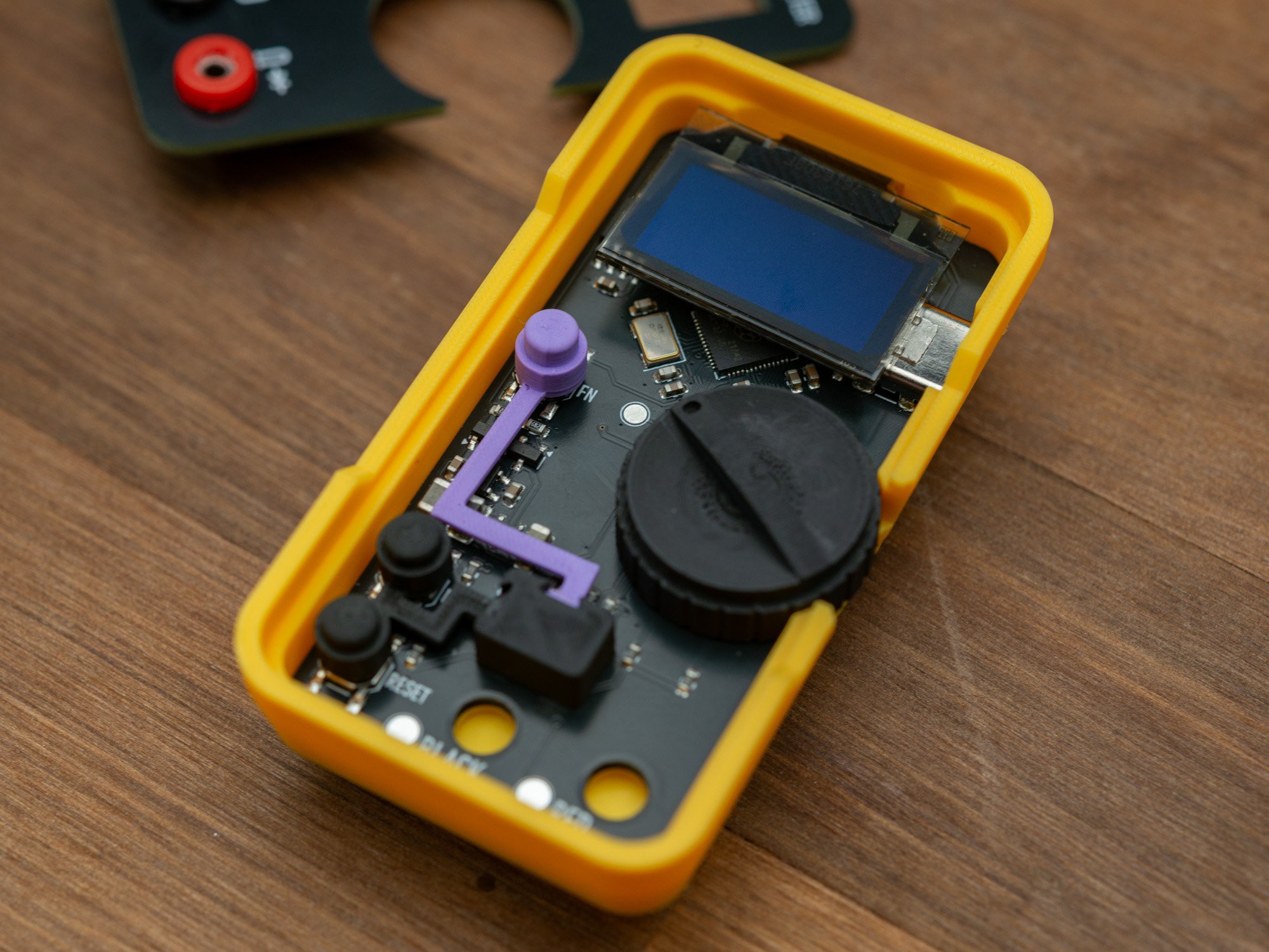
The button caps are held in place by thin printed extensions, that connect to the spacer, that sits directly above the SAO connector, preventing the bottom PCB from moving in the case, especially when inserted into a badge.

-
PCB assembly time
10/22/2024 at 13:30 • 0 commentsI generally get stencils for all projects, and use the interactive HTML BOM for assembly, combined with a camera based microscope to check orientation and proper placement.
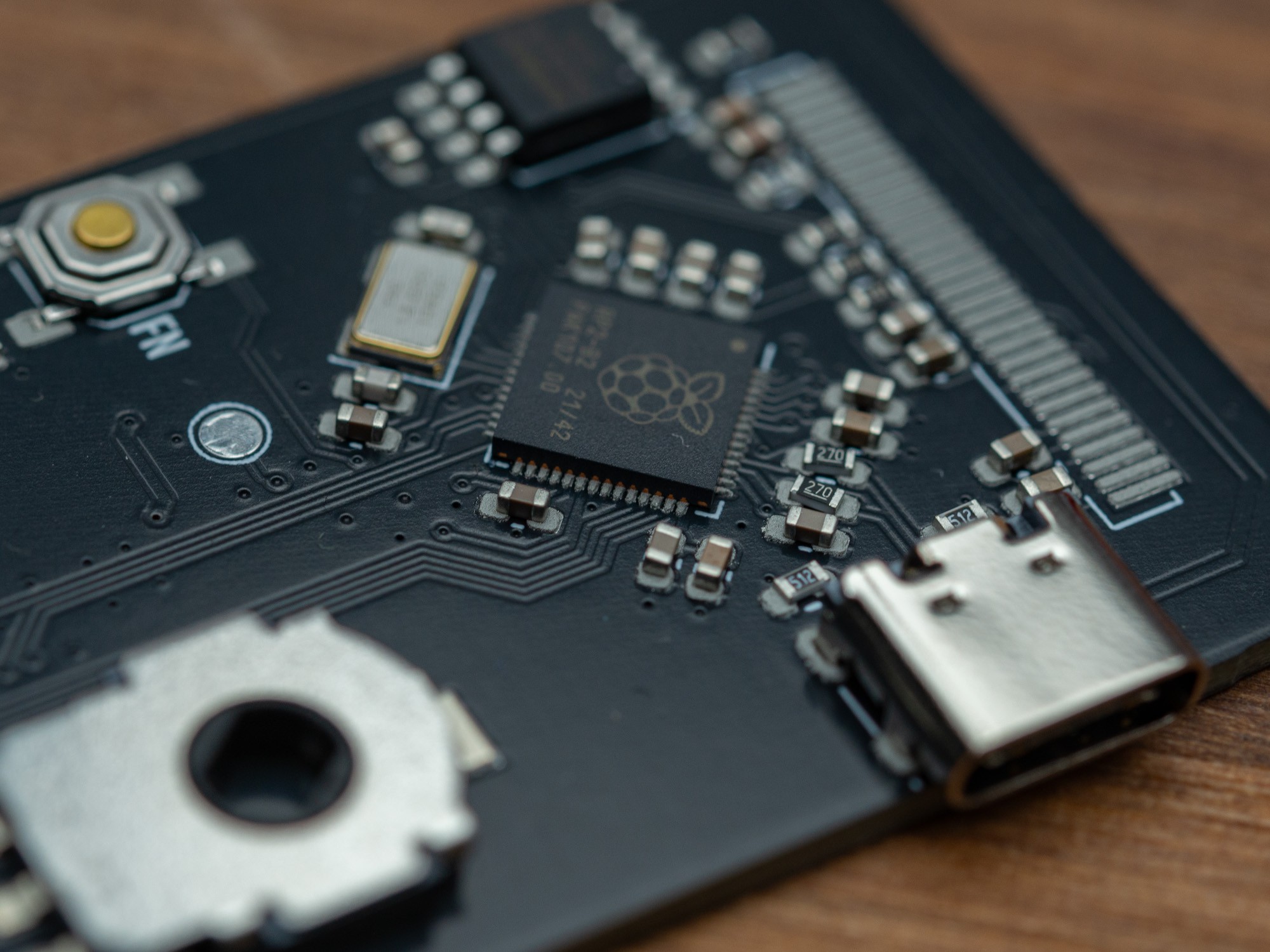
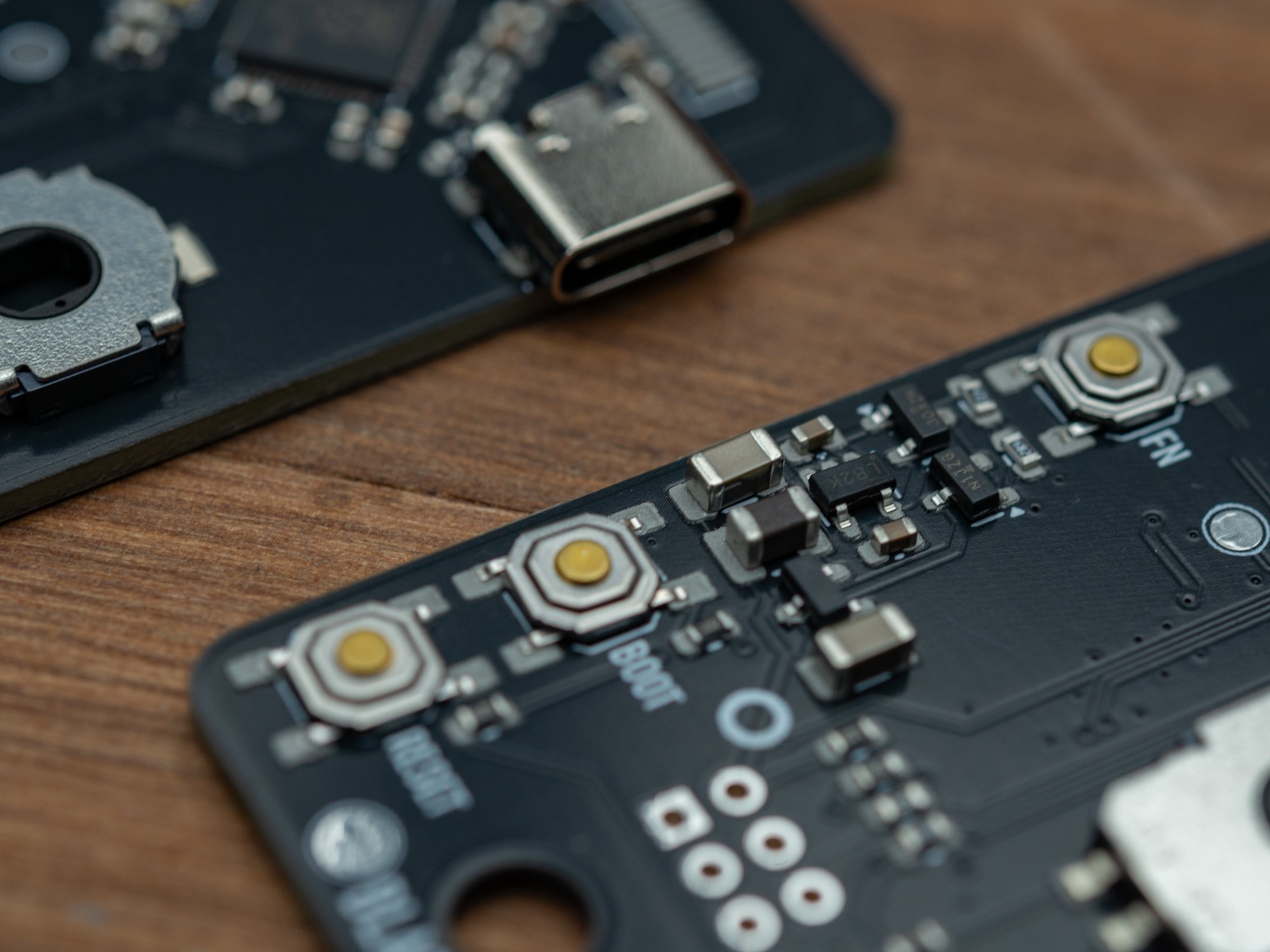
For the majority of the parts, I use a small curved tweezer (Erem), and some of the larger ones could simply be positioned by hand (rotary encoder and USB-C connector), as there are alignment holes for those.


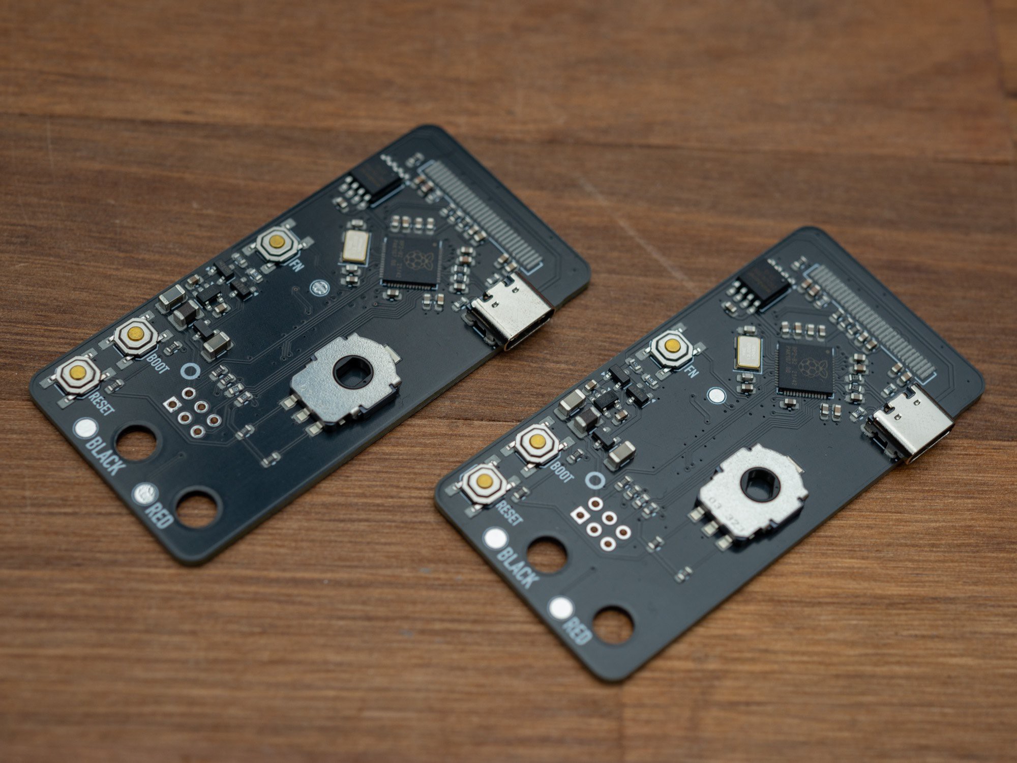
Two base boards ready for baking

I use one of these small hotplates... it a bit on the small size for this, but moving the PCB a little made sure all got soldered. Compared to the regular cooking hotplate I was using before, this is MUCH more stable with the temperature, and stays at 210°C only dips a little when I put on a new PCB (probably not the best thing to do, but I'm to impatient to wait for it to cool down)


The OLED displays are soldered on with a soldering iron and the solder that was applied during pasting. It might have been a little too much solder, as I had to redo it on one of them due to a short.

SAO Digital Multimeter
A small digital multimeter specifically for measuring SAO related stuff
 Thomas Flummer