 Yann Guidon / YGDES
The last log 137. iHP26a - post mortem explains why and how the whole thing could be rebuilt almost from scratch, so let's now start with the basic integrator-differentiator pair. It's just a 18-bit version, the modulus is added later. Moreover, each step requires an identical/equivalent representation in C (JS), VHDL, Verilog and diagram.
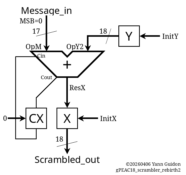
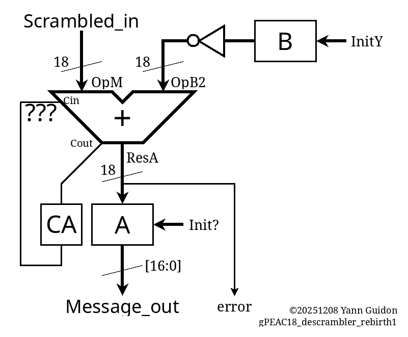
For the first step, we have a simple accumulator X, adding the (fixed) register Y to the incoming message. The decumulator does the reverse, subtracting B from the incoming message. It's not hard but keeping all representations in sync takes some efforts. (and yes, these are just registers, not accumulators, but I had to come up with a word...)
And even this simple circuit is not totally obvious. The dataflow is easy and the encoder is simple but the carry requires a lot more thinking in the receiver.
So how is the carry processed in the receiver ? what inversion is needed and where ?
CA would be reset to 0.
A subtraction needs the Cin to be set.
But I remember that there is a double-inversion somewhere and some carry was no inverted.
And I can't even get something as simple as above right on the first try in C, I must remove even more: the carry, the inversion...
................................................................
But I finally managed to get something that works in C.
#define MASK17  ((1<<17)-1)
#define MASK18  ((1<<18)-1)
#define MODULUS (258114)
#define ADJUST  (262144-MODULUS)
#define INIT_X   (56247) // "01101101110110111"
#define INIT_Y  (2*(111981)) // "11011010101101101"  2× to trigger carry

// Scrambler
int Message_in, OpM, OpY2, ResX, X, Y,
    CX, CXin, CXout, Scrambled_out;

void init_scrambler() {
  X=INIT_X;  // does not matter yet
  Y=INIT_Y;
  CX=0;
}

void cycle_scrambler() {
  OpM = Message_in;
  OpY2 = Y;
  CXin = CX;
  ResX = OpM + OpY2 + CXin;
  X = ResX & MASK18;
  CX = ResX >> 18;
  Scrambled_out = X;
}

// Decrambler
int Scrambled_in, OpM2, OpB2, B, A, ResA,
    CA, CAin, CAout, Message_out, error;

void init_descrambler() {
  A=-1;
  B=INIT_Y;
  CA=1;
}

void cycle_descrambler() {
  OpM2 = Scrambled_in;
  OpB2 = (~B) & MASK18;
  CAin = CA;
  ResA = OpM2 + OpB2 + CAin;
  A  = ResA & MASK18;
  CA = ResA >> 18;
  Message_out = ResA & MASK17;
  error = (ResA >> 17 ) & 1;
}
I modified INIT_Y to force the carry condition, don't worry.
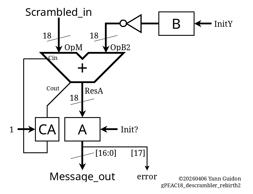
CA and CX are inverted from each other, but it comes from the computation, no need of explicit inverstion. Only initialise them properly: CX=0, CA=1. It's simple yet very not obvious...
This inversion situation needs proper modelling and explanation.
- CX and CA are complementary because the sum of INIT_Y and 1 + ~INIT_Y gives 1<<18.
- CX goes 1 when Message_in >= (1 + ~INIT_Y)
- conversely CA goes 1 when Scrambled_in >= INIT_Y (or something ... I'm still confused)
- Both addends make the whole word go +(1<<18) so there IS a carry in any case, either in CA or CX.
- In the end, CAout is fed directly into CAin. So we can remove the question marks.
The code is in rb1.c, it generates these test vectors:
[     42,  224004],
[  24455,  248417],
[  48868,   10686],
[  73281,   35100],
[  97694,   59513],
[ 122107,   83926],
[  15448,  239411],
[  39861,    1679],
[  64274,   26093],
[  88687,   50506],
[ 113100,   74919],
[   6441,  230404],
[  30854,  254816],
[  55267,   17085],
[  79680,   41499],
[ 104093,   65912],
[ 128506,   90325],
[  21847,  245810],
[  46260,    8078],
[  70673,   32492],
[  95086,   56905],
[ 119499,   81318],
[  12840,  236803],
[  37253,  261215],
[  61666,   23484],
[  86079,   47898],
[ 110492,   72311],
[   3833,  227796],
[  28246,  252208],
[  52659,   14477],
Now, the VHDL and mapped Verilog versions should be easy to deduce.
.
Well, VHDL certainly was (almost) a walk in the park. Encoding goes like this:
  -- encoder
  signal Message_in    : std_ulogic_vector(16 downto 0);
  signal Scrambled_out : std_ulogic_vector(17 downto 0);
  signal CX, CY : std_ulogic;
  signal  X,  Y : std_ulogic_vector(17 downto 0);
  signal OpM, OpY2: std_ulogic_vector(17 downto 0);
  signal CXin,  CYin, CXout, CYout : std_ulogic;
  signal ResX, ResY : unsigned(19 downto 0);

    procedure init_scrambler is
    begin
      X <= INIT_X;  -- does not matter yet
      Y <= INIT_Y;
      CX<= '0';
      wait for 1 ns;
    end procedure;

    procedure cycle_scrambler is
    begin
      wait for 1 ns;

      OpM <= '0' & Message_in; -- pad MSB
      OpY2 <= Y;
      CXin <= CX;
      wait for 1 ns;

      ResX <= unsigned('0' & OpM  & '1' )
            + unsigned('0' & OpY2 & CXin);
      wait for 1 ns;

      CXout <= std_ulogic(ResX(19));
      X <= std_ulogic_vector(ResX(18 downto 1));
      wait for 1 ns;

      CX <= CXout;
      Scrambled_out <= X;
      wait for 1 ns;
    end procedure;
I replaced variables with signals so gtkwave could see them. All the "wait for"s bloat the code but it does not matter.
Decoding is similar.
  -- decoder
  signal Scrambled_in : std_ulogic_vector(17 downto 0);
  signal Message_out  : std_ulogic_vector(16 downto 0);
  signal CA, CB,  CAin,  CBin, CAout, CBout, error : std_ulogic;
  signal  A,  B : std_ulogic_vector(17 downto 0);
  signal OpM2, OpB2: std_ulogic_vector(17 downto 0);
  signal ResA, ResB : unsigned(19 downto 0);

    procedure init_descrambler is
    begin
      --A <= INIT_X;  -- does not matter yet
      B <= INIT_Y;
      CA<= '1';
    end procedure;

    procedure cycle_descrambler is
    begin
      wait for 1 ns;

      OpM2 <= Scrambled_in;
      OpB2 <= not B;
      CAin <= CA;
      wait for 1 ns;

      ResA <= unsigned('0' & OpM2 & '1' )
            + unsigned('0' & OpB2 & CAin);
      wait for 1 ns;

      A <= std_ulogic_vector(ResA(18 downto 1));
      CAout <= std_ulogic(ResA(19));
      wait for 1 ns;

      CA <= CAout;
      Message_out <= A(16 downto 0);
      error <= A(17);
      wait for 1 ns;
    end procedure;
It matches the C code and it's all in rb1.vhdl.
.
.
For the Verilog version.... rain is pouring on the proverbial park.
- first I had to come up with a translation layer to insulate the PDK from pesky variations between the iHP G2 and CMOS5L version. That has given https://github.com/YannGuidon/IHP_SG13_cells after a lot of wrangling with sed.
- but then, I need a functioning place to put the files, and I want to reuse https://github.com/ygdes/miniMAC_5Lwithout touching it. This is already a fork and github does not let me fork it further... So I guess the only remaining solution is to restart from scratch. So I must clone everything locally, treat all the files and then reupload them in a new instance of the original SG13G2 template... I hate git.
But in the end, coding has resumed.
.
Already I can find a few errors, such as
- B initialised to the wrong value,
- the CA bit reset instead of set.
- INIT_X And INIT_Y being ... wroooong.... (dffen_rs_x18 was bork)
Add to this the timing bug of the output multiplexer and you understand why the first tape out had no chance of working as intended.
But finally, the verilog version of the encoder is conform, at last !
     0.00ns INFO     cocotb.tb          Reset
 50000.00ns INFO     cocotb.tb          Starting bypass Mode
2120000.00ns INFO     cocotb.tb         RB1 Scrambling Mode
 - in: 42   found: 224004   expected: 224004
 - in: 24455   found: 248417   expected: 248417
 - in: 48868   found: 10686   expected: 10686
 - in: 73281   found: 35100   expected: 35100
 - in: 97694   found: 59513   expected: 59513
 - in: 122107   found: 83926   expected: 83926
 - in: 15448   found: 239411   expected: 239411
 - in: 39861   found: 1679   expected: 1679
 - in: 64274   found: 26093   expected: 26093
 - in: 88687   found: 50506   expected: 50506
 - in: 113100   found: 74919   expected: 74919
 - in: 6441   found: 230404   expected: 230404
...
https://github.com/ygdes/miniMAC_IHP/actions/runs/24052860568/job/70152404603
Then test the decoder and the loopback...
and it passes all tests and synthesis: https://github.com/ygdes/miniMAC_IHP/actions/runs/24056359563 (including the Hammer here)
.
Discussions
Become a Hackaday.io Member
Create an account to leave a comment. Already have an account? Log In.