 Yann Guidon / YGDES
20260326: #YGMII spin off
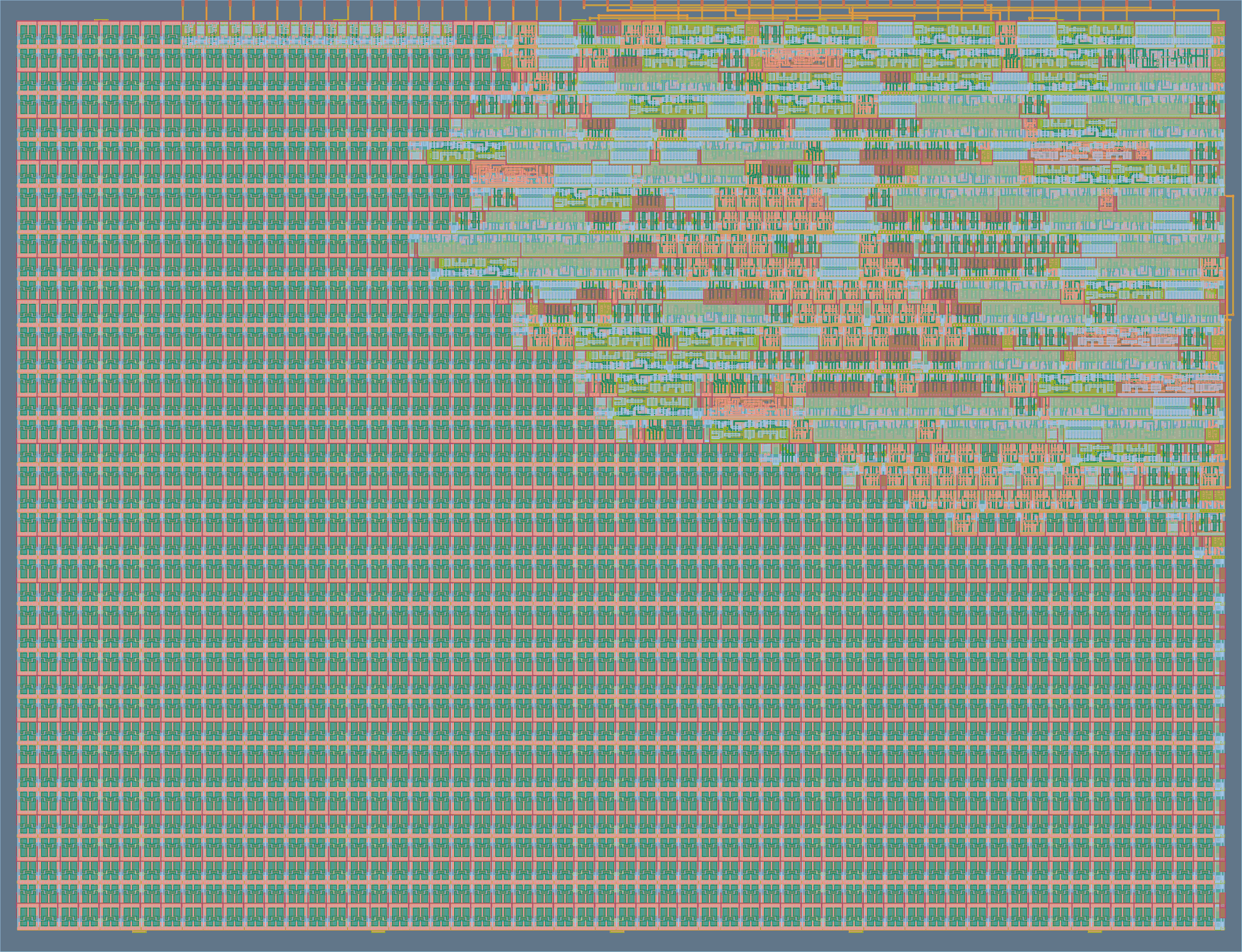
20260225: ASIC with Tiny Tapeout
20251113: Architecture update
20250525: spinning #miniPHY off.
.
miniMAC is an extension and application of #PEAC Pisano with End-Around Carry algorithm because the PEAC algorithm replaces the checksum, the scrambler and the 4b/5b table usually employed by 100Base-TX, see
166. Line encoding with PEAC : OK
167. Line encoding with PEAC: it's alive
168. PEACLS error detection (and correction?)
169. TODO: scan
Application is for embedded/custom data transfers over RJ45/Cat5 UTP/STP where the whole TCP/IP stack is not required and a simple FPGA/microcontroller are more than enough.
.
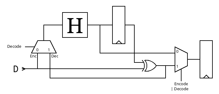
A PAM3-based + gPEAC18 version is currently in development. The GrayPar layer is replaced by a NRZI+Hammer convolutional error amplifier that detects more errors, faster, optimising the descrambler's work and reducing the FIFOs' depths. There is no error correction but detection is solid and fast, allowing almost immediate retransmit of the most recent data, thus optimising actual bandwidth in difficult environments (like industrial, automotive...).
-o-O-0-O-o-
Logs:
1. Let's start.
2. Tinkering with CircuitJS
3. AGC
4. Serial vs Parallel
5. Sender-side droop/wander prevention with MLT-3
6. Double parity
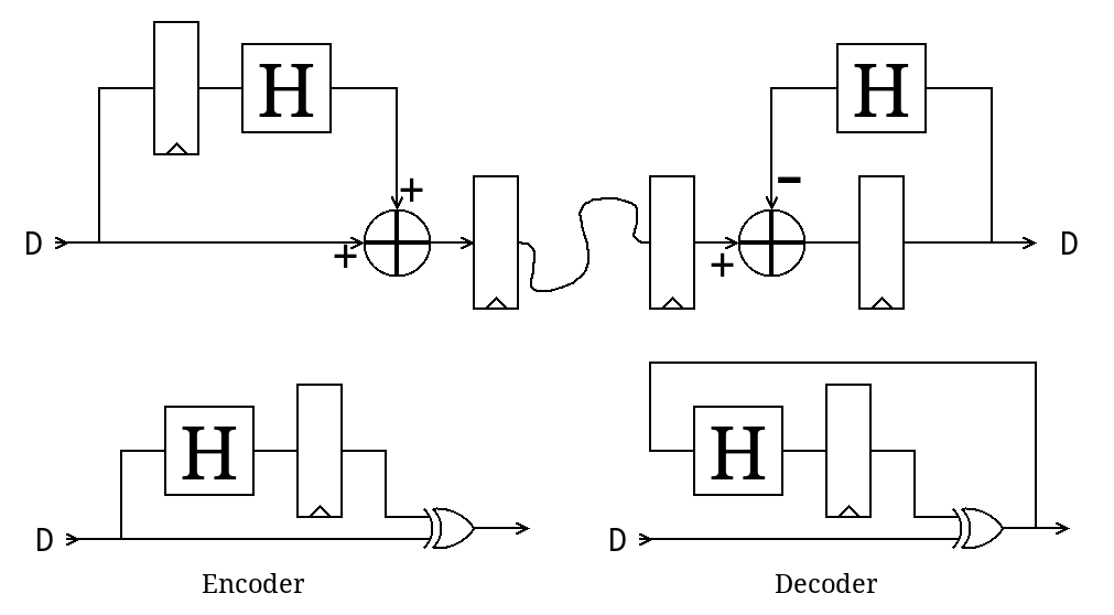
7. Flipping
8. a Quasi-Popcount
9. gPEAC again
10. Popcount
11. the bi-flipper topology
12. Ternary encoding
13. The whole flip+parity extension stage
14. Should 4 be flipped...
15. Popcount (better)
16. Run Length Limitation, reduced
17. Making it work
18. Protect the flip bits
19. Error detection
20. Modulation, simplified for now - NRZi
21. Architecture
22. Ternarity and more
23. SU(3)
24. mod3
25. mod3bis
26. Bidir PEAC+ParPop
27. Two lanes
28. Bidir ParPop : OK
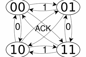
29. Protocol
30. DPLL-1
31. I need a name.
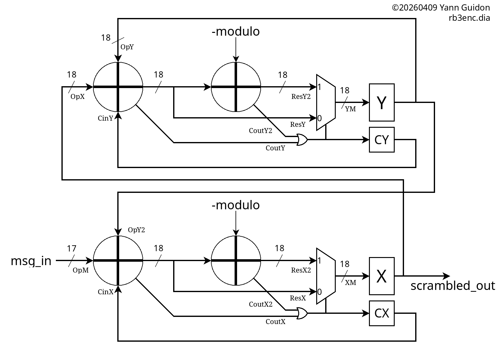
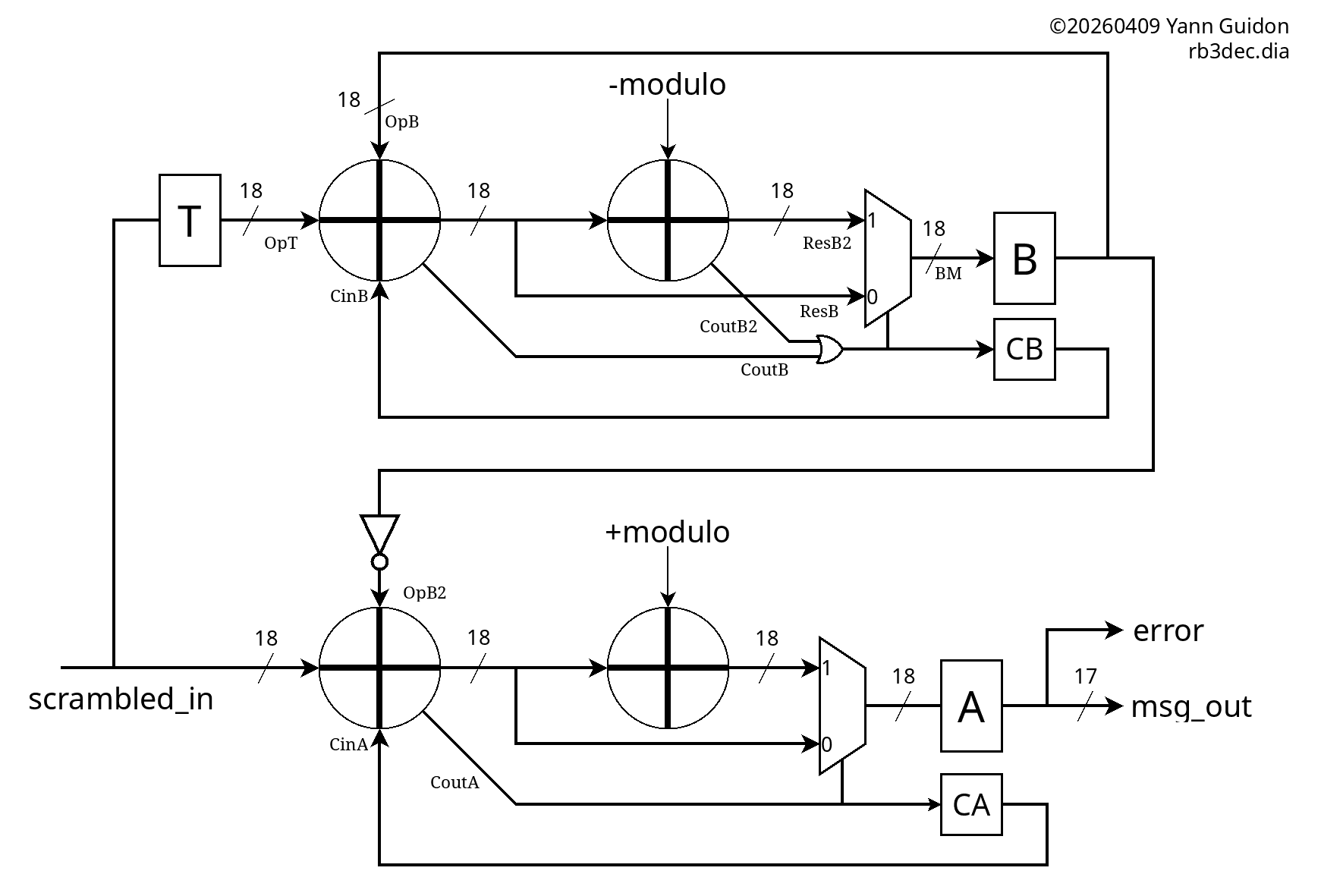
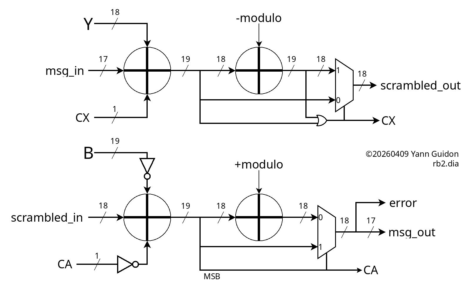
32. Reversible PEAC scrambler
33. TMDS
34. PEAC treillis
35. PEAC Reversibility achieved
36. Bidirectional pipeline
37. Dual-lane version: easy
38. DPLL-2
39. Line compensations
40. Maximum avalanche time
41. Transition minimisation
42. The "same" symbol
43. PAM3 and the bi-Trits
44. The ParRot
45. Constellation 2
46. The spreader
47. Gray parity
48. One more bit...
49. Larger words
50. The new parity circuit
51. Permutations
52. Permutations 2
53. The last parity
54. Control Word Sequence
55. Rebuild
56. Detection latency and buffer depth
57. Burst errors
58. Protocol revision
59. MAC & PHYs
60. The error model of PEAC scramblers
61. Shared PEAC
62. Sub-protocol: QSDE
63. miniPHY
64. New pipeline
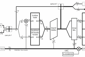
65. GrayPar17
66. ADD3-EAC
67. Move the NOTs
68. Fewer burst errors
69. spurious errors
70. Stats with GrayPar17 and PEAC16x2
71. Not XOR, not ADD, then what ?
72. Add, Sub and errors
73. Multi-bit errors
74. Galois fields ?
75. Better markers
76. Better stats
77. buffer prefix
78. gPEAC18
79. A matter of channels...
80. Architecture (summer edition)
81. Unit swap
82. Unit swap (2)
83. Extended control words
84. GrayPar18
85. Article
86. A variable-strength adaptive parity
87. New pipeline
88. New pipeline (2)
89. GrayPar18: 5+5+5+3
90. ParGray: it's reversible!
91. New modulo.
92. Nested Gray Parity Loops
93. New new modulo.
94. Error detection: how it fits in the protocol
95. Meanwhile: Koopman
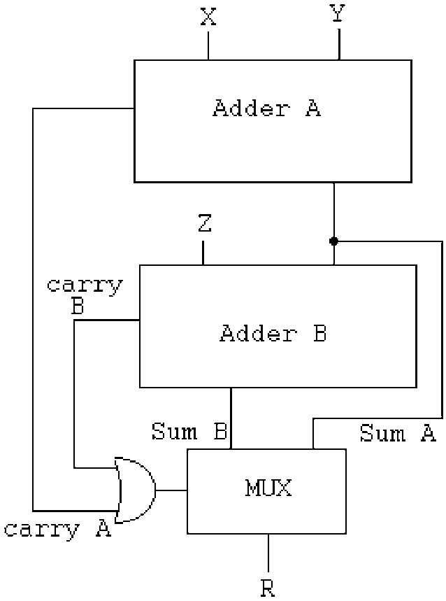
96. Modular adder
97. Coding space
98. Architecture update
99. Parallel bus
100. C/D in the middle
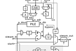
101. gPEAC: the circuit
102. gPEAC circuit correction
103. New new new modulo.
104. Orbit length invariance
105. gPEAC: the (other) circuuit
106. gPEAC18 descrambler (la suite)
107. Bus Inversion
108. Error correction
109. Scrambler (clearer)
110. Scrambler and descrambler: almost ready
111. Scrambler and descrambler: VHDL
112. gPEAC stress test
113. More gPEAC18 results
114. Even more gPEAC18 results
115. PEAC flaw
116. NRZ FTW
117. Checking more assumptions
118. Max Hamming
119. A reversible mixing primitive
120. Hamming distance maximiser
121. MaxHam gen2
122. Brute-forcing the permutations
123. Brute-forcing in C
124. Proof, pudding.
125. Lemon and lemonade
126. Hammer = Hamming Maximiser
127. Looping the Hammer
128. Success
129. No more gPEAC ?
130. Gaming the error detection
131. Article + on hold
132....


https://arstechnica.com/gadgets/2023/06/speed-matters-how-ethernet-went-from-3mbps-to-100gbps-and-beyond