Yann Guidon / YGDES
-
Re-birth (3) : the Y/B paths
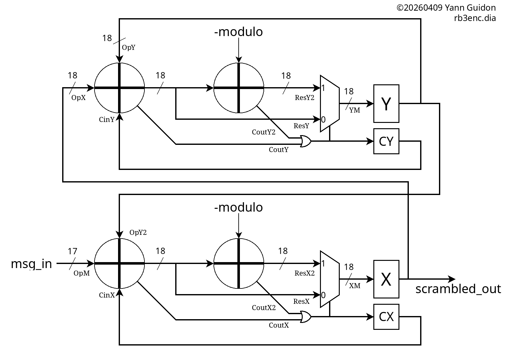
04/09/2026 at 20:11 • 0 commentsIt's time to restore the Y path. For the encoder, it's mostly a copy-paste-rename of the X path, then the results are interconnected.
![]()
(and seeing this, knowing what I now know, I realise it could become a mean TurboCode system if the Y output is interleaved with the X output)
Copy-paste is easy, just as it is easy to mess up. Beware of the excess of confidence.
![]()
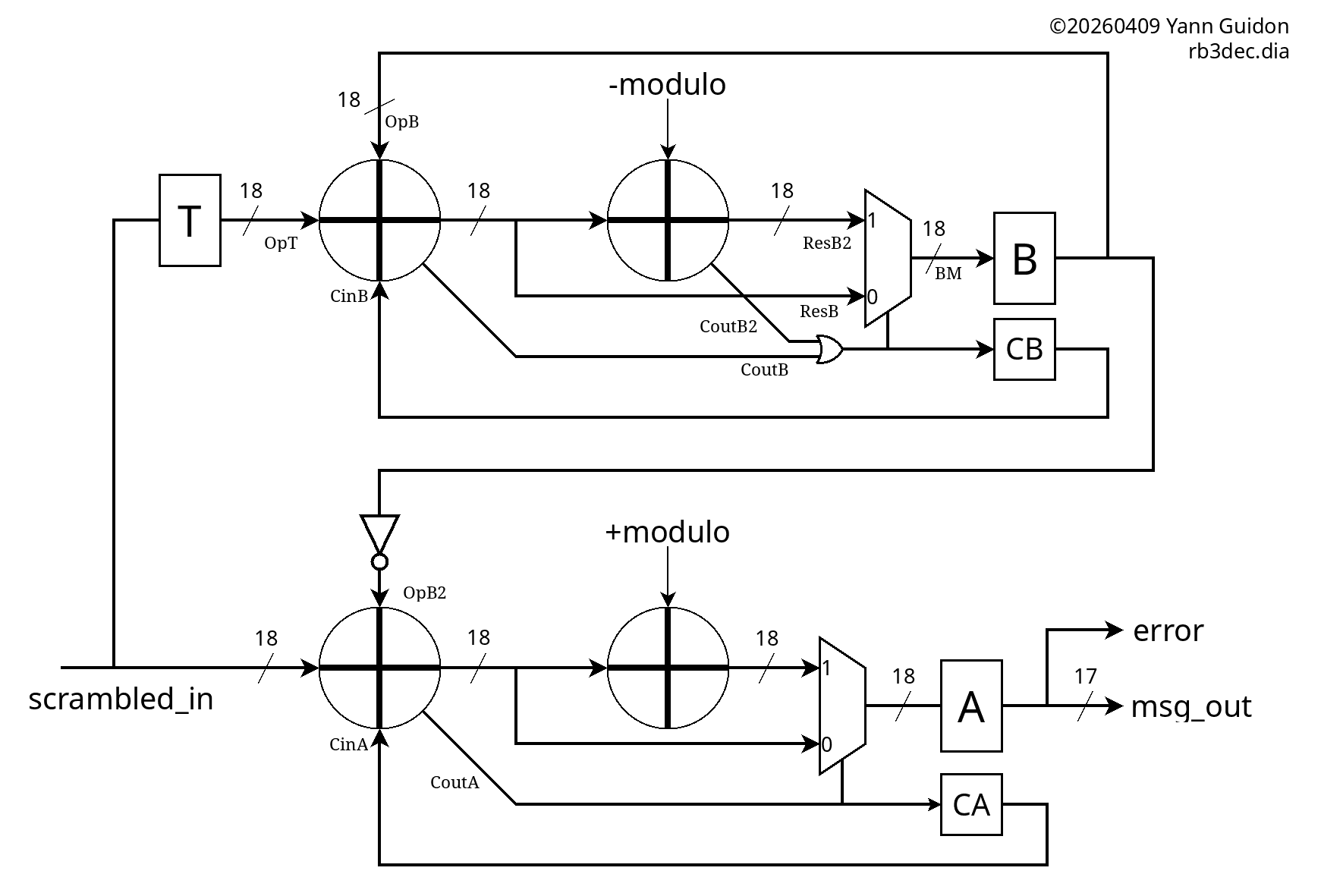
Just as with the encoder, the B path is a copy-paste of the Y path, but the source is not the decoded output, rather it's a delayed version of the input.
The A register has no feedback, it's just a temporal fence, and the T register is simply a delay (that gets initialised with INIT_X)
............................
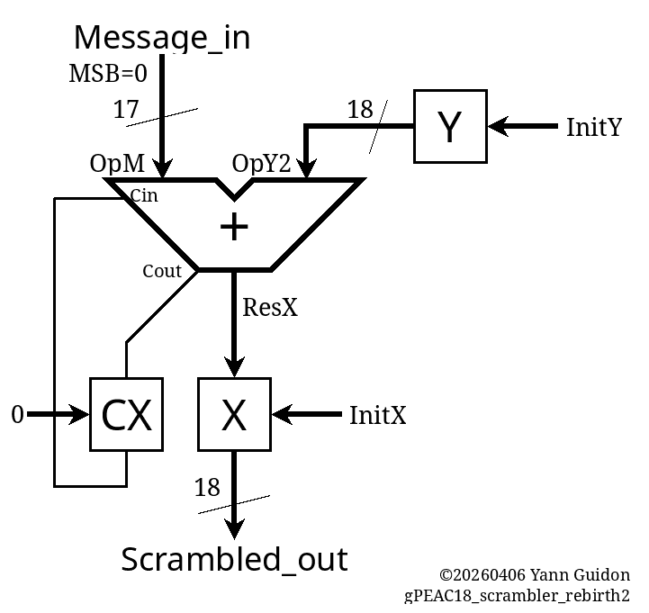
The copy-paste-rename took longer than it should, as usual, but the result matched the theory immediately. The encoder shows its duplication:
// Scrambler
int Message_in, OpM, OpY2, ResX, X, Y, CX,
    CXin, CXout, Scrambled_out, ResX2,
    OpX, OpY, CYin, CoutY, CoutY2, ResY, ResY2, CY;

void init_scrambler() {
  X=INIT_X;
  Y=INIT_Y;
  CX=0;
  CY=0;
}

void cycle_scrambler() {
  OpM = Message_in;
  OpY2 = Y;
  CXin = CX;
  ResX = OpM + OpY2 + CXin;

  OpX = X;
  OpY = Y;
  CYin = CY;
  ResY = OpX + OpY + CYin;

  X = ResX & MASK18;
  ResX2 = ResX + ADJUST;
  CX = (ResX | ResX2) >> 18;
  if (CX)
    X = ResX2 & MASK18;

  Y = ResY & MASK18;
  ResY2 = ResY + ADJUST;
  CY = (ResY | ResY2) >> 18;
  if (CY)
    Y = ResY2 & MASK18;

  Scrambled_out = X;
}
The decoder is a copy-paste-rename of the B path and the asymetry is obvious:
// Decrambler
int Scrambled_in, OpM2, OpB2, B, A, ResA, CA,
    CAin, CAout, Message_out, error, ResA2,
    T, OpT, CBin, OpB, ResB, ResB2, CoutB, CoutB2, CB;

void init_descrambler() {
  A=-1;
  B=INIT_Y;
  T=INIT_X;
  CA=1;
  CB=0;
}

void cycle_descrambler() {
  OpM2 = Scrambled_in;
  OpB2 = (~B)&MASK18;
  CAin = CA;
  ResA = OpM2 + CAin + OpB2;

  OpB = B;
  OpT = T;
  CBin = CB;
  ResB = OpB + OpT + CBin;
  T = Scrambled_in;

  A  = ResA & MASK18;
  ResA2 = A + MODULUS;
  CA = (ResA >> 18) & 1;
  if (!CA)
    A = ResA2 & MASK18;

  B = ResB & MASK18;
  ResB2 = ResB + ADJUST;
  CB = (ResB | ResB2) >> 18;
  if (CB)
    B = ResB2 & MASK18;

  Message_out = A & MASK17;
  error = (A >> 17 ) & 1;
}
..................
VHDL passes without effort but the tests don't match the C vectors. The INIT_X and INIT_Y are different so I have redefined them
#define INIT_X  (187319) // "101101101110110111"
#define INIT_Y  (111981) // "011011010101101101"
...
generic (
  INIT_X : std_ulogic_vector(17 downto 0) := "101101101110110111"; -- 187319
  INIT_Y : std_ulogic_vector(17 downto 0) := "011011010101101101"; -- 111981
  ADJUST : std_ulogic_vector(17 downto 0) := "000000111110111110"; -- 4030
  MODULO : std_ulogic_vector(17 downto 0) := "111111000001000010"  -- 258114
);
And now the vectors are good !
[   1234,  113215],
[  38650,   79836],
[  76066,  230468],
[ 113482,   89606],
[  19826,  226419],
[  57242,   95327],
[  94658,  101049],
[   1002,  102721],
[  38418,  241186],
[  75834,  123209],
[ 113250,  143698],
[  19594,  173252],
[  57010,   96252],
[  94426,   48807],
[    770,   51404],
[  38186,  137627],
[  75602,  226447],
[ 113018,  143376],
[  19362,   18054],
[  56778,  198847],
[  94194,  254317],
[    538,  101394],
[  37954,  135014],
[  75370,   15711],
[ 112786,  188142],
[  19130,  110197],
[  56546,   77641],
[  93962,  225255],
[    306,  209240],
[  37722,  213797],
[  75138,  202340],
[ 112554,  195440],
[  18898,   46011],
[  56314,   20754],
[  93730,  104182],
[     74,   31280],
[  37490,  172878],
[  74906,  241574],
[ 112322,  193754],
[  18666,   83559],
[  56082,   56616],
[  93498,  177592],
[ 130914,   13510],
[  37258,   97447],
[  74674,  148373],
[ 112090,   25122],
[  18434,   79840],
[  55850,  142378],
[  93266,    1520],
[ 130682,  181315],
[  37026,   89179],
[  74442,   49796],
[ 111858,  176392],
[  18202,  132532],
[  55618,   88226],
[  93034,      61],
[ 130450,  125704],
[  36794,   32109],
[  74210,  195229],
[ 111626,    6640],
[  17970,  108214],
[  55386,  152270],
[  92802,   39786],
[ 130218,  229473],
[  36562,  175603],
[  73978,  184378],
[ 111394,  139284],
[  17738,  230007],
[  55154,  148593],
[  92570,  157903],
[ 129986,   85799],
[  36330,  150047],
[  73746,   15148],
[ 111162,  202612],
[  17506,  124104],
[  54922,  106018],
[  92338,    9425],
[ 129754,  152860],
[  36098,   68629],
[  73514,     791],
[ 110930,  106837],
[  17274,   13972],
[  54690,  158225],
[  92106,  209613],
[ 129522,  147140],
[  35866,    4984],
[  73282,  189541],
[ 110698,  231941],
[  17042,   69712],
[  54458,   80956],
[  91874,  188085],
[ 129290,   48343],
[  35634,  142773],
[  73050,  228532],
[ 110466,  150607],
[  16810,   27370],
[  54226,  215394],
[  91642,   22066],
[ 129058,   16763],
[  35402,  203288]
.
And finally: Verilog.
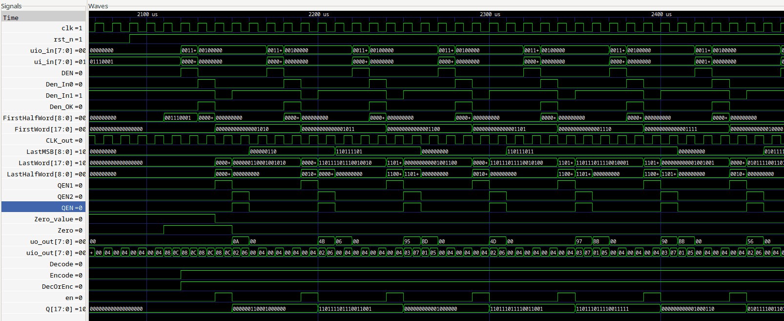
And it's a weird bug:
8240000.00ns INFO     cocotb.tb                          RB3 Descrambling Mode
 - in: 113215   found: 1234   expected: 1234
 - in: 79836   found: 79834   expected: 38650
 - in: 230468   found: 230467   expected: 76066
 - in: 89606   found: 89605   expected: 113482
 - in: 226419   found: 226418   expected: 19826
so the output is input +1 or +2.
...
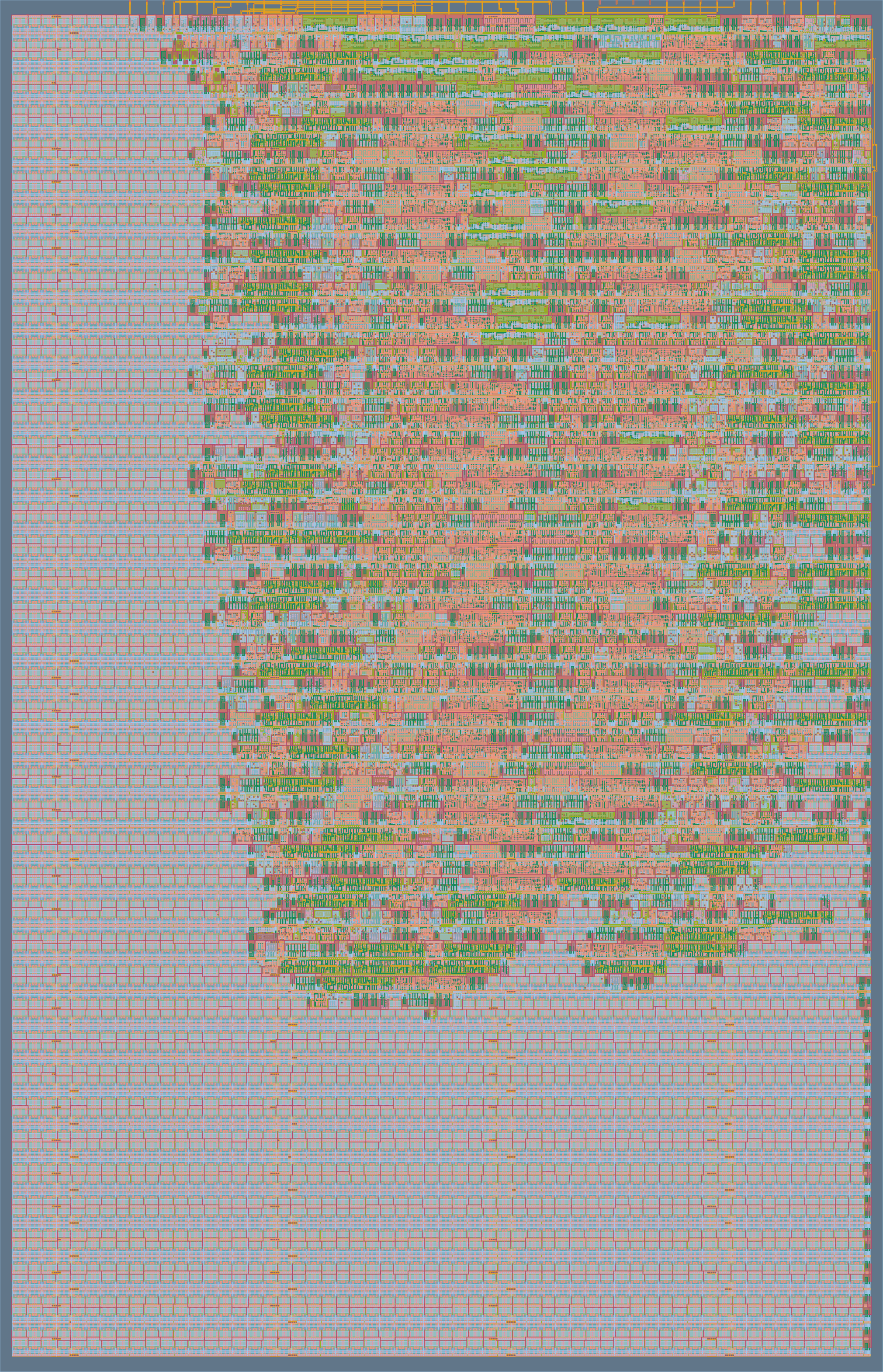
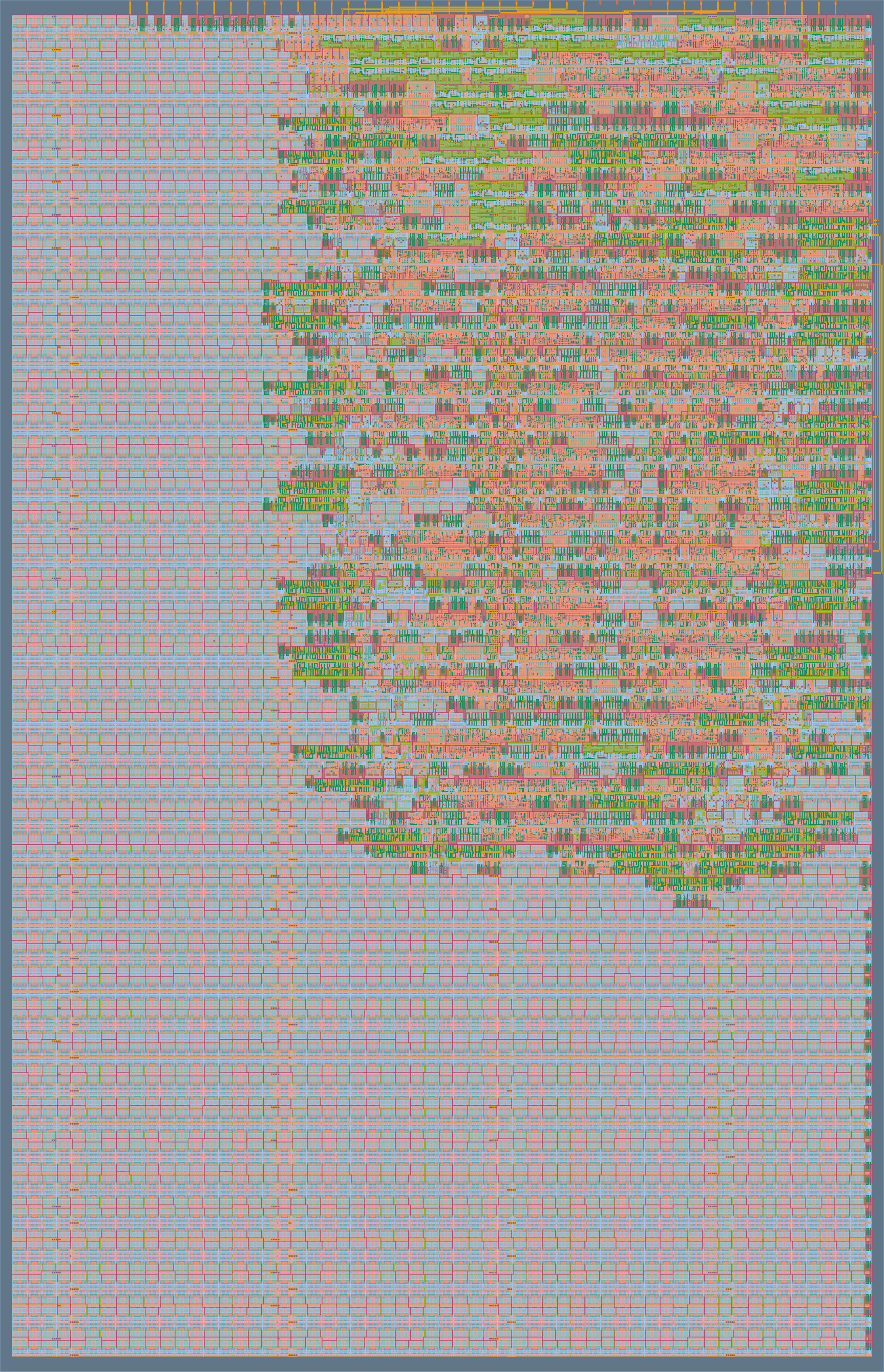
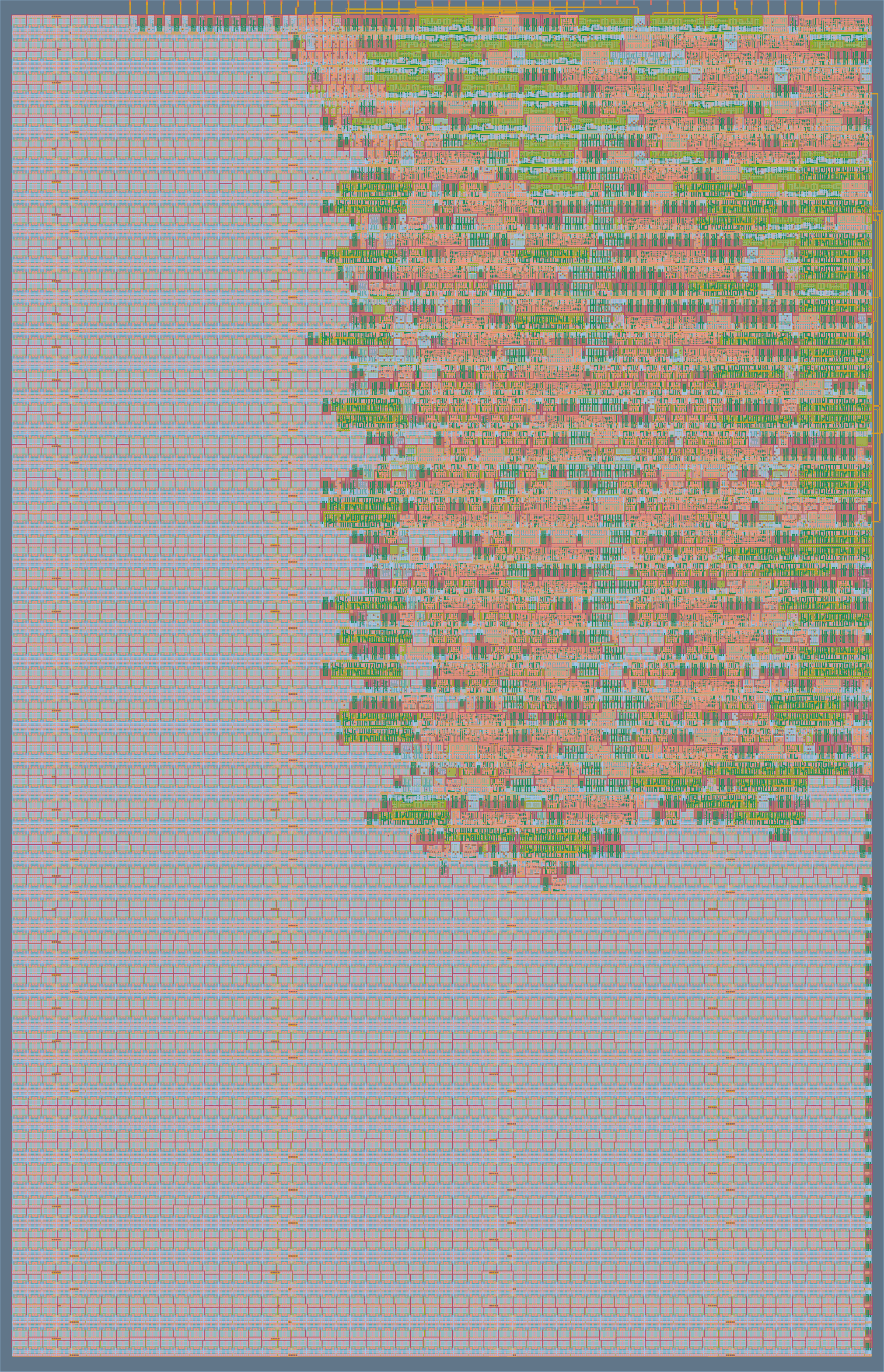
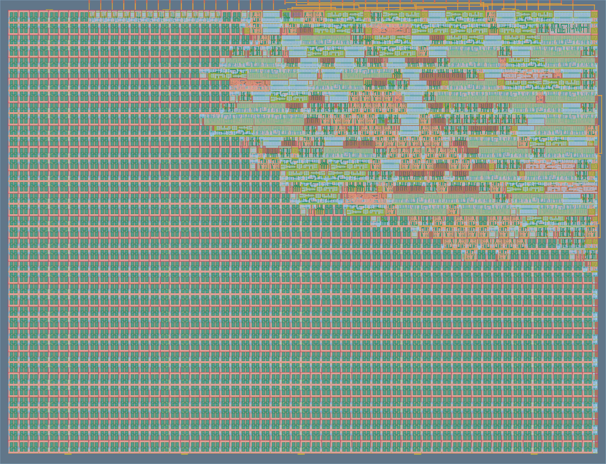
A few more bugs later and https://github.com/ygdes/miniMAC_IHP/actions/runs/24273856501:
The size is roughly the same but the double-adder makes it 2× faster in the end, since I could push to 5ns cycle time (at the cost of quite a few buffers). The IO can't stand 200MHz so it's an exercise and an exploration, which is useful in itself.
![]()
now if it worked at 200MHz, that would be 400MBytes per second, or 4Gbps, almost a Gen2 PCIe link.
-
Re-birth (2.2) : modulo code
04/08/2026 at 19:11 • 0 commentsThe architecture is settled and "just needs to be coded".
The C code is pretty simple, one variable and 3 lines are added per peer (ResX2 & ResA2).
// Decrambler
int Message_in, OpM, OpY2, ResX, X, Y, CX, CXin,
   CXout, Scrambled_out, ResX2;

void cycle_scrambler() {
  OpM = Message_in;
  OpY2 = Y;
  CXin = CX;
  ResX = OpM + OpY2 + CXin;
  X = ResX & MASK18;
  ResX2 = ResX + ADJUST;
  CX = (ResX | ResX2) >> 18;
  if (CX)
    X = ResX2 & MASK18;
  Scrambled_out = X;
}


// Decrambler
int Scrambled_in, OpM2, OpB2, B, A, ResA, CA, CAin,
    CAout, Message_out, error, ResA2;

void cycle_descrambler() {
  OpM2 = Scrambled_in;
  OpB2 = (~B) & MASK18;
  CAin = CA;
  ResA = OpM2 + OpB2 + CAin;
  A  = ResA & MASK18;
  ResA2 = ResA + ADJUST;
  CA = (ResA | ResA2) >> 18;
  if (CA)
    A = ResA2 & MASK18;
  Message_out = A & MASK17;
  error = (A >> 17 ) & 1;
}
Aaaand it doesn't work.
As usual the encoder is fine but the decoder is a hot jacuzzi of "what's going on ?"
It took a while (again) but this version finally works:
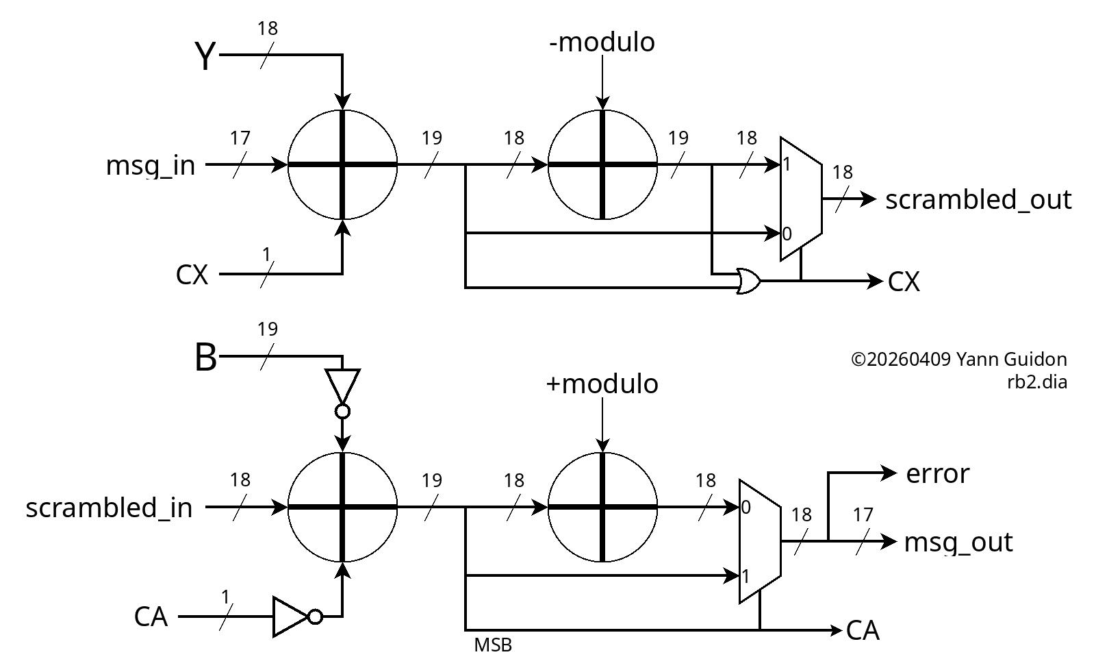
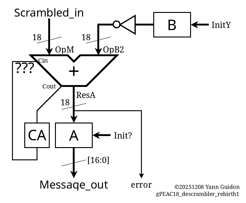
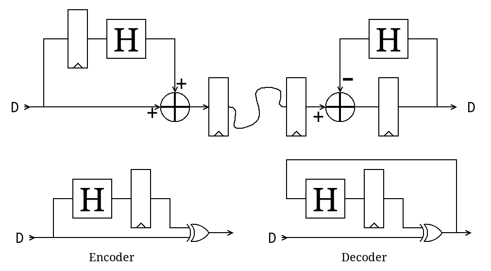
void cycle_descrambler() {
  OpM2 = Scrambled_in;
  OpB2 = (~B)&MASK19;        /// <=== !!!
  CAin = CA^1;               /// <=== !!!
  ResA = OpM2 + OpB2 + CAin;
  A  = ResA & MASK18;
  ResA2 = A + MODULUS;       /// <=== !!!
  CA = ((ResA >> 18) &1);    /// <=== !!!!!!!!
  if (CA)
    A = ResA2 & MASK18;
  Message_out = A & MASK17;
  error = (A >> 17 ) & 1;
}
It's still quite unconventional and hard to grasp so a diagram is required.
![]()
The key detail is that the descrambler is not a modular addition, unlike the scrambler. Logically it's a modular subtraction and this changes a lot of non-obvious details. In particular:
- the scrambler works in the unsigned, positive range, from 0 to 2×mod, hence the OR to detect overflow,
- the descrambler, starting from range 0 to mod, subtracts another value from 0 to mod, so the output range goes from -mod to +mod, hence the sign bit is the MSB from the first "inverted addition" and no OR this time.
The C code generates a longer list of test vectors, such that the thin slice of invalid values (from modulo to 262144) get corrected:
[   1234,  225196],
[  38650,    4498],
[  76066,   41915],
[ 113482,   79331],
[  19826,  243789],
[  57242,   23090],
[  94658,   60507],
[   1002,  224965],
[  38418,    4266],
[  75834,   41683],
[ 113250,   79099],
[  19594,  243557],
[  57010,   22858],
[  94426,   60275],
[    770,  224733],
[  38186,    4034],
[  75602,   41451],
[ 113018,   78867],
[  19362,  243325],
[  56778,   22626],
[  94194,   60043],
[    538,  224501],
[  37954,    3802],
[  75370,   41219],
[ 112786,   78635],
[  19130,  243093],
[  56546,   22394],
[  93962,   59811],
[    306,  224269],
[  37722,    3570],
[  75138,   40987],
[ 112554,   78403],
[  18898,  242861],
[  56314,   22162],
[  93730,   59579],
[     74,  224037],
[  37490,    3338],
[  74906,   40755],
[ 112322,   78171],
[  18666,  242629],
[  56082,   21930],
[  93498,   59347],
[ 130914,   96763],
[  37258,    3107],
[  74674,   40523],
[ 112090,   77939],
[  18434,  242397],
[  55850,   21698],
[  93266,   59115],
[ 130682,   96531],
[  37026,    2875],
[  74442,   40291],
[ 111858,   77707],
[  18202,  242165],
[  55618,   21466],
[  93034,   58883],
[ 130450,   96299],
[  36794,    2643],
[  74210,   40059],
[ 111626,   77475],
[  17970,  241933],
[  55386,   21234],
[  92802,   58651],
[ 130218,   96067],
[  36562,    2411],
[  73978,   39827],
[ 111394,   77243],
[  17738,  241701],
[  55154,   21002],
[  92570,   58419],
[ 129986,   95835],
[  36330,    2179],
[  73746,   39595],
[ 111162,   77011],
[  17506,  241469],
[  54922,   20770],
[  92338,   58187],
[ 129754,   95603],
[  36098,    1947],
[  73514,   39363],
[ 110930,   76779],
[  17274,  241237],
[  54690,   20538],
[  92106,   57955],
[ 129522,   95371],
[  35866,    1715],
[  73282,   39131],
[ 110698,   76547],
[  17042,  241005],
[  54458,   20306],
[  91874,   57723],
[ 129290,   95139],
[  35634,    1483],
[  73050,   38899],
[ 110466,   76315],
[  16810,  240773],
[  54226,   20074],
[  91642,   57491],
[ 129058,   94907],
[  35402,    1251]
The VHDL code is almost a formality at this point, and it was pretty smooth this time. It still looks messy because of the use of signals instead of variables (to ease comparisons with gtkwave) but that's merely a formatting detail.
    procedure init_scrambler is
    begin
      X <= INIT_X;  -- does not matter yet
      Y <= INIT_Y;
      CX<= '0';
      wait for 1 ns;
    end procedure;

    procedure cycle_scrambler is
    begin
      wait for 1 ns;

      OpM <= '0' & Message_in; -- pad MSB
      OpY2 <= Y;
      CXin <= CX;
      wait for 1 ns;

      ResX <= unsigned('0' & OpM  & '1' )
            + unsigned('0' & OpY2 & CXin);
      wait for 1 ns;

      CXout <= std_ulogic(ResX(19));
      X <= std_ulogic_vector(ResX(18 downto 1));
      wait for 1 ns;

      ResX2 <= unsigned('0' & ResX(18 downto 1))
             + unsigned('0' & ADJUST);  -- no carry in here
      wait for 1 ns;

      CXout2 <= std_ulogic(ResX2(18));
      wait for 1 ns;

      CX <= CXout or CXout2;
      wait for 1 ns;

      if CX /= '0' then
        X <= std_ulogic_vector(ResX2(17 downto 0));
        wait for 1 ns;
      end if;

      Scrambled_out <= X;
      wait for 1 ns;
    end procedure;

---------------------------------------------
    procedure init_descrambler is
    begin
      --A <= INIT_X;  -- does not matter yet
      B <= INIT_Y;
      CA<= '0';
    end procedure;

    procedure cycle_descrambler is
    begin
      wait for 1 ns;

      OpM2 <= Scrambled_in;
      OpB2 <= not B;
      CAin <= not CA;
      wait for 1 ns;

      ResA <= unsigned('0' & OpM2 & '1' )
            + unsigned('1' & OpB2 & CAin); -- OpB2 is sign-extended
      wait for 1 ns;

      CAout <= std_ulogic(ResA(19));
      A <= std_ulogic_vector(ResA(18 downto 1));
      wait for 1 ns;

      if CAout /= '0' then
        ResA2 <= ResA(18 downto 1)
               + unsigned(MODULO);  -- no carry in or out here
        wait for 1 ns;
        A <= std_ulogic_vector(ResA2);
        wait for 1 ns;
      end if;

      CA <= CAout;
      Message_out <= A(16 downto 0);
      error <= A(17);
      wait for 1 ns;
    end procedure;
And a lot of moving data around in various aliases, too, because I planned a 2-cycle circuit with MUXes but there are fewer intermediary results now. And it passes 100 test vectors, I'll cleanup later.
One problem remains: ResA adds 19 bits and not 18 so I must find how to drop these constant bits.
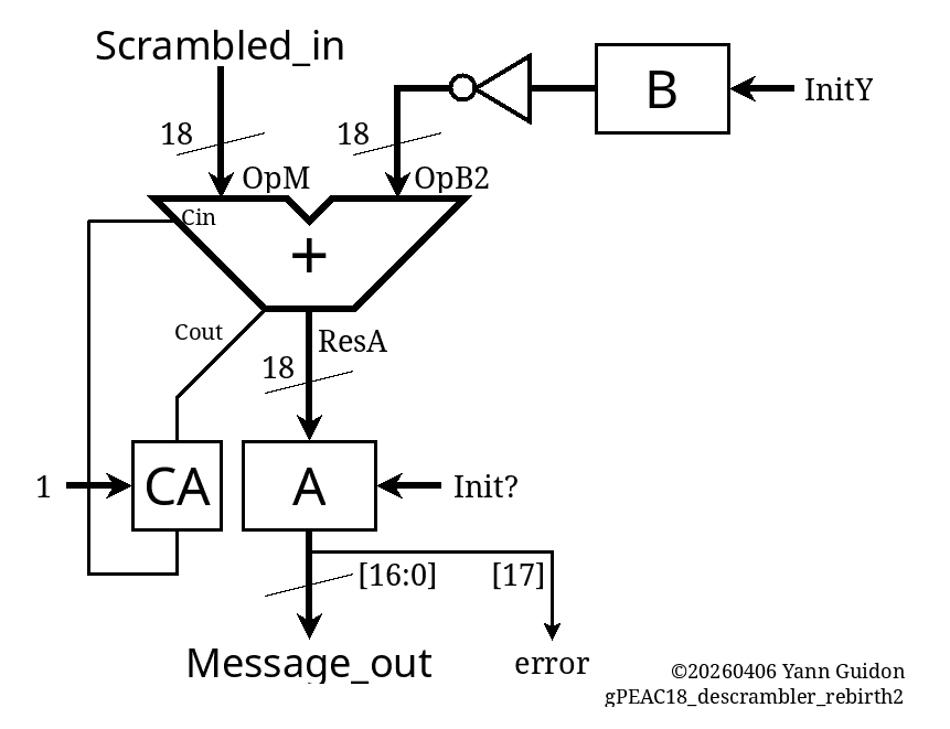
It's only a matter of inverting the carry signal then:
void init_descrambler() {
  A=-1;
  B=INIT_Y;
  CA=1;     // <==
}

void cycle_descrambler() {
  OpM2 = Scrambled_in;
  OpB2 = (~B)&MASK18;         // <==
  CAin = CA;                  // <==
  ResA = OpM2 + CAin + OpB2;
  A  = ResA & MASK18;
  ResA2 = A + MODULUS;
  CA = (ResA >> 18) & 1;
  if (!CA)                    // <==
    A = ResA2 & MASK18;
  Message_out = A & MASK17;
  error = (A >> 17 ) & 1;
}
And the VHDL follows:
    procedure init_descrambler is
    begin
      --A <= INIT_X;  -- does not matter yet
      B <= INIT_Y;
      CA<= '1';
    end procedure;

    procedure cycle_descrambler is
    begin
      wait for 1 ns;

      OpM2 <= Scrambled_in;
      OpB2 <= not B;
      CAin <= CA;
      wait for 1 ns;

      ResA <= unsigned('0' & OpM2 & '1' )
            + unsigned('0' & OpB2 & CAin);
      wait for 1 ns;

      CAout <= std_ulogic(ResA(19));
      A <= std_ulogic_vector(ResA(18 downto 1));
      wait for 1 ns;

      if CAout /= '1' then
        ResA2 <= ResA(18 downto 1)
               + unsigned(MODULO);  -- no carry in or out here
        wait for 1 ns;
        A <= std_ulogic_vector(ResA2);
        wait for 1 ns;
      end if;

      CA <= CAout;
      Message_out <= A(16 downto 0);
      error <= A(17);
      wait for 1 ns;
    end procedure;
And after so much good preparation, the Verilog compiles and simulates on first try (or so).
.
Reducing the speed back to 10ns (easier/faster convergence), we get https://github.com/ygdes/miniMAC_IHP/actions/runs/24197988265
![]()
I think the 100MHz clock still gives a wide margin. I'll see later when synthesis crumbles with a full circuit.
The Hammer18 circuits and all the registers are included. Routing looks nice, with moderate contention on the top layers. There is more than ample margin to add the "Y" path !
-
Re-birth (2.1) : constant-modulo adders
04/08/2026 at 11:34 • 0 commentsI didn't mean to reinvent the wheel but the recent experience with the tape-outs has taught me to reduce DFFs as much as possible. So as I return to the previous 2-cycle modular addition, which I thought was already reasonably efficient, and found that this circuit leads to mutual race conditions (which would explain the messy development several months ago), I understand that I must find a better approach.
The last log 139. Re-birth (2) : the modulo. hints that there have been studies and Google led me to
Hiasat, Ahmad. (2002). High-speed and reduced-area modular adder structures for RNS. Computers, IEEE Transactions on. 51. 84-89. 10.1109/12.980018.
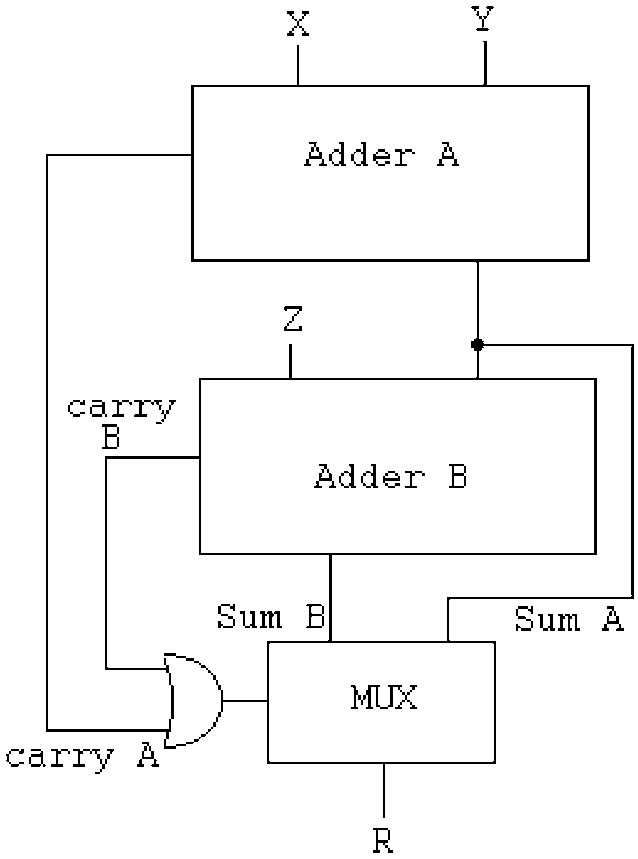
It starts there https://www.researchgate.net/figure/The-modular-adder-proposed-by-Bayoumi-and-Jullien-18_fig1_3044437 with a simple diagram from a different paper:
![]()
Fig1 : The modular adder proposed by Bayoumi and Jullien [18]. This inverts the order of the adders that I intended before but fair enough. There are 3 critical datapaths back-to-back:
- Adder A
- Adder B (though some overlap is possible since they both start from the LSB)
- the fanout for the MUX
-------------------------------------------------------------------------------------------
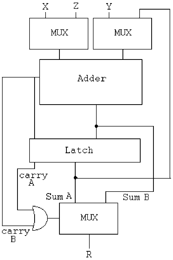
Fun fact: figure 2 of the paper describes a 2-cycle version ("Dugdale" topology), similar to the method I developed previously. The use of a latch (and not DFF) at this position is pretty smart but the size increase is still significant, adding 3 MUX.
The Dugdale topology trades a constant adder for 3 MUX, 1 latch and 1 added cycles, which is not favourable when adders are relatively cheaper.
![]()
-------------------------------------------------------------------------------------------
More studies:
Pipelined Two-Operand Modular Adders
https://www.radioeng.cz/fulltexts/2015/15_01_0148_0160.pdf
(Maciej CZYŻAK, Jacek HORISZNY, Robert SMYK) 2015 (13 years after Hiasat & Ahmad)-------------------------------------------------------------------------------------------
The papers propose various enhancements, so the B&J circuit above, even though not optimal:
- is a good starting point
- would be somewhat optimised in our back by the synth tools
- has less overall latency than a 2-cycle version (since the 2 carry chains can be close to each other and the LSB of Adder B can be evaluated soonder)
- does not require over-registering like the 2-cycle version
- promises ways to optimise later, when there is more time.
The strategy now is to "isolate" the mod adder, such that it can be reworked after the first crude version proved it works. The adder is a bit larger than before but, considering the other factors, it's the fastest and most compact reasonable way to implement it in an ASIC, where the adder seems to be less of a concern than in an FPGA.
And this leaves some potential optimisations on the table, for later.
.
-
Re-birth (2) : the modulo.
04/07/2026 at 00:28 • 0 commentsThe last log 138. Re-birth (1) has found 3 more coding flaws and there are probably even more.
At this moment, I start to doubt the choice of the modulus, because being so close to 2^18 makes it pretty unlikely to overflow and create a carry (remember: the carry creates an additional avalanche). But then I forget that Y changes too (it's fixed for now) and I'll have to observe the activity of the carries. It will be interesting to compare the different values...
The principle of the dual cycle is to pass the first sum into the adder again, but adding a constant (derived from the modulus) and see if the result overflows. If it does, the new (adjusted, wrapped-around) sum is written to the register, otherwise it is not modified.
It's simple but not obvious because the whole thing mixes the numerical bases: the first phase is mod 262144 and the second phase is mod 258114, so there is an adjustment of 4030.
Managing the carry bit is notoriously tricky in this situation and I have lost some hair already...
................................................
Now something occurs to me. There could be a way out of this madness.
First: I have noticed how ASIC have a different balance from FPGA. DFFs are 3x more costly than typical logic gates, which means that an adder is more economical than a whole pipeline regsiter.
Second: It may be better to chain the adders, instead of cycling and sequencing and managing. This makes a slower clock but it does more in one period. Particularly if the 2nd add is a constant, which would use fewer gates.
Third (and this is the stroke of genius that didn't occur to me until this morning): what if the constant add is moved upstream so it doesn't bother us? There would be a simpler pipeline and less complexity...
Fourth: the pre-add would also work as error detection, because it does the work of the comparator.
Except that the adjustment is conditional...
Engineering really is the art of moving problems around.
................................................
Back to the circuit. The RB1 does one thing: out = in + Y.
In the RB2 (with modulo implemented) one way to know whether it has overflown is to check the carry bit, but there are 4030 cases out of 264144 (1 chance in 65, roughly, actually it's more complicated than that) that the sum is actually between the modulus and 2^18. The low chance makes me think again that the modulus is too high, but the 2nd turn is still necessary, if only because the result provides the corrected sum.
Actually we want 2 things:
- sum1 = in + Y
- sum2 = in + Y + 4030
Then we select the result according to the carry bit of sum2. This is a rather typical configuration that I have seen in previous works.
................................................
I think I have uncovered a 5th flaw in the previous design, probably present in the VHDL "reference" as well: the A/X pipes are fed with B/Y but these values change with the phase, because they are not stabilised/registered => race condition
No wonder I had such a bad time making it work !!!................................................
Now there are 2 ways to make the modulo adder work.
- sum1 = in + Y
- sum2 = sum1 + 4030
(as I have seen somewhere and it looks good) or
- sum1 = in + 4030
- sum2 = sum1 + Y
And I'd love to use this since this would reduce the effort on the Y/B pipelines that reuse the input. Pre-adjusting the input saves multiplexers (constant or classic) so in a way, this simplifies the system.
This adds an adder in the pipeline but with two alternating constants (0 and 4030).
However I recently found that a 2-cycles system needs more registers to prevent race conditions => A one-cycle solution would prevent this !
Furthermore, it appears that factoring the adjustment into the input does not save much. There is still the need for the two bigger adders, and the added temporary registers bloat the system.
................................................
Fortunately I have found a paper that covers modulo-M adders, not just 2^n+1 and 2^n-1 (which amounts to some form of EAC / End-Around-Carry).
-
Re-birth (1)
03/31/2026 at 11:39 • 0 commentsThe last log 137. iHP26a - post mortem explains why and how the whole thing could be rebuilt almost from scratch, so let's now start with the basic integrator-differentiator pair. It's just a 18-bit version, the modulus is added later. Moreover, each step requires an identical/equivalent representation in C (JS), VHDL, Verilog and diagram.
For the first step, we have a simple accumulator X, adding the (fixed) register Y to the incoming message. The decumulator does the reverse, subtracting B from the incoming message. It's not hard but keeping all representations in sync takes some efforts. (and yes, these are just registers, not accumulators, but I had to come up with a word...)
And even this simple circuit is not totally obvious. The dataflow is easy and the encoder is simple but the carry requires a lot more thinking in the receiver.
![]()
So how is the carry processed in the receiver ? what inversion is needed and where ?
![]()
CA would be reset to 0.
A subtraction needs the Cin to be set.
But I remember that there is a double-inversion somewhere and some carry was no inverted.And I can't even get something as simple as above right on the first try in C, I must remove even more: the carry, the inversion...
................................................................
But I finally managed to get something that works in C.
#define MASK17  ((1<<17)-1)
#define MASK18  ((1<<18)-1)
#define MODULUS (258114)
#define ADJUST  (262144-MODULUS)
#define INIT_X   (56247) // "01101101110110111"
#define INIT_Y  (2*(111981)) // "11011010101101101"  2× to trigger carry

// Scrambler
int Message_in, OpM, OpY2, ResX, X, Y,
    CX, CXin, CXout, Scrambled_out;

void init_scrambler() {
  X=INIT_X;  // does not matter yet
  Y=INIT_Y;
  CX=0;
}

void cycle_scrambler() {
  OpM = Message_in;
  OpY2 = Y;
  CXin = CX;
  ResX = OpM + OpY2 + CXin;
  X = ResX & MASK18;
  CX = ResX >> 18;
  Scrambled_out = X;
}

// Decrambler
int Scrambled_in, OpM2, OpB2, B, A, ResA,
    CA, CAin, CAout, Message_out, error;

void init_descrambler() {
  A=-1;
  B=INIT_Y;
  CA=1;
}

void cycle_descrambler() {
  OpM2 = Scrambled_in;
  OpB2 = (~B) & MASK18;
  CAin = CA;
  ResA = OpM2 + OpB2 + CAin;
  A  = ResA & MASK18;
  CA = ResA >> 18;
  Message_out = ResA & MASK17;
  error = (ResA >> 17 ) & 1;
}
I modified INIT_Y to force the carry condition, don't worry.
CA and CX are inverted from each other, but it comes from the computation, no need of explicit inverstion. Only initialise them properly: CX=0, CA=1. It's simple yet very not obvious...
This inversion situation needs proper modelling and explanation.
- CX and CA are complementary because the sum of INIT_Y and 1 + ~INIT_Y gives 1<<18.
- CX goes 1 when Message_in >= (1 + ~INIT_Y)
- conversely CA goes 1 when Scrambled_in >= INIT_Y (or something ... I'm still confused)
- Both addends make the whole word go +(1<<18) so there IS a carry in any case, either in CA or CX.
- In the end, CAout is fed directly into CAin. So we can remove the question marks.
![]()
The code is in rb1.c, it generates these test vectors:
[     42,  224004],
[  24455,  248417],
[  48868,   10686],
[  73281,   35100],
[  97694,   59513],
[ 122107,   83926],
[  15448,  239411],
[  39861,    1679],
[  64274,   26093],
[  88687,   50506],
[ 113100,   74919],
[   6441,  230404],
[  30854,  254816],
[  55267,   17085],
[  79680,   41499],
[ 104093,   65912],
[ 128506,   90325],
[  21847,  245810],
[  46260,    8078],
[  70673,   32492],
[  95086,   56905],
[ 119499,   81318],
[  12840,  236803],
[  37253,  261215],
[  61666,   23484],
[  86079,   47898],
[ 110492,   72311],
[   3833,  227796],
[  28246,  252208],
[  52659,   14477],
Now, the VHDL and mapped Verilog versions should be easy to deduce.
.
Well, VHDL certainly was (almost) a walk in the park. Encoding goes like this:
  -- encoder
  signal Message_in    : std_ulogic_vector(16 downto 0);
  signal Scrambled_out : std_ulogic_vector(17 downto 0);
  signal CX, CY : std_ulogic;
  signal  X,  Y : std_ulogic_vector(17 downto 0);
  signal OpM, OpY2: std_ulogic_vector(17 downto 0);
  signal CXin,  CYin, CXout, CYout : std_ulogic;
  signal ResX, ResY : unsigned(19 downto 0);

    procedure init_scrambler is
    begin
      X <= INIT_X;  -- does not matter yet
      Y <= INIT_Y;
      CX<= '0';
      wait for 1 ns;
    end procedure;

    procedure cycle_scrambler is
    begin
      wait for 1 ns;

      OpM <= '0' & Message_in; -- pad MSB
      OpY2 <= Y;
      CXin <= CX;
      wait for 1 ns;

      ResX <= unsigned('0' & OpM  & '1' )
            + unsigned('0' & OpY2 & CXin);
      wait for 1 ns;

      CXout <= std_ulogic(ResX(19));
      X <= std_ulogic_vector(ResX(18 downto 1));
      wait for 1 ns;

      CX <= CXout;
      Scrambled_out <= X;
      wait for 1 ns;
    end procedure;
I replaced variables with signals so gtkwave could see them. All the "wait for"s bloat the code but it does not matter.
Decoding is similar.
  -- decoder
  signal Scrambled_in : std_ulogic_vector(17 downto 0);
  signal Message_out  : std_ulogic_vector(16 downto 0);
  signal CA, CB,  CAin,  CBin, CAout, CBout, error : std_ulogic;
  signal  A,  B : std_ulogic_vector(17 downto 0);
  signal OpM2, OpB2: std_ulogic_vector(17 downto 0);
  signal ResA, ResB : unsigned(19 downto 0);

    procedure init_descrambler is
    begin
      --A <= INIT_X;  -- does not matter yet
      B <= INIT_Y;
      CA<= '1';
    end procedure;

    procedure cycle_descrambler is
    begin
      wait for 1 ns;

      OpM2 <= Scrambled_in;
      OpB2 <= not B;
      CAin <= CA;
      wait for 1 ns;

      ResA <= unsigned('0' & OpM2 & '1' )
            + unsigned('0' & OpB2 & CAin);
      wait for 1 ns;

      A <= std_ulogic_vector(ResA(18 downto 1));
      CAout <= std_ulogic(ResA(19));
      wait for 1 ns;

      CA <= CAout;
      Message_out <= A(16 downto 0);
      error <= A(17);
      wait for 1 ns;
    end procedure;
It matches the C code and it's all in rb1.vhdl.
.
.
For the Verilog version.... rain is pouring on the proverbial park.
- first I had to come up with a translation layer to insulate the PDK from pesky variations between the iHP G2 and CMOS5L version. That has given https://github.com/YannGuidon/IHP_SG13_cells after a lot of wrangling with sed.
- but then, I need a functioning place to put the files, and I want to reuse https://github.com/ygdes/miniMAC_5Lwithout touching it. This is already a fork and github does not let me fork it further... So I guess the only remaining solution is to restart from scratch. So I must clone everything locally, treat all the files and then reupload them in a new instance of the original SG13G2 template... I hate git.
But in the end, coding has resumed.
.
Already I can find a few errors, such as
- B initialised to the wrong value,
- the CA bit reset instead of set.
- INIT_X And INIT_Y being ... wroooong.... (dffen_rs_x18 was bork)
Add to this the timing bug of the output multiplexer and you understand why the first tape out had no chance of working as intended.
But finally, the verilog version of the encoder is conform, at last !
     0.00ns INFO     cocotb.tb          Reset
 50000.00ns INFO     cocotb.tb          Starting bypass Mode
2120000.00ns INFO     cocotb.tb         RB1 Scrambling Mode
 - in: 42   found: 224004   expected: 224004
 - in: 24455   found: 248417   expected: 248417
 - in: 48868   found: 10686   expected: 10686
 - in: 73281   found: 35100   expected: 35100
 - in: 97694   found: 59513   expected: 59513
 - in: 122107   found: 83926   expected: 83926
 - in: 15448   found: 239411   expected: 239411
 - in: 39861   found: 1679   expected: 1679
 - in: 64274   found: 26093   expected: 26093
 - in: 88687   found: 50506   expected: 50506
 - in: 113100   found: 74919   expected: 74919
 - in: 6441   found: 230404   expected: 230404
...
https://github.com/ygdes/miniMAC_IHP/actions/runs/24052860568/job/70152404603
Then test the decoder and the loopback...
and it passes all tests and synthesis: https://github.com/ygdes/miniMAC_IHP/actions/runs/24056359563 (including the Hammer here)
![]()
.
-
iHP26a - post mortem
03/30/2026 at 17:14 • 0 commentsThe project https://github.com/YannGuidon/miniMAC_tx got tape-out-ed on ihp26a but the design is bork and could at best over-scramble noise...
Then I tried my luck again with https://github.com/ygdes/miniMAC_5L on IHP 0p4 and at least the Hammer18 circuits work as intended, but the gPEAC18 resisted again and didn't make it.
gPEAC is indeed a very delicate piece of circuit and the VHDL took ages to get right. I have the C reference code, the VHDL RTL but the Verilog structural gate-mapped version wouldn't work. Something somewhere is always working wrong, the debugging is excruciating (cumbersome and slowwww), Verilog is a PITA and the VHDL variables (in the RTL code) are not exposed to gtkwave, so it's impossible to compare with the Verilog version where all wires are visible signals.
Today, the Verilog code for gPEAC is complete but fails to comply with the C and VHDL code. And I see no sane and reliable way to find what is wrong. So I'm forced to rebuild the WHOLE thing from scratch.
The plan is to redesign everything simultaneously, starting from the simplest circuit and adding new circuits little by little, in four versions:
- C reference
- VHDL RTL
- Schematic with precise annotations
- Verilog gates
To get from the current state to a smaller, easily testable circuit, both the encoder and decoder must be cut down:
- The B pipeline must be cut from the A, the Y removed from X.
- The pipelines get reduced to one cycle
then it's rather easy to rebuild from scratch...
Fortunately 135. Number comparison with the iHP PDK does not need to change.
(update : well ok it did, a minor tweak)
-
Mapping the pipeline to iHP PDK
03/21/2026 at 14:46 • 0 commentsIt's tempting to just plop the VHDL source code and let the synthesiser do the heavy lifting.
But the pipeline is in Verilog and I use structural code only so I must map (actually synthesise) the circuits by hand.
For this a clear view of the circuit is essential and circuitJS helps, but doing that also makes me reconsider several choices and the VHDL coding style must be deeply adapted.
The last log has mapped the comparator, so that's one thing left on the list.
The remaining circuits are inventoried.
- The adder : I'll use dumb RTL style since I'm not yet operational with Jerem's Logilib. No time to dig further, it will work.
- The DFF: there are three cases.
- X and T are initialised with INIT_X, have feedback/enable
- Y and B are initialised with INIT_Y, have feedback/enable
- A is not initialised, has feedback/enable
- There are muxes, to select the operands during each phase.
- OPM is a basic mux2 done by mux2_x18() (for both sides)
- OPX, OPY2 and OPT are muxed with a constant ADJUST.
- OPB2 is muxed with the modulus and B is inverted.
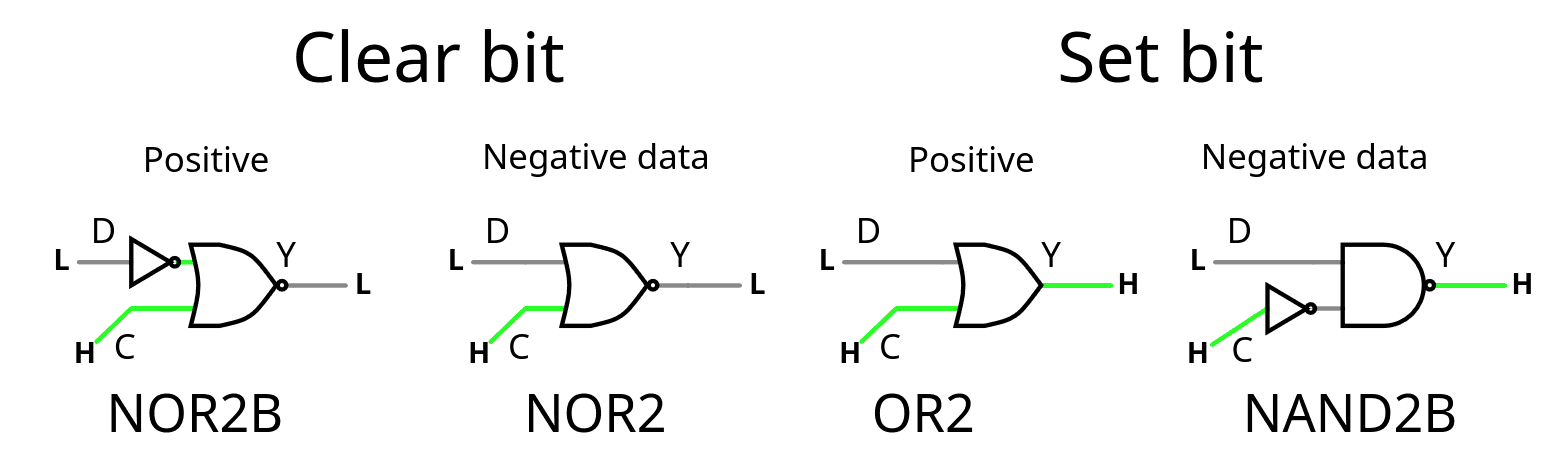
That's 2 circuits to create here, one just forces the constant, the other also inverts the operand. Here again the PDK does a great job. See the simulations :
![]()
So that's 2 modules to write using only these gates: ConstAdjOrPass() and ConstModOrNeg().
And that's about it for the bulk of the datapath.
-
Number comparison with the iHP PDK
03/21/2026 at 01:28 • 0 commentsIt didn't go as expected.
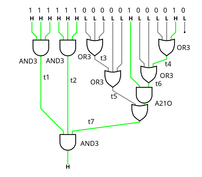
The comparator doesn't use NAND/NOR because it actually makes it larger and/or bigger, and what matters is the critical path along the cascade. Fortunately A21OI is here and helps! the 4 gates are not in the critical datapath so over-optimising for speed is less interesting than optimising for area.
![]()
The tested source code is there : https://github.com/YannGuidon/miniMAC_tx/blob/main/src/gPEAC18.v
/* This module compares a 18-bit number to the modulus.
   Compare a bitvector with the constant 258114 = 0x3F042 = 111111000001000010
   Any number equal or above raises X */
module Compare_modulus(
    input wire [17:0] A,
    input wire En,
    output wire X
);
  wire t1, t2, t3, t4, t5, t6, t7, _unused;
  assign _unused = A[0]; // The LSB has no effect.
  // first layer
  (* keep *) sg13g2_and4_1 L1a3_1(.X(t1), .A(A[17]), .B(A[16]), .C(A[15]), .D(En));
  (* keep *) sg13g2_and3_1 L1a3_2(.X(t2), .A(A[14]), .B(A[13]), .C(A[12]));
  (* keep *) sg13g2_or3_1  L1o3_1(.X(t3), .A(A[11]), .B(A[10]), .C(A[ 9]));
  (* keep *) sg13g2_or3_1  L1o3_2(.X(t4), .A(A[ 3]), .B(A[ 2]), .C(A[ 1]));
  // 2nd layer
  (* keep *) sg13g2_or3_1  L2o3_3(.X(t5), .A(t3),    .B(A[ 8]), .C(A[ 7]));
  (* keep *) sg13g2_or3_1  L2o3_4(.X(t6), .A(t4),    .B(A[ 5]), .C(A[ 4]));
  // 3rd layer
  (* keep *) sg13g2_a21o_2 L3ao_1(.X(t7), .A1(t6),   .A2(A[6]), .B1(t5));
  // Last stage
  (* keep *) sg13g2_and3_1 L4a3_3(.X( X), .A(t1),    .B(t2),    .C(t7));
endmodule
.
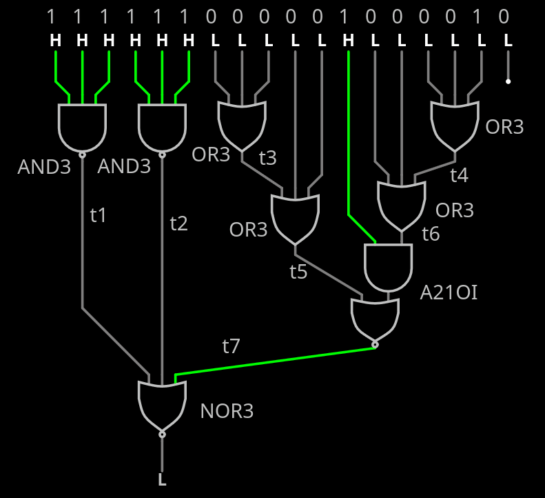
I just realised I could do some bubble-pushing and shave a bit...
The A21O can be turned into A21OI then feed to the AND3 turned into NOR3.
The other AND3s are turned to NAND3s.
![]()
.
-
Testing the Hammer
03/10/2026 at 04:18 • 0 commentsI have a first functional circuit in ASIC and I must write the Python code that tests the sea-of-xor.
There are 19 key values to test: 0 and the 18 single-bit-at-1 configurations.
Then throw a few "random" values for good measure, since the rest should be a linear combination of all the 18 single-bit cases, right ? And the all-ones case of course.
But then the results of some test vectors could become vectors themselves. So some VHDL later and we get
111111111111111111  101011111000110100
000000000000000000  000000000000000000
000000000000000001  110111011111011001
000000000000000010  110111011111011111
000000000000000100  110111101111011111
000000000000001000  110111101110011111
000000000000010000  010111100110110101
000000000000100000  110001101011001010
000000000001000000  000000011111111000
000000000010000000  101110111001000000
000000000100000000  111111000010100000
000000001000000000  111111011111111001
000000010000000000  111110111111111001
000000100000000000  111110111111110101
000001000000000000  001101111111010101
000010000000000000  000111100010110101
000100000000000000  110111000000100110
001000000000000000  111111000000101100
010000000000000000  100001001101110000
100000000000000000  000000011111111010
111111111000000000  011100010000010101
000000000111111111  110111101000100001
101010101010101010  100110111110100101
010101010101010101  001101000110010001
110111011111011001  011011011100100111
110001101011001010  000011011010101011
000000011111111010  110110111000100111
011011011100100111  101100110110001111
001101111111010101  111100010010000001
011011010110110101  011101101001011100
100100101001001010  110110010001101000
110110010001101000  101001010101001101
111100010010000001  001110001011100000
110110111000100111  101000101011111111
100110111110100101  101111000010110000
000011011010101011  100011000001110011
101000101011111111  110110010101011011
100011000001110011  101100010000011011
001110001011100000  101111110000110100
Now I must find again how Python encodes binary data.
.....
It seems to work.
![]()
excepts that it outputs MSB first.
I consider making a subcircuit just to implement and test the Hammer18 in 3 modes: direct, encode and decode
![]()
..
result : it works well.
![]()
and the current circuit uses only 22% of the tile.
Routing stats
Utilisation (%) Wire length (um) 21.265 17366 Cell usage by Category
Category Cells Count Fill decap fill 1742 OR xor2 or2 83 Flip Flops dfrbpq dfrbp sdfrbpq 69 Misc dlygate4sd3 67 Buffer buf 66 Multiplexer mux2 36 Inverter inv 21 Combo Logic a22oi 9 NOR nor4 4 AND and2 and4 2 357 total cells (excluding fill and tap cells)
The speed easily reaches 100MHz, can be pushed to 200MHz,
![]()
but the stats show that about half of the surface is DDFs, 1/4th is buffers/delays/fanouts, and 1/4 is logic gates...
Cell type report:                     Count     Area
Fill cell                              1742   20588.00
Buffer                                    3      21.77
Clock buffer                             23     493.52
Timing Repair Buffer                    107    1701.91
Inverter                                  9      48.99
Clock inverter                           12      65.32
Sequential cell                          69    3917.29
Multi-Input combinational cell          146    2104.70
Total                                  2111   28941.49
now, that makes you think..
-
Fixed the Hammer's RTL
03/07/2026 at 16:08 • 0 comments@alcim.dev wanted to help me with the tapeout and translated Hammer18.vhdl to Hammer18.v with his custom AI tools. So I had to verify everything in detail. To my surprise, the AI did not hallucinate anything, but it uncovered two typos in the original file!
Note: these typos did not affect the efficiency of the whole system, the change in error detection rate is insignificant, probably the same order of magnitude as using a different permutation, or swapping wires at the input or output. The correction was necessary for overall coherence reasons, and I expect other, better permutations will appear in the future so it was more important in December to move forward, with a "good enough" permutation and assess the overall system performance.
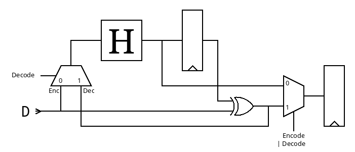
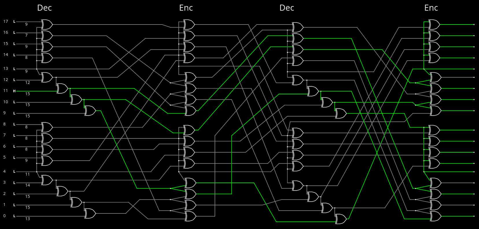
So I have uploaded the new version of Hammer18.vhdl and, for reference, here is the online sim and here is the corresponding diagram:
![]()
This was originally published in 124. Proof, pudding.
The two typos explain the last glitch in 126. Hammer = Hamming Maximiser
For more reference, the original permutations are
Perm1965 =
  forward(  3  5  9 17 16 10 15 12  1  2  0 14  6  7 13  8 11  4 )
  reverse( 10  8  9  0 17  1 12 13 15  2  5 16  7 14 11  6  4  3 )
Perm7515 =
  forward( 17  2 11  0  6 16  8  9 10 14  1  7 13 15  5 12  4  3 )
  reverse(  3 10  1 17 16 14  4 11  6  7  8  2 15 12  9 13  5  0 )
Perm4021 =
  forward(  4 17  6  5  1 15  7 14 16 13  0  9 10  8 12  2  3 11 )
  reverse( 10  4 15 16  0  3  2  6 13 11 12 17 14  9  7  5  8  1 )
but there was another glitch during the graphic transcription.
And the above permutations were designed and meant to be fed into more structured code, such that copy-pasting the above numbers would indeed avoid any typo. But that transformation will be for later.
.............................................................................................................
Another interesting realization is that the sea-of-xor, the latch and the combination-xor can work in different orders, allowing a better integration in the pipeline, where it amounts to only one XOR layer in the pipeline. Here are only a few possibilities:
![]()
TODO:
The new version of the file must be verified and the avalanche profile compared to the original diagram.
===> YES !
~/miniMAC$ ./runme_testHammer.sh
  total:200
 7   16   100001001101110000
 8   14   110111000000100110
 8    6   000000011111111000
 8    7   101110111001000000
 8    8   111111000010100000
 9   13   000111100010110101
 9   15   111111000000101100
 9   17   000000011111111010
 9    5   110001101011001010
11    4   010111100110110101
12   12   001101111111010101
13    0   110111011111011001
14    3   110111101110011111
15   10   111110111111111001
15    1   110111011111011111
15   11   111110111111110101
15    2   110111101111011111
15    9   111111011111111001
. .
TODO:
Solve the fanout imbalance issues
.
though so far, the Hammer circuit easily fits in the current 10ns cycle time.
Update : still flies at 5ns cycle time. I'm so impressed!
miniMAC - Not an Ethernet Transceiver
custom(izable) circuit for sending some megabytes over differential pairs.