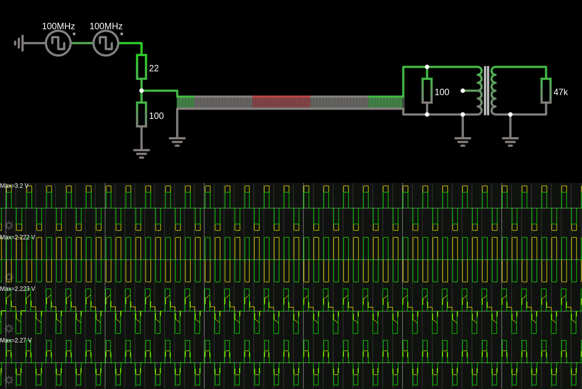
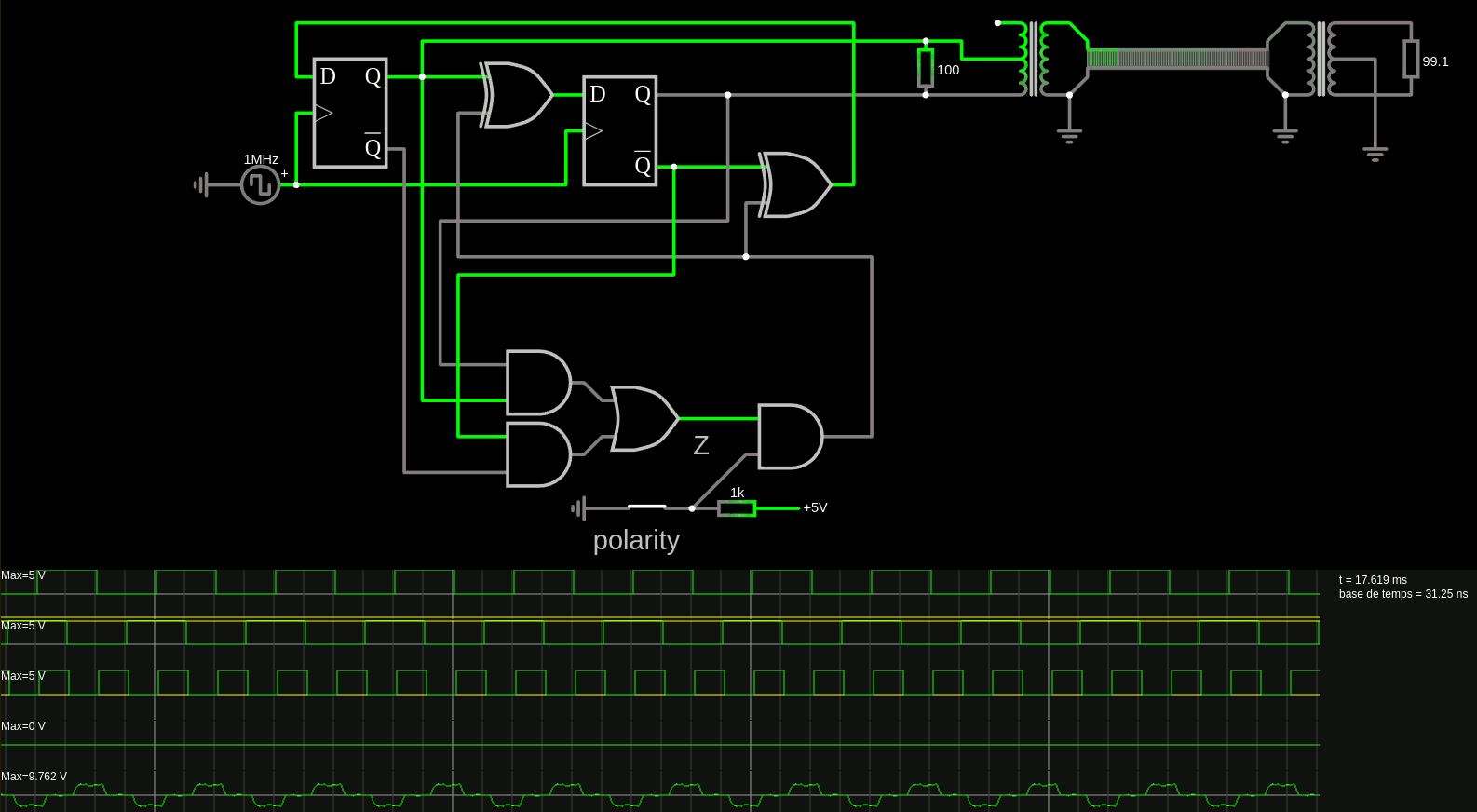
Here is the link. I have learned a few important things so far.

The big breakthrough was understanding that the transfo introduces distortion when current passes through it because it loads the ferrite with a magnetic field. This is why distortion disappeared when i put the terminator at the end of the transmission line (in front of the transfo) and the transformer acts as a signal isolator, which gets distorted as soon as the sink impedance increases > 47K
So the link above has no transfo at the source (yeah economy!!!). Otherwise, the current required to drive the magnetics would act like a weird low-pass with some occasional resonances depending on the cable length.
Source impedance does not look critical in the simulation, but I put a 100 ohm terminator anyway. This acts both as absorption of eventual reflection later in the cable, but also as a signal divider to keep the signal level in spec (around 2 to 2.5V). Correction : line level should be 1V.
The sense transformer at the end can be used in "amplifier mode" to double the amplitude of the detected signal, but when the line is "pristine", the amplitude reaches -5/+5V levels so an AGC is required. Said AGC can also work for baseline wander compensation : adjusting for gain and offset.
I'm not sure the idea of introducing "code violations" would work in practice : in a highly-distorting line (with the transfos messing with the signal, reducing the bandwidth dramatically), the break of the sequence heavily disrupts the signal, creating spikes sometimes and then muffling the next symbols. So I have to find a better system to add one optional bit per transmitted word.

Oh, pictures can be uploaded now !
But this sim was conducted at relatively low frequency, without inter-symbol interferences due to reflections on the twisted pair. And yes I have set the transfos' inductance to 350µ, as prescribed in the datasheets.
Of course all of this is simulations with a poorly characterised set of parts. Nothing like SPICE or better : real experiments. But these simulation have shown me a *lot* of effects, including droop ("baseline wander") and I have a better understanding of them now, so I will be less surprised when I encounter them in real life.
Finally : Falstad's CircuitJS might not be a professional, certified, calibrated, bug-free tool. But it has gotten even better over the years and is incredibly useful to quickly test ideas and check for common effects. The more subtle one require SPICE but it's much less convenient. Thank you Paul!
 Yann Guidon / YGDES
Discussions
Become a Hackaday.io Member
Create an account to leave a comment. Already have an account? Log In.