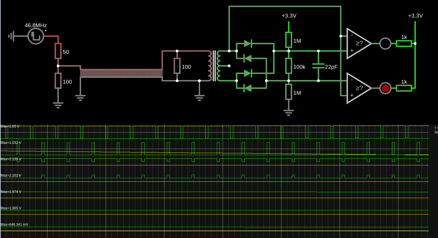
Trying to adjust the input level... sim here
As is, it doesn't work as expected yet but it's progressing.

it's crude but there are some ideas, such as : grounding the center tap capacitively might not be the best solution.
there are just 2 comparators to detect the +1 and -1 levels, level 0 is in-between.
The diodes serve 2 purposes : on top of performing envelope detection to set the gain (and charge the capacitor), they also define the margin between the top voltage and the detection level. Since the diode drop increases with current, which also increases with the input signal, the margin is reduced a bit when the signal is low. The diodes are 1N34s (germanium) to lower the drop, yet with some impedance.
I want to use the transfo in reverse so the line level is 1V and sensed at 2V, giving enough headroom for detection.
There is a resistive network 1M-100k-1M that "centers" the levels but has enough wiggle room to absorb "droop". The 100k-22pF has a RC time constant for the gain, but the ratio also affects the range of the AGC.
The topology is not quite right but the main ideas are here : separate the gain from the drift, each has their own time constants.
- Drift/Droop/wanter has a very short time constant, in the order of the microsecond,
- gain works on a much longer scale, milliseconds or seconds.
So 2 capacitors are required...
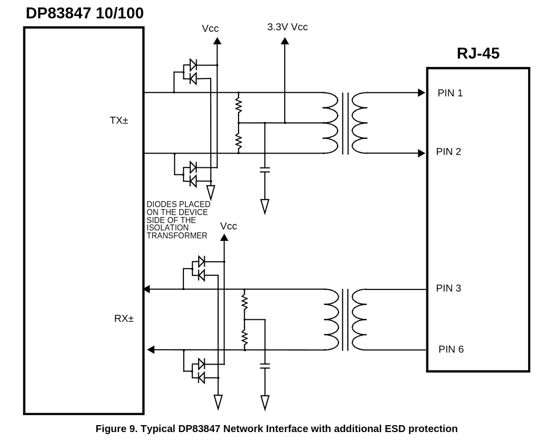
This is quite different from https://www.ti.com/lit/ds/symlink/dp83847.pdf

The TX' center tap is directly tied to 3.3V, which is extra weird because the transfo will trigger the ESD protection diodes if one side pulls down... Or you need Vcc = (2×3.3)-0.7=6V ?? Or the swing is shorter: high-side switching gives 5V-3.3V=1.7V but this creates a 3.4V peak-to-peak signal on the line, which is out of spec for Ethernet.
... and the RX secondary is somehow floating.
 Yann Guidon / YGDES
Discussions
Become a Hackaday.io Member
Create an account to leave a comment. Already have an account? Log In.