 Yann Guidon / YGDES
It's tempting to just plop the VHDL source code and let the synthesiser do the heavy lifting.
But the pipeline is in Verilog and I use structural code only so I must map (actually synthesise) the circuits by hand.
For this a clear view of the circuit is essential and circuitJS helps, but doing that also makes me reconsider several choices and the VHDL coding style must be deeply adapted.
The last log has mapped the comparator, so that's one thing left on the list.
The remaining circuits are inventoried.
- The adder : I'll use dumb RTL style since I'm not yet operational with Jerem's Logilib. No time to dig further, it will work.
- The DFF: there are three cases.
- X and T are initialised with INIT_X, have feedback/enable
- Y and B are initialised with INIT_Y, have feedback/enable
- A is not initialised, has feedback/enable
- There are muxes, to select the operands during each phase.
- OPM is a basic mux2 done by mux2_x18() (for both sides)
- OPX, OPY2 and OPT are muxed with a constant ADJUST.
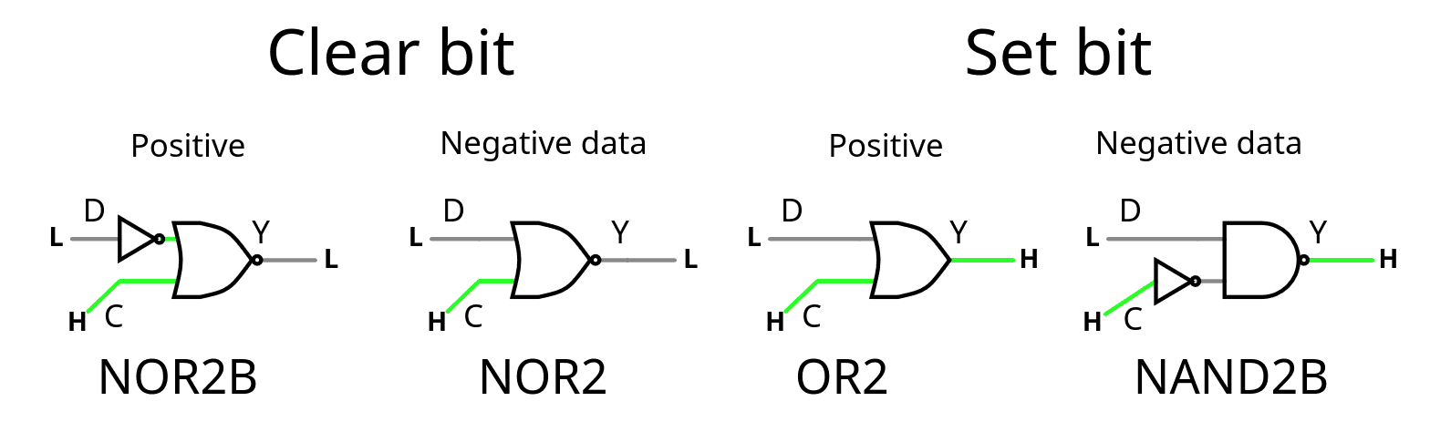
- OPB2 is muxed with the modulus and B is inverted.
That's 2 circuits to create here, one just forces the constant, the other also inverts the operand. Here again the PDK does a great job. See the simulations :
![]()
So that's 2 modules to write using only these gates: ConstAdjOrPass() and ConstModOrNeg().
And that's about it for the bulk of the datapath.
Discussions
Become a Hackaday.io Member
Create an account to leave a comment. Already have an account? Log In.