Yann Guidon / YGDES
Data transmission gets hard as you increase the bandwidth and not everything can be done with, or solved by, serial differential pairs. A dozen single-ended wires would do in many cases but the physics and protocols add even more constraints.
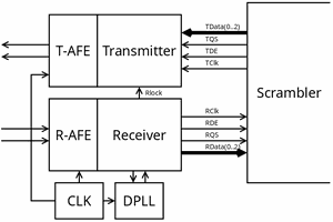
Communication between the MAC & PHY has been the subject of many logs already. Latest iteration was https://hackaday.io/project/203186/log/246448-interfacing-the-links but the link was too large.
Then I wrote these logs:
https://hackaday.io/project/203186-miniphy/log/246904-ygmii-draft
https://hackaday.io/project/203186-miniphy/log/246914-ygmii-7
And this subject might become more important and get a life on its own so it's another spin-off.
The YGMII does more or less what RGMII does, with a few differences:
- The datum granularity is 16 bits+framing+parity (18 bits per transaction)
- Configuration info is embedded in the data stream, not using a separate cumbersome 2-wire interface that would be I³C if it bothered. A whole side-channel is implemented
- Two transition minimisation methods are applied, using more wires but reducing the EMI.
Here is how I consider the pipeline so far:
- The #miniMAC - Not an Ethernet Transceiver expands a 16-bit word into a framed 18-bit word
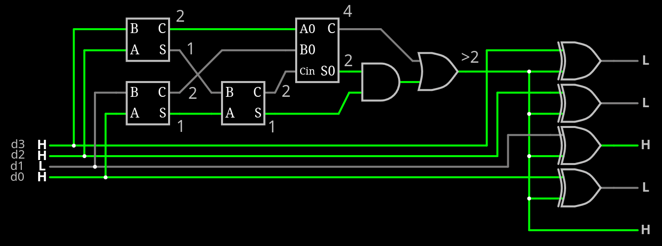
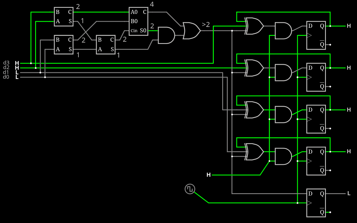
- The 18-bit word is cut in 2 halves that get independently popcounted and inverted: it's "TMPI" (Transition-Minimised Parallel Interface) or "Bus Inversion" (in DDR4/DDR5 terminology)
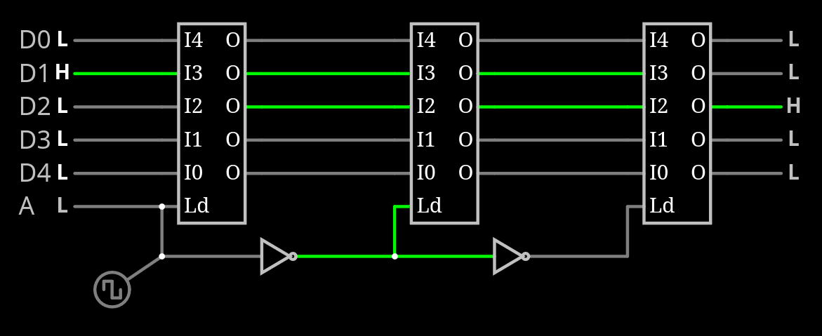
- Both 10-bit results are multiplexed into a 5-bit channel with NRZ/NRZI over 4 cycles
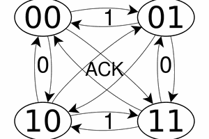
- The 4 cycles are clocked by 2 clock signals in quadrature. The phase (0-180°) transmits one additional bit per transaction, signalling the type of transaction (data or control/config)
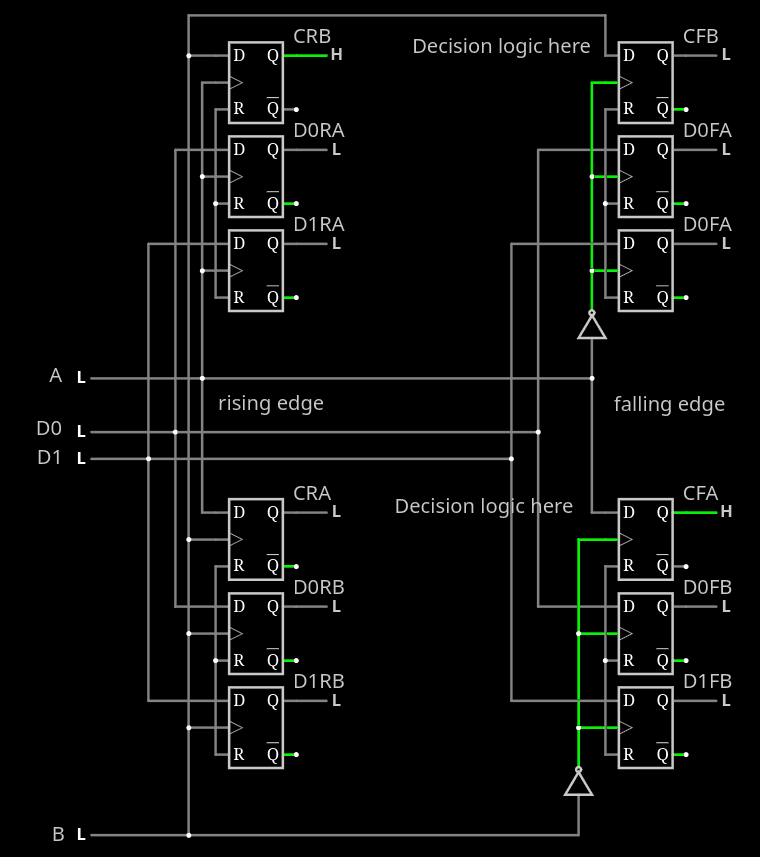
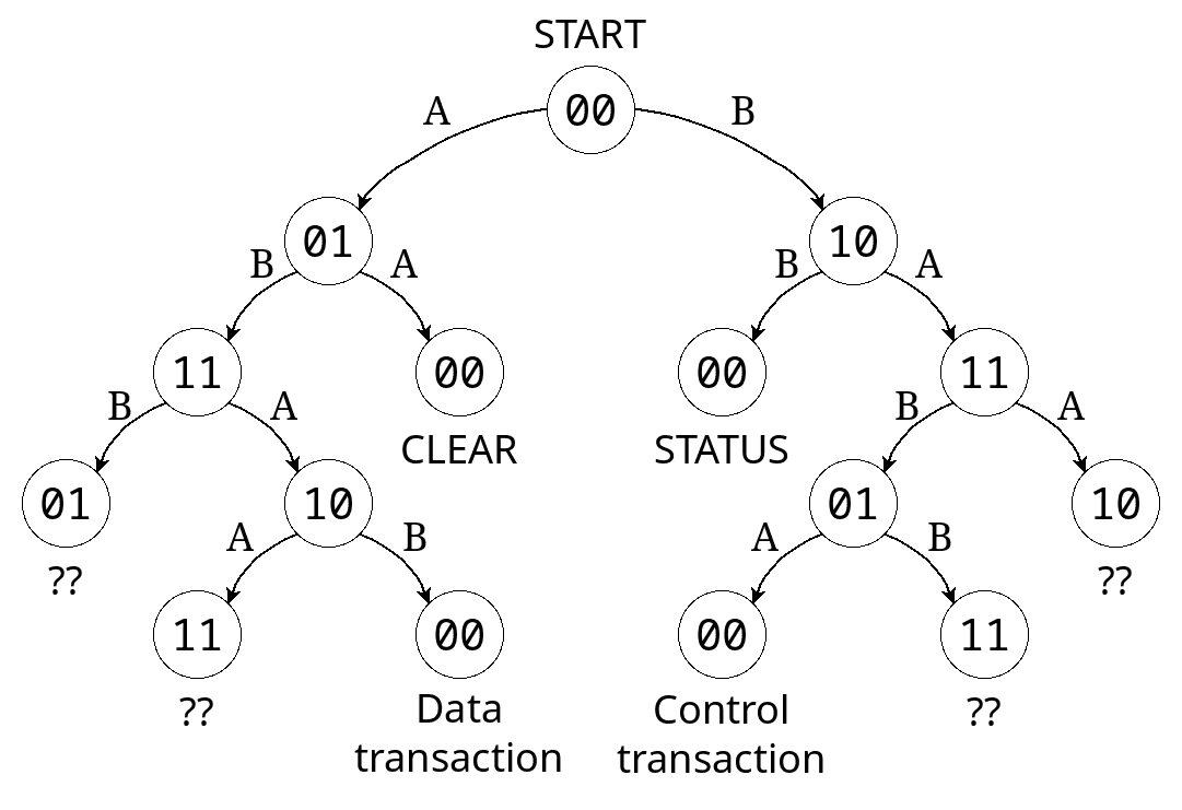
- The clock signals can also work in other ways, opening the door to a sophisticated state machine. For example, a certain "aborted" clock sequence can reset the link and clear the NRZ/I register. Other patterns can trigger other behaviours.
So here you have the 7 wires. Normally you want two channels, one per direction, for a total of 14 wires. And you can create your own protocol over this.
This interface is not limited to networking and could be repurposed for other types of inter-chip communication, passing messages from IC to IC on a PCB, because there is inherent support for a control channel and relaxed clocking requirements. For example I hope to use this to connect high-bandwidth designs implemented on future Tiny Tapeout projects.
-o-O-0-O-o-
Logs:
1. Clocking
2. Data latching
3. Pin layout
4. Transition density
5. 16-bit mode
6. YGMII7-16
7. .
8. .
9. .
10. .
11. .
12. .
13. .
14. .
15. .
16. .
.
.

 zpekic
 Jac Goudsmit