 Yann Guidon / YGDES
Sending/generating any type of data is trivial. Receiving is hard, and the higher the frequency, the harder it gets.
In the case of YGMII, data are "source clocked" which means the stream is more or less asynchronous to the receiver. A proper FIFO is required but that's not the real problem. Missing a word that arrives too late for the PHY ? => insert an IDLE symbol and that's it.
Now getting the clock is something else and it's asynchronous. Adding a PLL will only increase the problems of jitter (on a wire or system-wise). And then you have to demux and process the FSM.
One thing helps though : there are an even number of edges on each clock wire A and B to complete a transaction. So each transaction is made of at least 2×5 bits. The data transaction with 20 bits is one case among others, even the CLEAR or STATUS transactions need 2 cycles and carry 10 bits of payload.
This means that for each clock signal there is a pair of edge-triggers D latches, each triggered by a different edge polarity. And the FSM can be built from this distributed collection of four rows of DFFs.
.
The following example shows only 2 of the 5 bits for clarity, and illustrates the fundamental idea/principle:
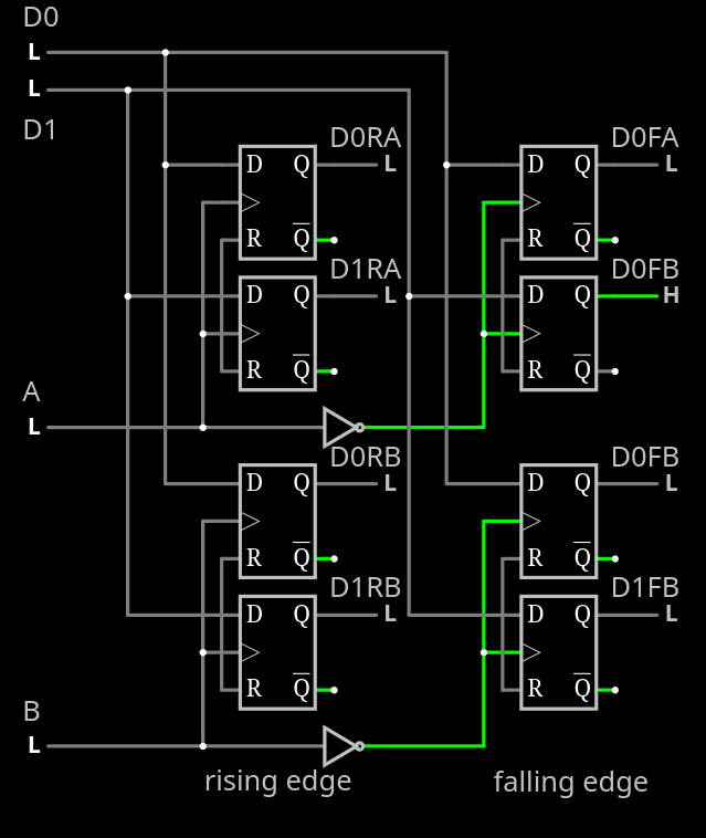
This system is inherently asynchronous and in the end requires resynchronisation with the host/receiver, but this can be done with a handshake on larger words, at a slower frequency. This flexibility enables faster transmission rates and some small amount of jitter between the emitter's clock and the receiver's.
.
Note that each DFF is a pair of transparent latches, so 2 DFF clocked by opposite fronts could be merged. This leads to a "triple latch" structure to reduce redundancy and footprint:
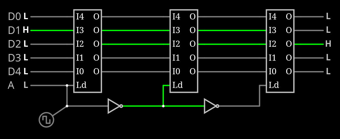
But this optimisation will come later. And it's only the beginning because the clock-controlled FSM should run in real time, updated at each incoming front. This leads to a "distributed FSM" where each of the 4 zones is activated in turn, and updates its state by reading the other's clock signal value and the other states.
Extending the binary decision tree from the last log, we add the criterion of parity and we find that the FSM can return to the "IDLE"/End of transaction on the falling edges, so every other row of decision.
- CLEAR and STATUS can be reached after 2 transitions, of the same signal, with the other never moving.
- DATA and CONTROL are reached after 4 transitions
This means that the FSM logic can be concentrated at the inputs of the falling edge registers.
And when the transaction is complete, the temporary status stored in the rising edge registers is cleared. Or something similar. So a new transaction can be decoded again.
The result:
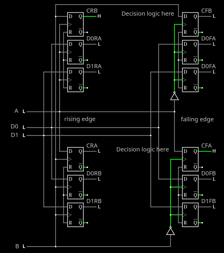
Each rising edge layer registers the state of the opposite clock, and from there the falling edge can determine which type of transaction ends.
Discussions
Become a Hackaday.io Member
Create an account to leave a comment. Already have an account? Log In.