 Yann Guidon / YGDES
The interface uses 2 clock signals: this provides a reasonable EMI reduction and it also extend the protocol.
The 2 clock wires are required to encode the 4 edges of a full transaction in normal/usual mode. The signals follows the traditional Gray counting sequence:
00
01
11
10
and the whole transaction is ended when both signals are back to 0.
Swapping the sigals corresponds to counting in reverse:
00
10
11
01
This signals that the transaction contains a control or status word.
There is a rule that only one wire can change at a time and each front updates the state of a sort of FSM.
Naming the clock signals A and B, we get a sequence of these letters and the sequence ends when the number of As and Bs are both even.
Thus we get these 4 basic sequences:
AA : reset AC register  (set to current value ?)
BB : Update link status (9 bits?)
ABAB : Data transaction (18 bits)
BABA : Control transaction
Another way to visualise is with a binary decision tree:
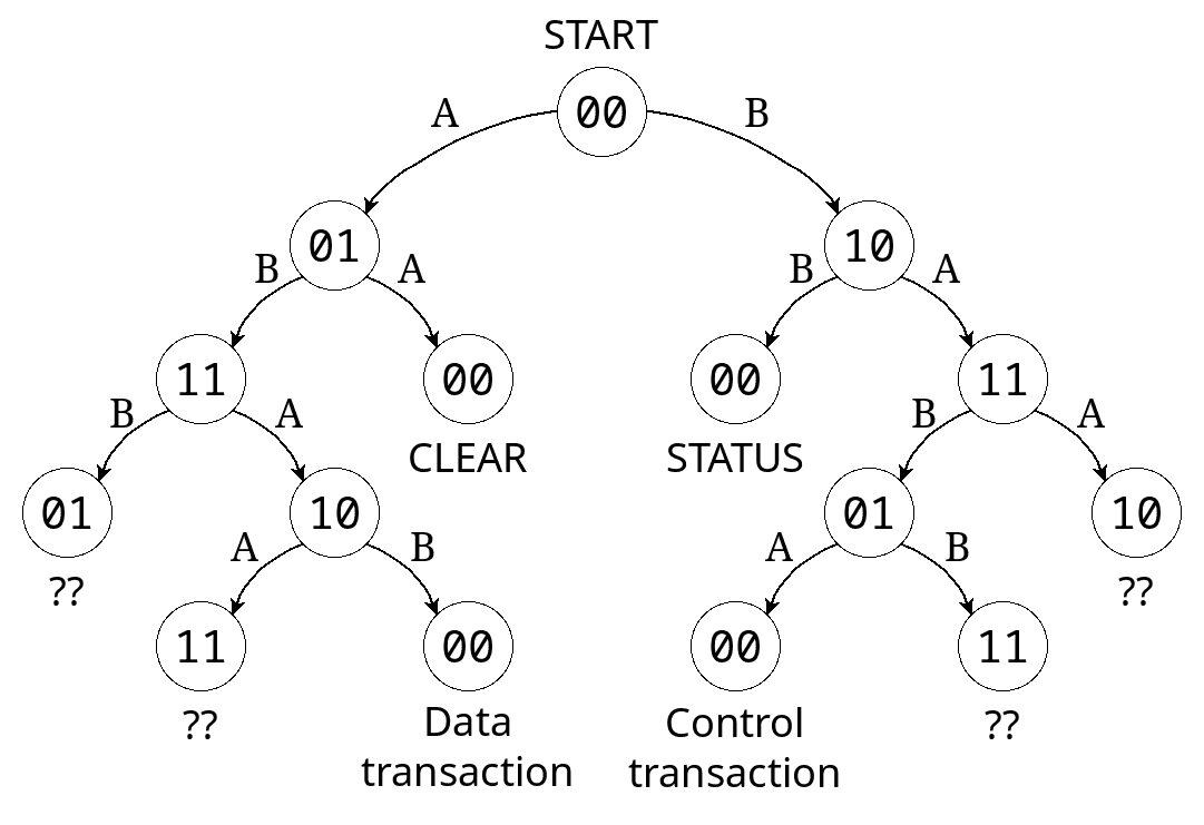
You get the idea: the protocol is extensible and we start with a few good cases that are easy to use without too much complexity.
Discussions
Become a Hackaday.io Member
Create an account to leave a comment. Already have an account? Log In.