 Yann Guidon / YGDES
The scrambler works but the last log 105. gPEAC: the circuit (2) found a problem with the descrambler: there can not be two carry inputs in the accumulation (decumulation ?) phase.
However this is an issue IF I try to follow the mantra of "have only adders". The second phase (adjust modulo) IS actually a subtraction ! So the descrambler can use a subtracter during both phase. It's time to update the diagram and the algo. But this would work only if the subtracter is not made of an adder with inverted carry input.
For faster execution but mostly for easier implementation (because VHDL does not permit boolean operations), a C version seems required.
-------------------
The port to C is doing well, at least for the scrambler.
Tne descrambler code is in the same bloc so the registers must have different names, I have chosen A, B, C, D and T.
Log 34. PEAC treillis helps for the init values again.
From the scrambler side:
- Do0 = Di0 + InitX
- Do1 = Di1 + InitX + InitY
- Do2 = Di2 + Do0 + InitX + InitY
= Di2 + Di0 + 2×InitX + InitY
From the descrambler side:
- Di0 = Do0 - InitX
- Di1 = Do1 - (InitX + InitY)
- Di2 = Do2 - (Do0 + InitX + InitY)
= Do2 - (Di0 + 2×InitX + InitY)
==>
A not initialised, B = INIT_X, T = INIT_Y.
Now, gPEAC18_codec.c works:
#include <stdint.h>
#include <inttypes.h>
#include <stdio.h>

#define MODULUS (258114)
#define ADJUST  (262144-MODULUS)
#define INIT_X   (56247) // "01101101110110111"
#define INIT_Y  (111981) // "11011010101101101"

int main() {
  uint64_t cycles = 0;
  int Msg = 12345,
   // scrambler
      X = INIT_X,
      Y = INIT_Y,
      X2, X3, Y2, V=0, W=0,
   // descrambler
      A, B = INIT_Y,
      B2, C=0, D=0,
      T = INIT_X;

  for (int j=0; j<670; j++) {
    for (int i=0; i<100000000; i++) {
/////////////////////////////// Scrambler
      // phase0 : accumulation/Fibonacci on 19 bits + carry in
      X2 = Msg + Y + V;
      Y2 =   X + Y + W;
      X = X2;
      Y = Y2;

      // phase1 : modulo
      X3 = X2 + ADJUST;
      Y2 = Y  + ADJUST;

      V = X3 >> 18;
      W = Y2 >> 18;

      if (V) { X = X3 & 262143; }
      if (W) { Y = Y2 & 262143; }

/////////////////////////////// Descrambling
      if (X >= MODULUS) {
        printf("\n   X OVERFLOW !!\n");
        goto the_end;
      }

      // phase0 : decumulation
      A = X - (C + B);
      B = T +  D + B ;
      T = X;

      // phase1 : modulo
      C = (A >> 18) & 1;
      if (C) { A = (A - ADJUST)& 262143; }

      B2 = B + ADJUST;
      D =  B2 >> 18;
      if (D) { B = B2 & 262143; }

      cycles++;
      if (X == INIT_X) {
        if (Y == INIT_Y) {
          goto the_end;
        }
      }
      if (A != Msg) {
        printf("\n A=%05X != Msg !\n", A);
        goto the_end;
      }
    }
    printf("%" PRId64 ": %05X  %05X\n", cycles, X, Y);
  }
the_end:
  printf("\n%" PRId64 ": X=%05X  Y=%05X\n", cycles, X, Y);
  return 0;
}
The subtraction expression can be modified to an addition:
A = X - (C + B);
  = X + 1+ ~(C + B);
  = X + ~B + (C^1);
so B and C are simply booleanly complemented and the carry input is simplified.
Pfew.
The diagram below shows the subtle changes with the handling of the carry signals:
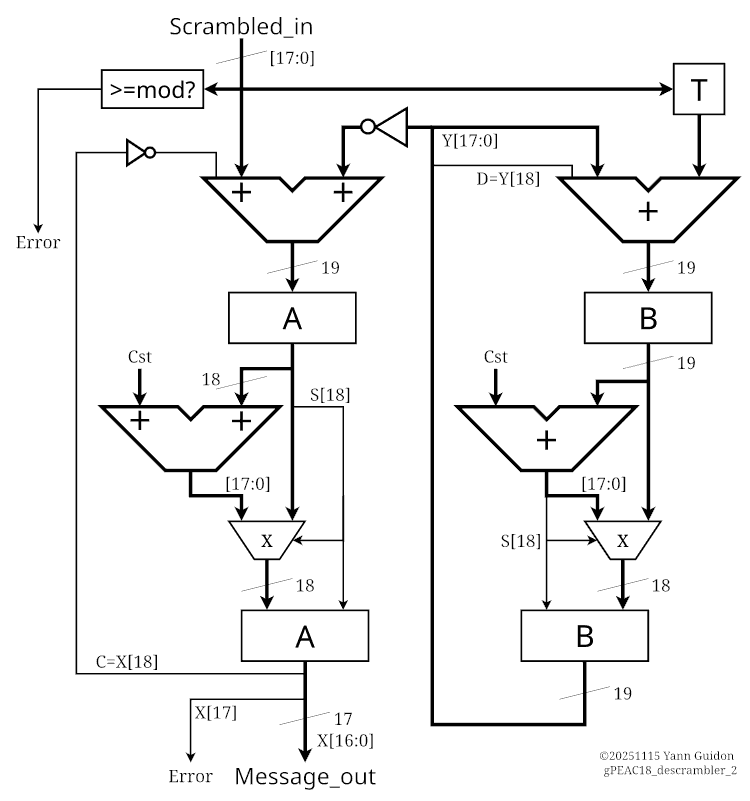
.
Now the circuit must be folded back into a single pair of adders and 2 cycles, hence more MUX.
The easiest place to start is the B pipeline which is almost a copy of the scrambler, except with an additional T register. The adder inputs are easy to allocate : one addend is B (with or without carry in), the other is MUX(T, Cst).
The left side (message decumulating) is more peculiar. The operands of the adder are
- (Scrambled_In, Cst) + ( /Y, A)
- (Scrambled_In, A) + ( /Y, Cst)
There is no advantage to either, since there is only one constant.
And here is the result:
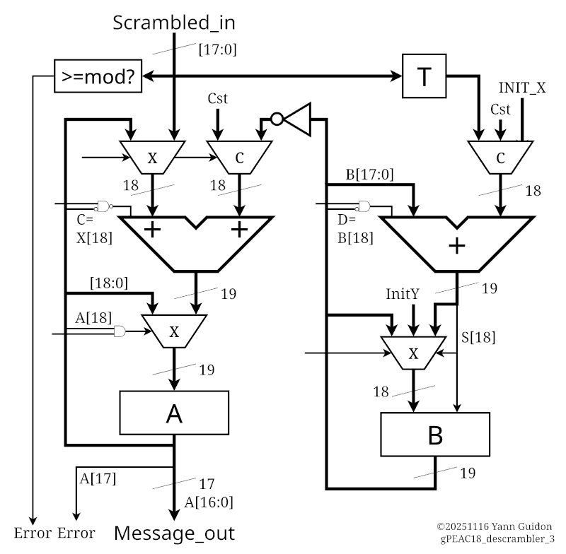
Not represented : Reset and Phase signals.
.
Discussions
Become a Hackaday.io Member
Create an account to leave a comment. Already have an account? Log In.