 Yann Guidon / YGDES
The architecture is settled and "just needs to be coded".
The C code is pretty simple, one variable and 3 lines are added per peer (ResX2 & ResA2).
// Decrambler
int Message_in, OpM, OpY2, ResX, X, Y, CX, CXin,
   CXout, Scrambled_out, ResX2;

void cycle_scrambler() {
  OpM = Message_in;
  OpY2 = Y;
  CXin = CX;
  ResX = OpM + OpY2 + CXin;
  X = ResX & MASK18;
  ResX2 = ResX + ADJUST;
  CX = (ResX | ResX2) >> 18;
  if (CX)
    X = ResX2 & MASK18;
  Scrambled_out = X;
}


// Decrambler
int Scrambled_in, OpM2, OpB2, B, A, ResA, CA, CAin,
    CAout, Message_out, error, ResA2;

void cycle_descrambler() {
  OpM2 = Scrambled_in;
  OpB2 = (~B) & MASK18;
  CAin = CA;
  ResA = OpM2 + OpB2 + CAin;
  A  = ResA & MASK18;
  ResA2 = ResA + ADJUST;
  CA = (ResA | ResA2) >> 18;
  if (CA)
    A = ResA2 & MASK18;
  Message_out = A & MASK17;
  error = (A >> 17 ) & 1;
}
Aaaand it doesn't work.
As usual the encoder is fine but the decoder is a hot jacuzzi of "what's going on ?"
It took a while (again) but this version finally works:
void cycle_descrambler() {
  OpM2 = Scrambled_in;
  OpB2 = (~B)&MASK19;        /// <=== !!!
  CAin = CA^1;               /// <=== !!!
  ResA = OpM2 + OpB2 + CAin;
  A  = ResA & MASK18;
  ResA2 = A + MODULUS;       /// <=== !!!
  CA = ((ResA >> 18) &1);    /// <=== !!!!!!!!
  if (CA)
    A = ResA2 & MASK18;
  Message_out = A & MASK17;
  error = (A >> 17 ) & 1;
}
It's still quite unconventional and hard to grasp so a diagram is required.
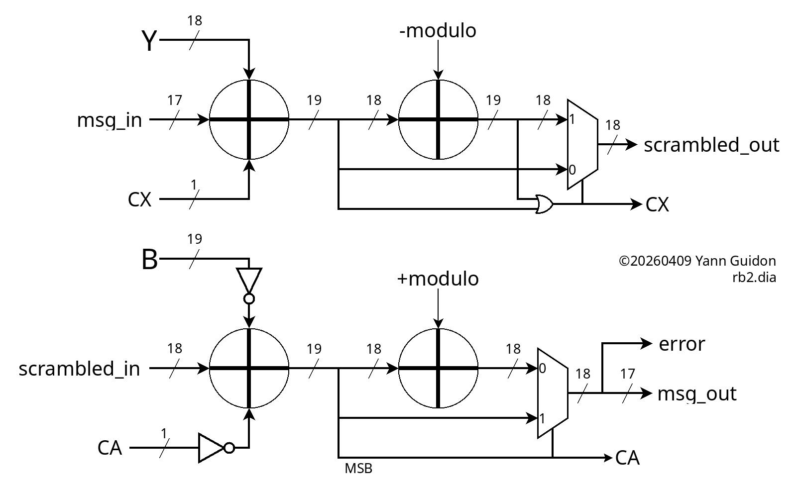
The key detail is that the descrambler is not a modular addition, unlike the scrambler. Logically it's a modular subtraction and this changes a lot of non-obvious details. In particular:
- the scrambler works in the unsigned, positive range, from 0 to 2×mod, hence the OR to detect overflow,
- the descrambler, starting from range 0 to mod, subtracts another value from 0 to mod, so the output range goes from -mod to +mod, hence the sign bit is the MSB from the first "inverted addition" and no OR this time.
The C code generates a longer list of test vectors, such that the thin slice of invalid values (from modulo to 262144) get corrected:
[   1234,  225196],
[  38650,    4498],
[  76066,   41915],
[ 113482,   79331],
[  19826,  243789],
[  57242,   23090],
[  94658,   60507],
[   1002,  224965],
[  38418,    4266],
[  75834,   41683],
[ 113250,   79099],
[  19594,  243557],
[  57010,   22858],
[  94426,   60275],
[    770,  224733],
[  38186,    4034],
[  75602,   41451],
[ 113018,   78867],
[  19362,  243325],
[  56778,   22626],
[  94194,   60043],
[    538,  224501],
[  37954,    3802],
[  75370,   41219],
[ 112786,   78635],
[  19130,  243093],
[  56546,   22394],
[  93962,   59811],
[    306,  224269],
[  37722,    3570],
[  75138,   40987],
[ 112554,   78403],
[  18898,  242861],
[  56314,   22162],
[  93730,   59579],
[     74,  224037],
[  37490,    3338],
[  74906,   40755],
[ 112322,   78171],
[  18666,  242629],
[  56082,   21930],
[  93498,   59347],
[ 130914,   96763],
[  37258,    3107],
[  74674,   40523],
[ 112090,   77939],
[  18434,  242397],
[  55850,   21698],
[  93266,   59115],
[ 130682,   96531],
[  37026,    2875],
[  74442,   40291],
[ 111858,   77707],
[  18202,  242165],
[  55618,   21466],
[  93034,   58883],
[ 130450,   96299],
[  36794,    2643],
[  74210,   40059],
[ 111626,   77475],
[  17970,  241933],
[  55386,   21234],
[  92802,   58651],
[ 130218,   96067],
[  36562,    2411],
[  73978,   39827],
[ 111394,   77243],
[  17738,  241701],
[  55154,   21002],
[  92570,   58419],
[ 129986,   95835],
[  36330,    2179],
[  73746,   39595],
[ 111162,   77011],
[  17506,  241469],
[  54922,   20770],
[  92338,   58187],
[ 129754,   95603],
[  36098,    1947],
[  73514,   39363],
[ 110930,   76779],
[  17274,  241237],
[  54690,   20538],
[  92106,   57955],
[ 129522,   95371],
[  35866,    1715],
[  73282,   39131],
[ 110698,   76547],
[  17042,  241005],
[  54458,   20306],
[  91874,   57723],
[ 129290,   95139],
[  35634,    1483],
[  73050,   38899],
[ 110466,   76315],
[  16810,  240773],
[  54226,   20074],
[  91642,   57491],
[ 129058,   94907],
[  35402,    1251]
The VHDL code is almost a formality at this point, and it was pretty smooth this time. It still looks messy because of the use of signals instead of variables (to ease comparisons with gtkwave) but that's merely a formatting detail.
    procedure init_scrambler is
    begin
      X <= INIT_X;  -- does not matter yet
      Y <= INIT_Y;
      CX<= '0';
      wait for 1 ns;
    end procedure;

    procedure cycle_scrambler is
    begin
      wait for 1 ns;

      OpM <= '0' & Message_in; -- pad MSB
      OpY2 <= Y;
      CXin <= CX;
      wait for 1 ns;

      ResX <= unsigned('0' & OpM  & '1' )
            + unsigned('0' & OpY2 & CXin);
      wait for 1 ns;

      CXout <= std_ulogic(ResX(19));
      X <= std_ulogic_vector(ResX(18 downto 1));
      wait for 1 ns;

      ResX2 <= unsigned('0' & ResX(18 downto 1))
             + unsigned('0' & ADJUST);  -- no carry in here
      wait for 1 ns;

      CXout2 <= std_ulogic(ResX2(18));
      wait for 1 ns;

      CX <= CXout or CXout2;
      wait for 1 ns;

      if CX /= '0' then
        X <= std_ulogic_vector(ResX2(17 downto 0));
        wait for 1 ns;
      end if;

      Scrambled_out <= X;
      wait for 1 ns;
    end procedure;

---------------------------------------------
    procedure init_descrambler is
    begin
      --A <= INIT_X;  -- does not matter yet
      B <= INIT_Y;
      CA<= '0';
    end procedure;

    procedure cycle_descrambler is
    begin
      wait for 1 ns;

      OpM2 <= Scrambled_in;
      OpB2 <= not B;
      CAin <= not CA;
      wait for 1 ns;

      ResA <= unsigned('0' & OpM2 & '1' )
            + unsigned('1' & OpB2 & CAin); -- OpB2 is sign-extended
      wait for 1 ns;

      CAout <= std_ulogic(ResA(19));
      A <= std_ulogic_vector(ResA(18 downto 1));
      wait for 1 ns;

      if CAout /= '0' then
        ResA2 <= ResA(18 downto 1)
               + unsigned(MODULO);  -- no carry in or out here
        wait for 1 ns;
        A <= std_ulogic_vector(ResA2);
        wait for 1 ns;
      end if;

      CA <= CAout;
      Message_out <= A(16 downto 0);
      error <= A(17);
      wait for 1 ns;
    end procedure;
And a lot of moving data around in various aliases, too, because I planned a 2-cycle circuit with MUXes but there are fewer intermediary results now. And it passes 100 test vectors, I'll cleanup later.
One problem remains: ResA adds 19 bits and not 18 so I must find how to drop these constant bits.
It's only a matter of inverting the carry signal then:
void init_descrambler() {
  A=-1;
  B=INIT_Y;
  CA=1;     // <==
}

void cycle_descrambler() {
  OpM2 = Scrambled_in;
  OpB2 = (~B)&MASK18;         // <==
  CAin = CA;                  // <==
  ResA = OpM2 + CAin + OpB2;
  A  = ResA & MASK18;
  ResA2 = A + MODULUS;
  CA = (ResA >> 18) & 1;
  if (!CA)                    // <==
    A = ResA2 & MASK18;
  Message_out = A & MASK17;
  error = (A >> 17 ) & 1;
}
And the VHDL follows:
    procedure init_descrambler is
    begin
      --A <= INIT_X;  -- does not matter yet
      B <= INIT_Y;
      CA<= '1';
    end procedure;

    procedure cycle_descrambler is
    begin
      wait for 1 ns;

      OpM2 <= Scrambled_in;
      OpB2 <= not B;
      CAin <= CA;
      wait for 1 ns;

      ResA <= unsigned('0' & OpM2 & '1' )
            + unsigned('0' & OpB2 & CAin);
      wait for 1 ns;

      CAout <= std_ulogic(ResA(19));
      A <= std_ulogic_vector(ResA(18 downto 1));
      wait for 1 ns;

      if CAout /= '1' then
        ResA2 <= ResA(18 downto 1)
               + unsigned(MODULO);  -- no carry in or out here
        wait for 1 ns;
        A <= std_ulogic_vector(ResA2);
        wait for 1 ns;
      end if;

      CA <= CAout;
      Message_out <= A(16 downto 0);
      error <= A(17);
      wait for 1 ns;
    end procedure;
And after so much good preparation, the Verilog compiles and simulates on first try (or so).
.
Reducing the speed back to 10ns (easier/faster convergence), we get https://github.com/ygdes/miniMAC_IHP/actions/runs/24197988265
I think the 100MHz clock still gives a wide margin. I'll see later when synthesis crumbles with a full circuit.
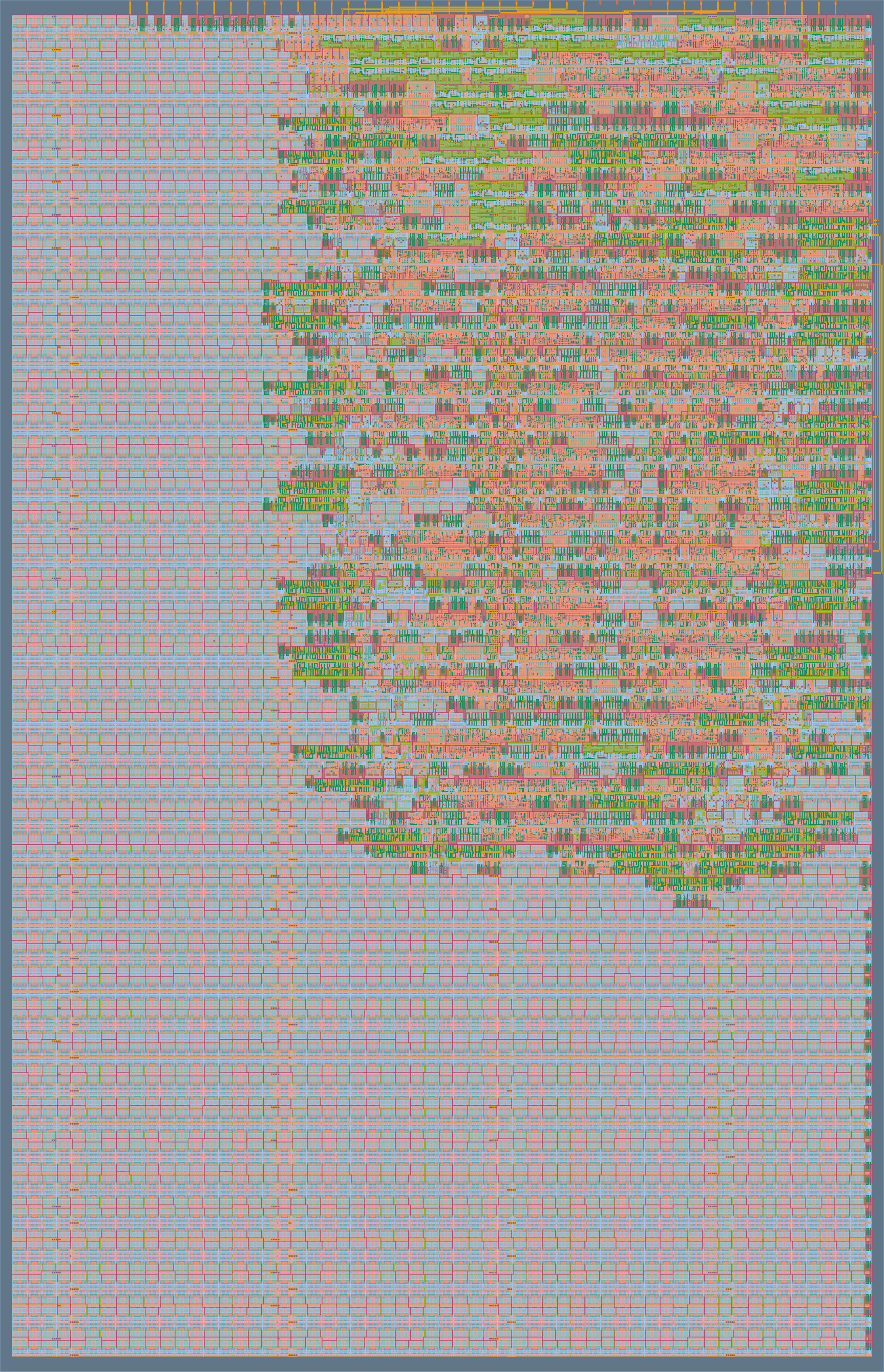
The Hammer18 circuits and all the registers are included. Routing looks nice, with moderate contention on the top layers. There is more than ample margin to add the "Y" path !
Discussions
Become a Hackaday.io Member
Create an account to leave a comment. Already have an account? Log In.