Electronics
As I can't make up my mind, there are two designs of the PCB: The dramatic duckJAWS, a Jaws-style shark (sea-monster?) nibbling at the tail of the duck. And the more mellow duckBATH, a bubbly bathtub for the duck to float on.
Both PCBs share similar circuits and the same firmware. Both support a common anode RGB LED, or a 2-legged "UV" LED. duckJAWS also features side-lit red LEDs to add an ominous glow to the shark's teeth.
The MCU on the SAO is a CH32V003, and its programming pin is exposed on GPIO1.
The SAO features a 3.3V boost converter. This ensures full LED brightness even when the SAO runs off unregulated batteries (like for example on the 2023 Supercon badge). 3.3V limits the brightness with a UV LED, so I might increase the voltage on a future revision.
Two solder jumpers allow to configure the SAO to four different I2C addresses.
Control
Color and animation parameters can be controlled over I2C. When happy with the reconfigured rubber duck, the settings can be stored as new power-on default via another I2C command.
The documentation for the I2C registers is stored on the SAO and can be read over I2C. There's also an Easter-egg to reward the I2C curious.
In addition to I2C, the SAO also supports the WS2812 protocol on GPIO2, turning the rubber duck into a NeoPixel.
See GitHub for more detailed documentation of the I2C registers, including a few examples.
Assembly
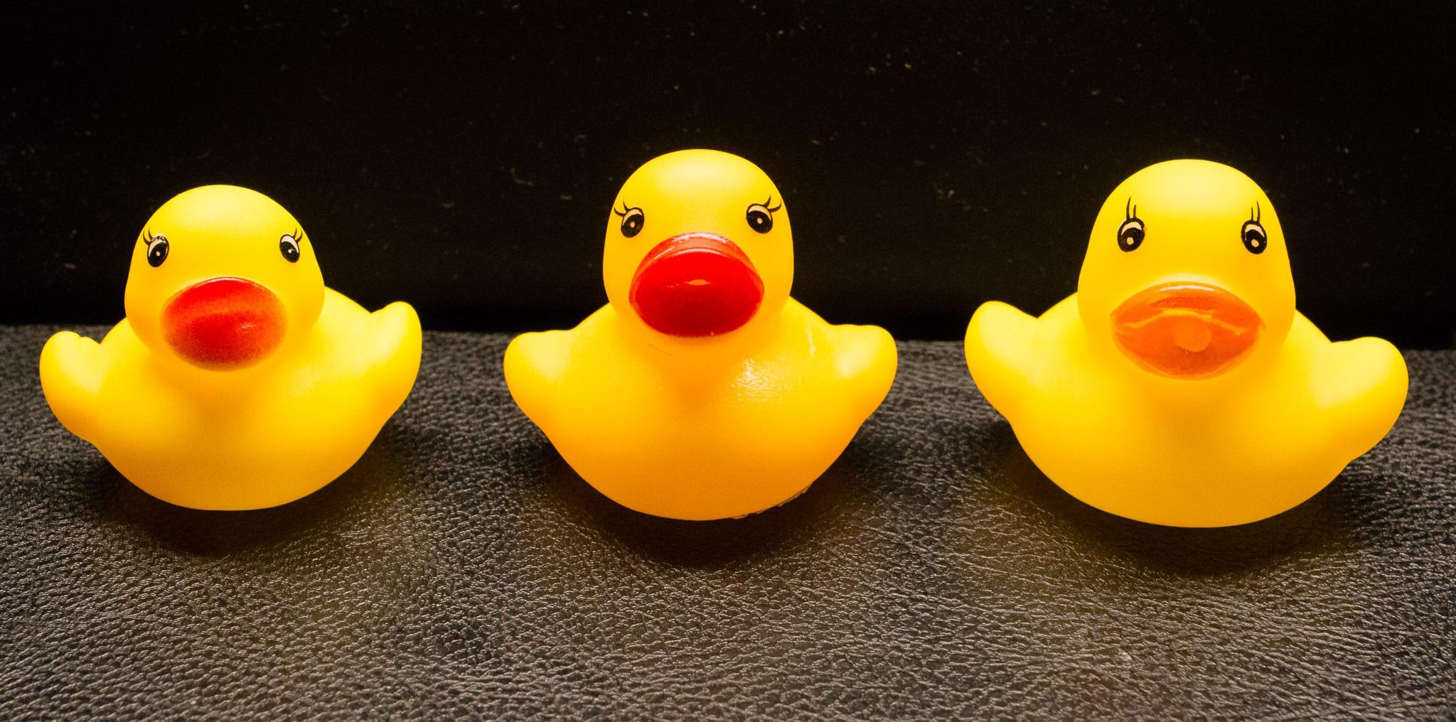
Obviously, manufacturing of a widget with genuine rubber ducks poses a bit of a DFM challenge.
The plan is, to distribute partially assembled duckGLOW SAOs in kit form:
- 1x diffused LED
- 1x unadultered rubber duck
- 1x PCB with pre-assembled SMT parts
To mount the duck to the SAO, first the legs of the LED are bent 90 degree. The LED is then hot-glued to the bottom of the rubber duck. This assembly is then soldered to the SAO.
The prospective duck parent (or conference host) will have to provide solder and (hot-)glue.
 Adrian Studer



 Gerben
 Sam Ettinger
 Mirko
Mirko
 Martin Held
video: https://www.youtube.com/watch?v=yjSSQkx-x7U