Greetings everyone and welcome back, This is the Pocket Synth, a do-it-yourself compact Formfactor synth constructed with 3D-printed components and Seeed's XIAO expansion board.
The core of this project is the Seeed XIAO ESP32 S3 microcontroller board, which is placed in a 3D printed frame along with an XIAO expansion board and a button board. Because of its built-in battery, this solution is both convenient and completely portable.
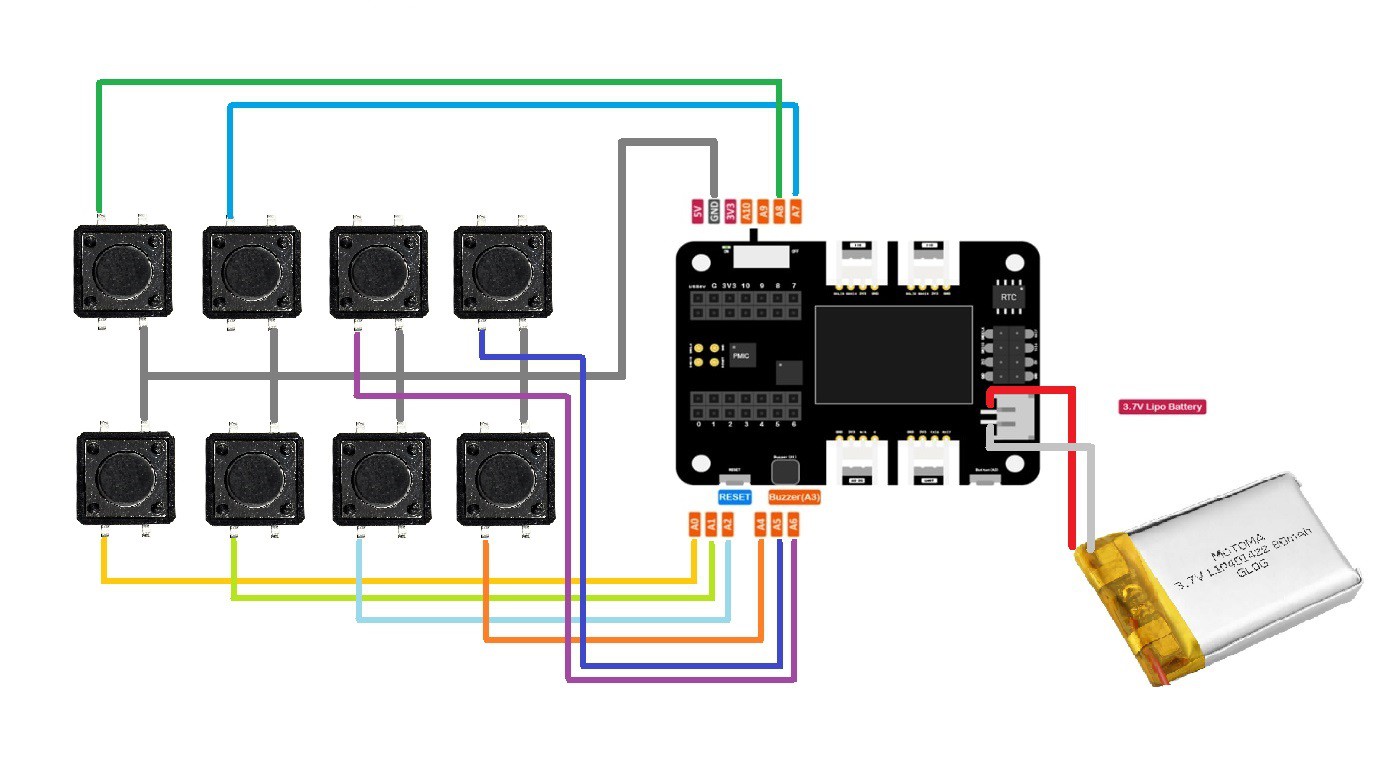
This project uses eight buttons, and the buzzer on the XAIO expansion board is utilized to output the synth sound.
Details
Design
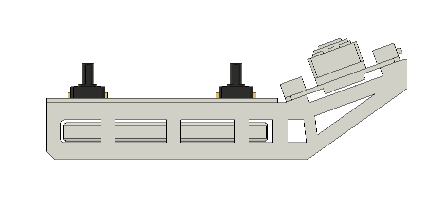
In order to design this project, we first imported the 3D model of the XIAO expansion board, button board, and 3.7V battery. We then arranged these components so that we only needed to model the two frames that connect the expansion board and button board and maintain the battery lock in place.
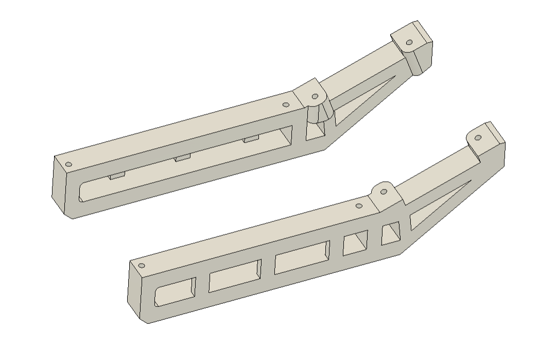
Two frames with mounting holes for the button board and expansion board were modeled.
We exported the frame mesh files and 3D printed them using Black PLA with a 0.4mm nozzle with 0.2mm layer height.
XIAO ESP32 S3 and XIAO Expansion Board
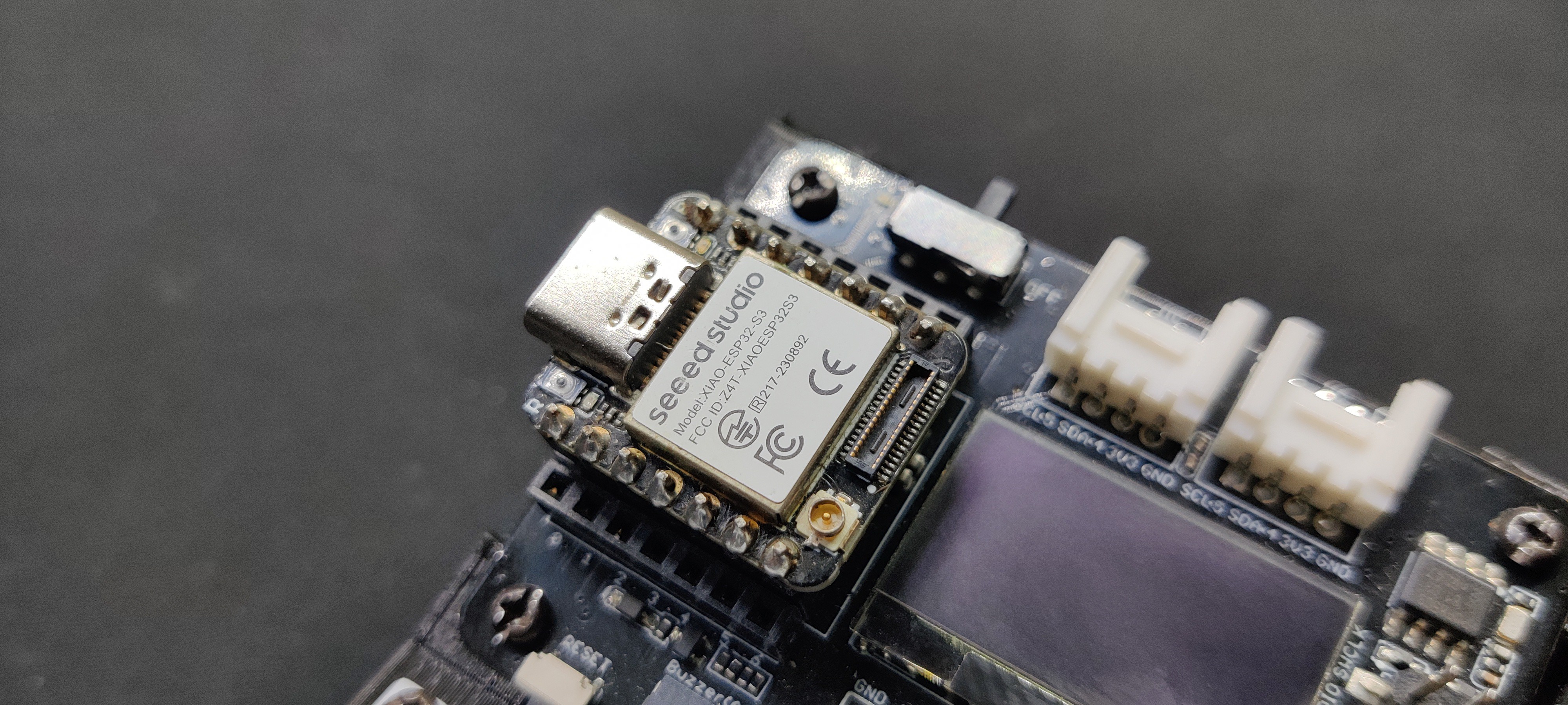
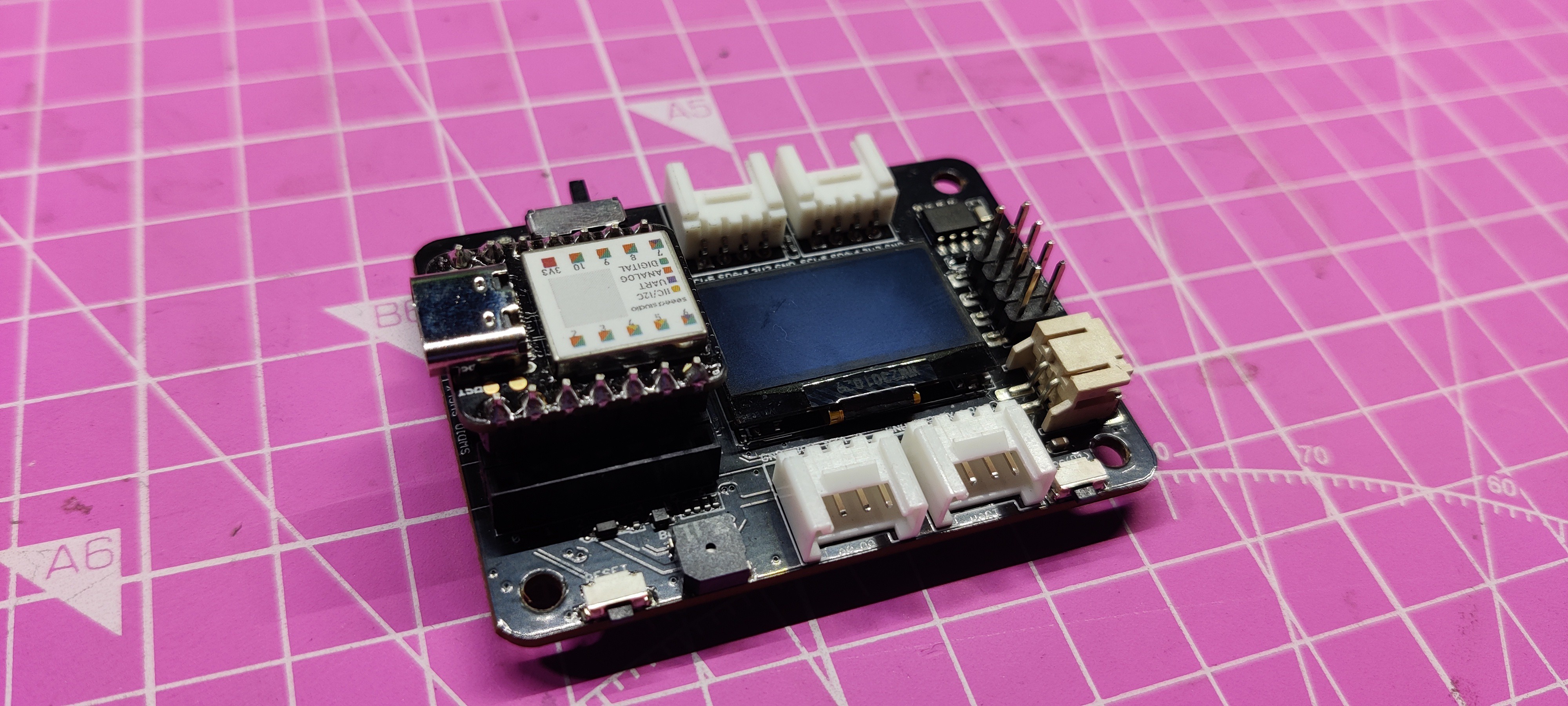
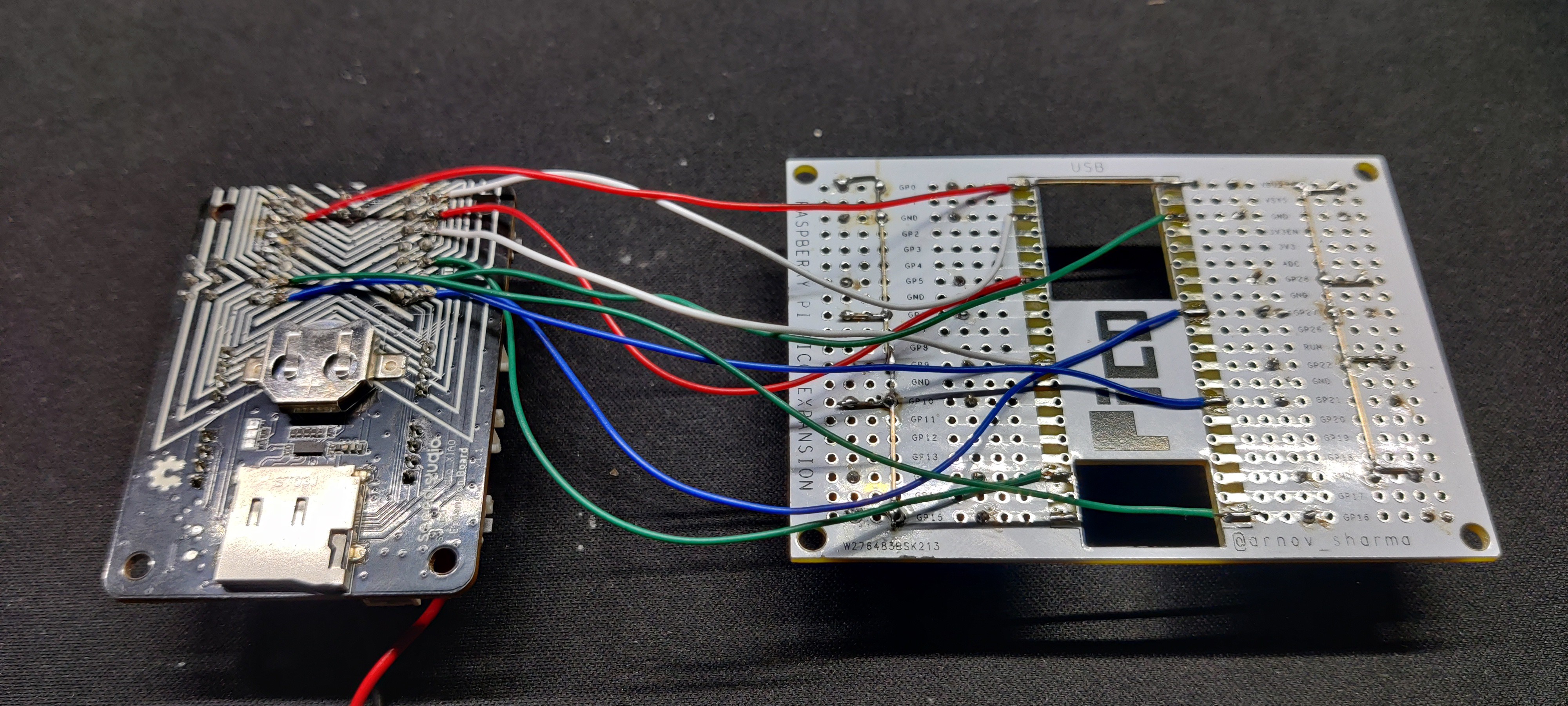
We're using the XIAO ESP32 S3 Development Board, which, paired with the XIAO extension board manufactured by Seeed Studio, is the heart of this project.
The ESP32S3 32-bit dual-core Xtensa processor chip, which runs at up to 240 MHz, is integrated inside the XIAO ESP32 S3. It supports Arduino and MicroPython and has several development interfaces.
It supports 2.4GHz Wi-Fi and BLE dual, has 8 MB of PSRAM and 8 MB of FLASH, and has an SD card connector for external 32 GB FAT memory.
The expansion board's OLED screen and the onboard buzzer, which is coupled to the XIAO's I/O Pin D3, are being used in this project.
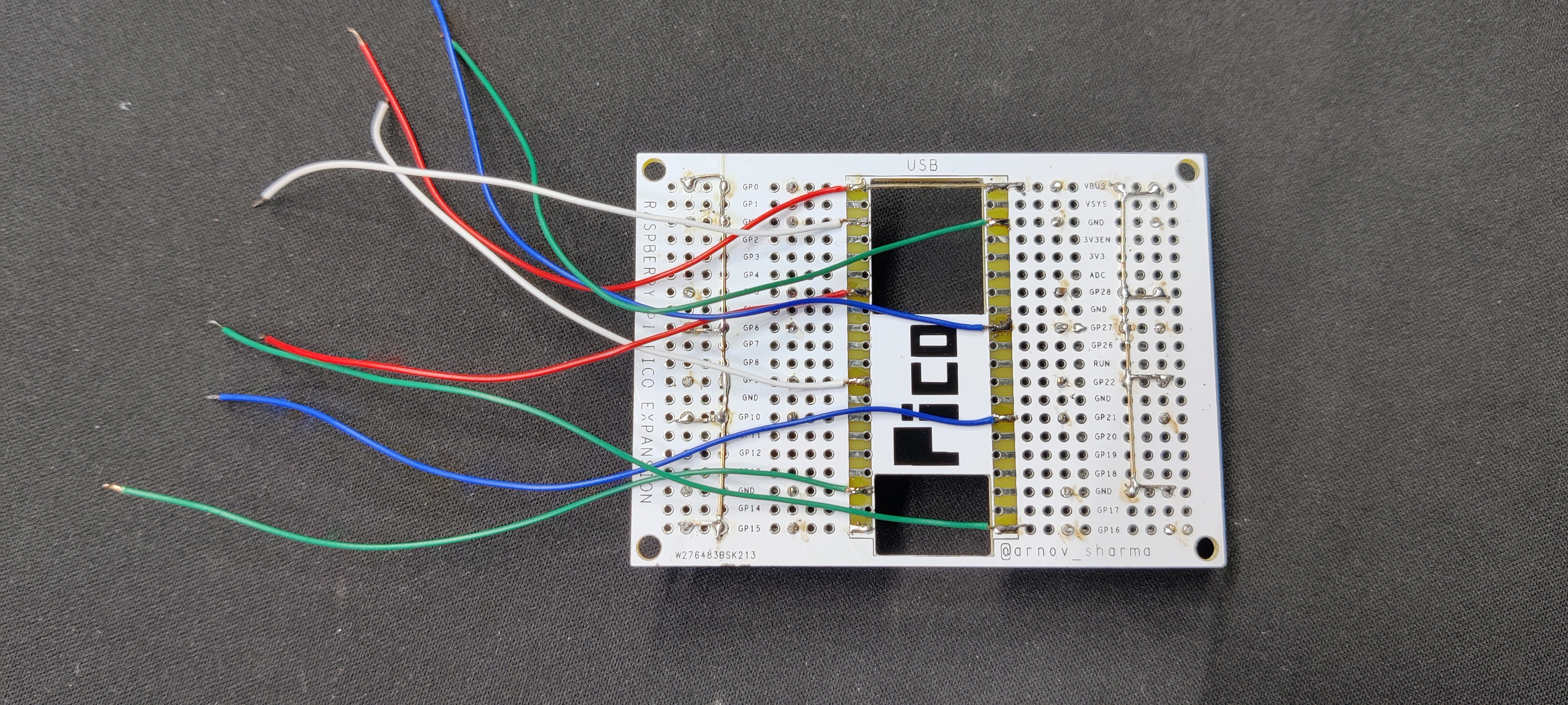
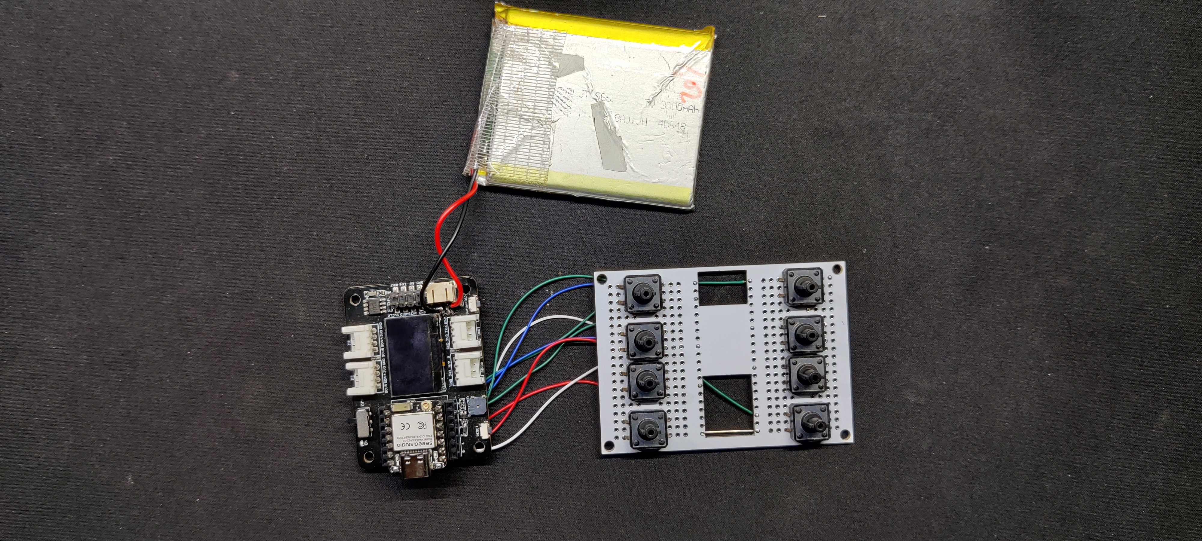
Furthermore, wires will be used to connect the XIAO extension board to a custom-built button board.
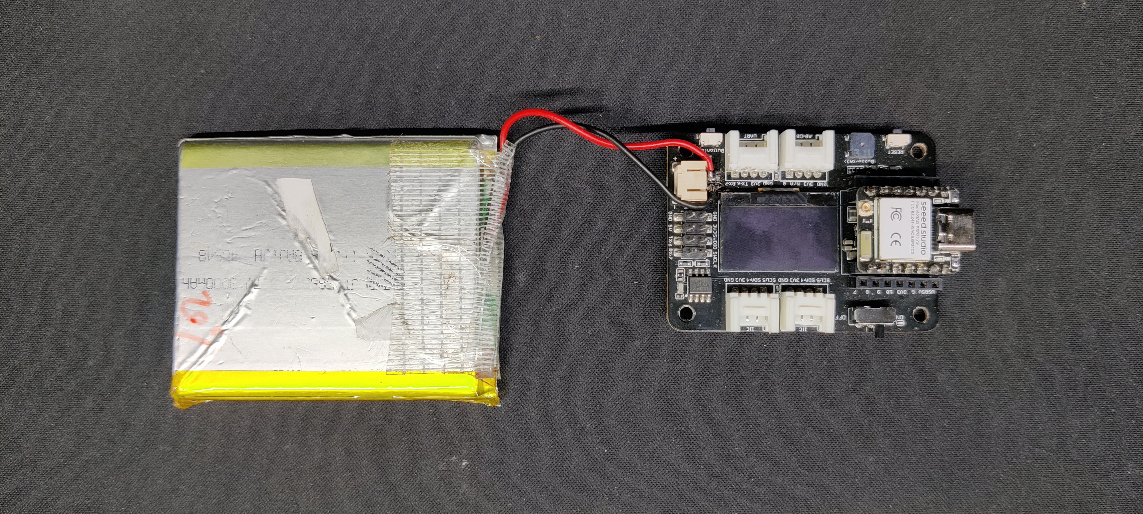
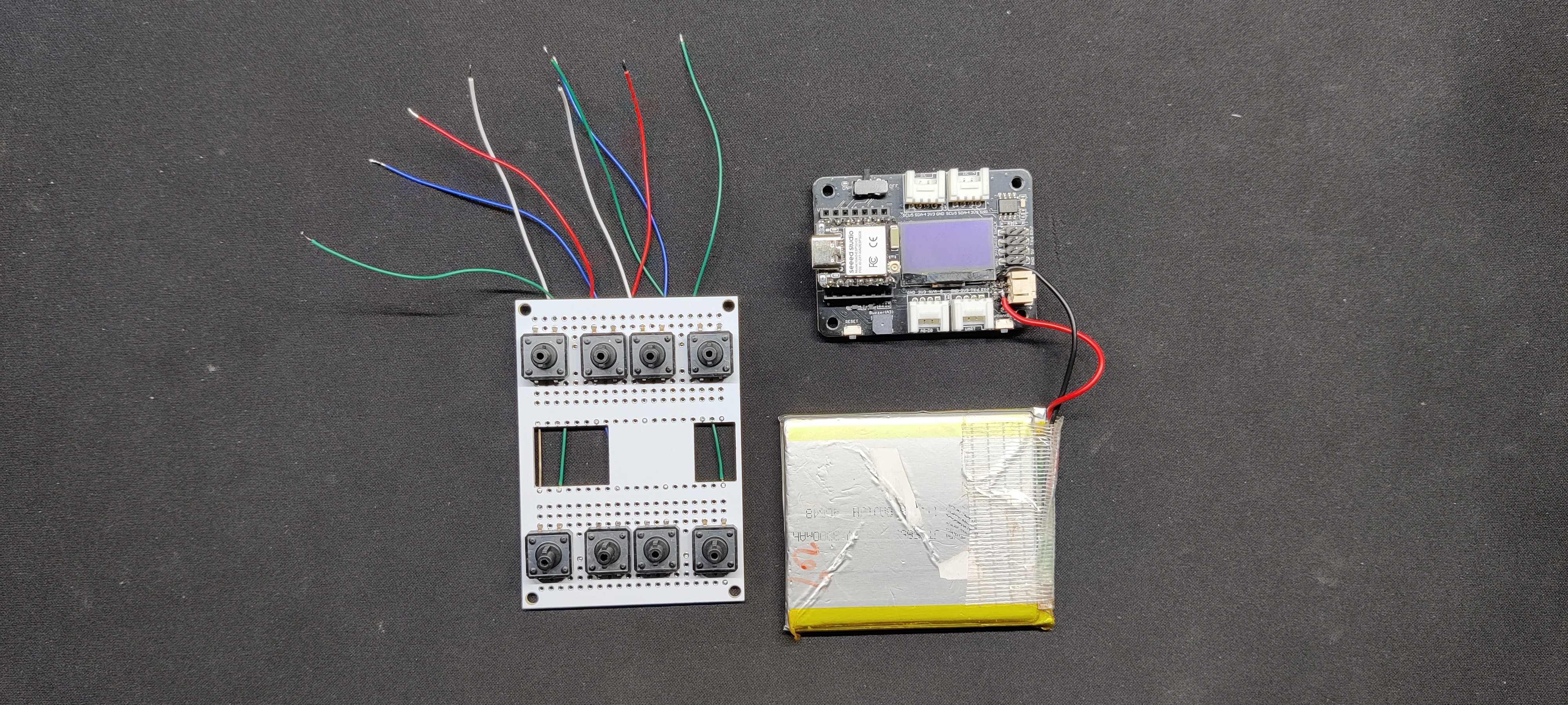
Power Source
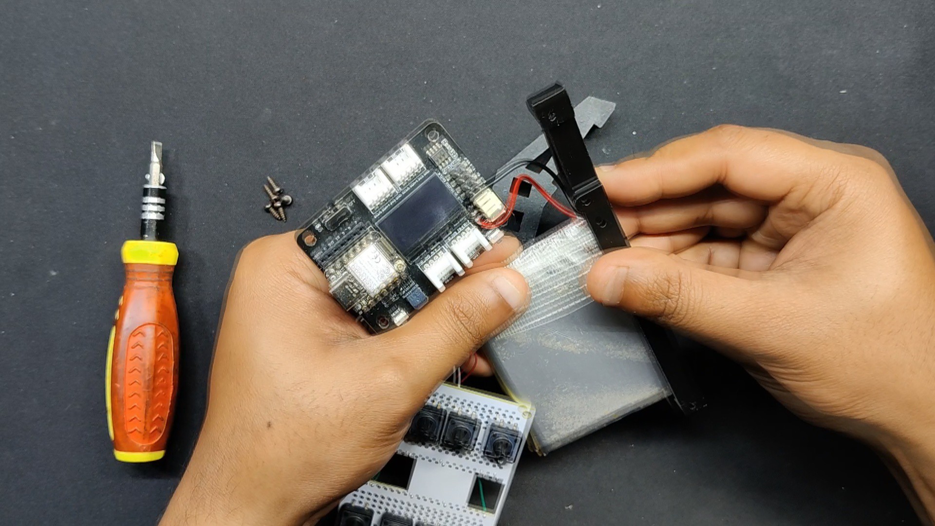
We are utilizing a 3000mAh 3.7V LiPo cell that was recovered from an old cell phone to power the XIAO setup. In order to enable the user to run the XIAO using the attached lithium cell and even charge it through the XIAO microcontroller, we linked the positive and negative terminals with the battery connector found on the XIAO expansion board, which has a lithium cell charging IC.
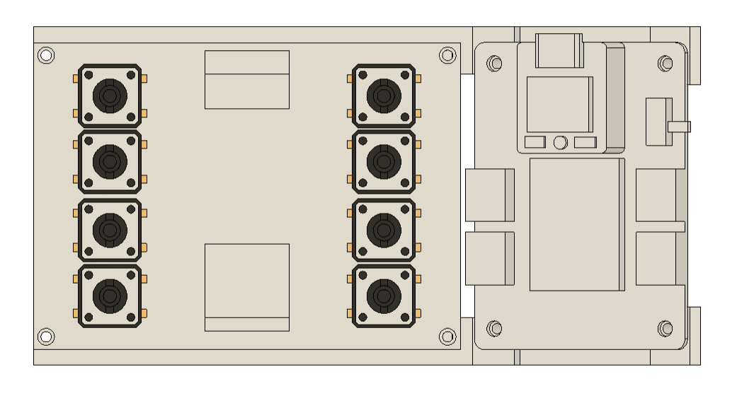
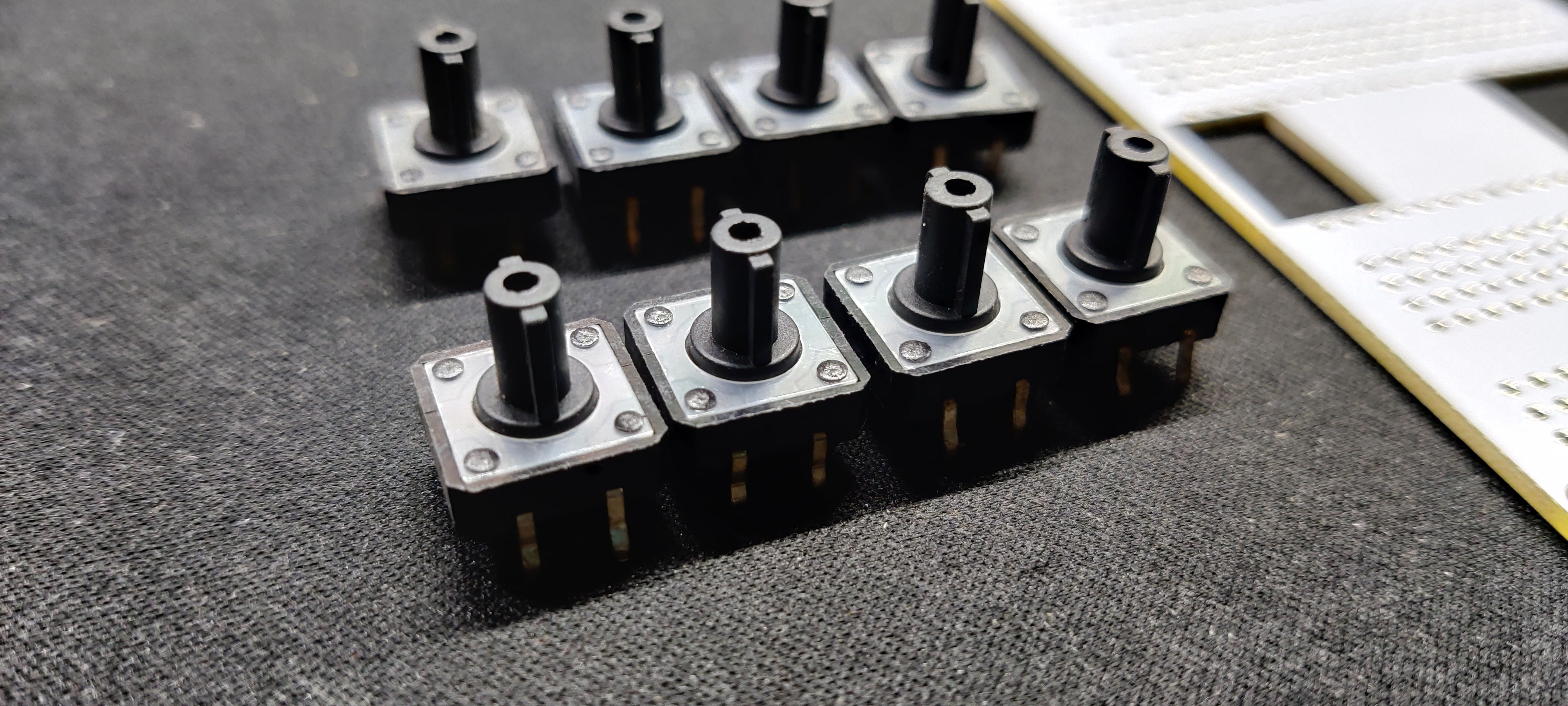
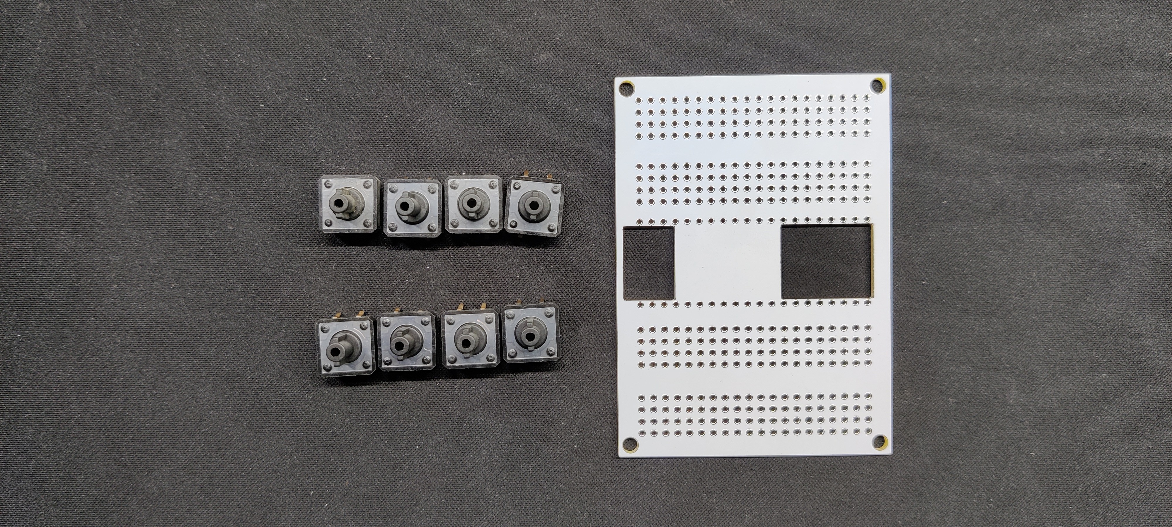
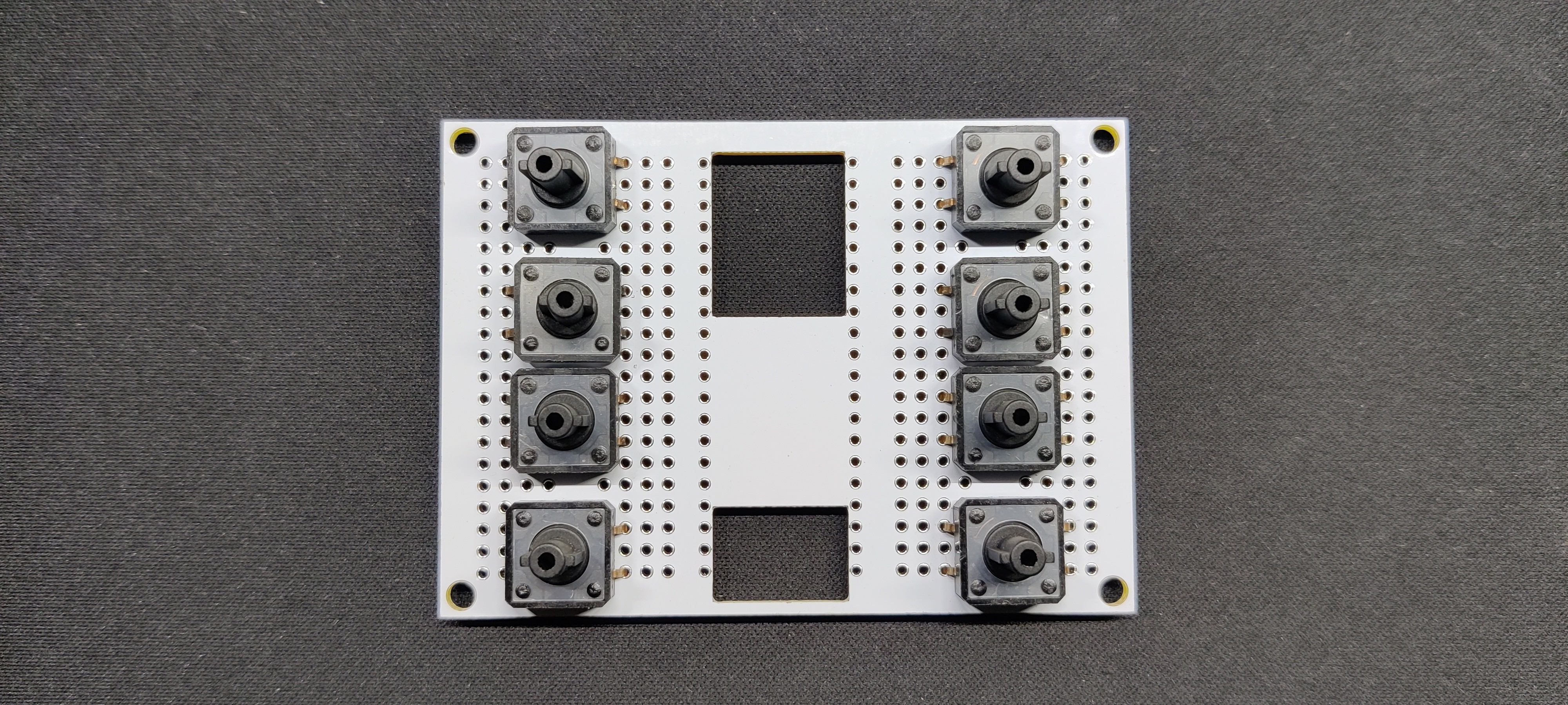
Button Board
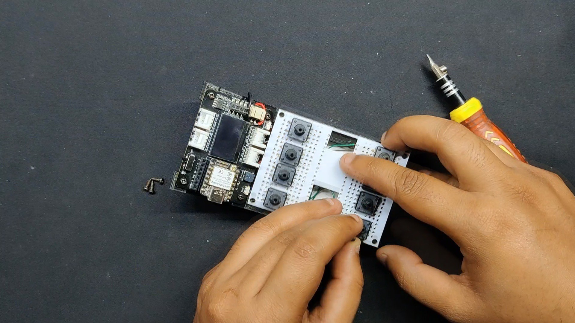
We used one of our previously produced prototyping boards to prepare the button board, and eight push buttons measuring 12 mm by 12 mm were placed on the board.
We solder each button terminal from the back and secure them in position.
These libraries are included to control the I2C communication (Wire.h) and to interface with the SSD1306 OLED display (Adafruit_GFX.h and Adafruit_SSD1306.h).
const int buttonPins[] = {0, 1, 2, 6, 7, 8, 9, 10}; // Button pinsconst int buttonCount = 8;const int speakerPin = D3; // Speaker pinconst int frequencies[8] = {523, 587, 659, 698, 784, 880, 988, 1047}; // C5 to C6
This specifies the GPIO pins used for buttons and the speaker. Also defines the frequencies corresponding to each button, representing musical notes from C5 to C6.
3
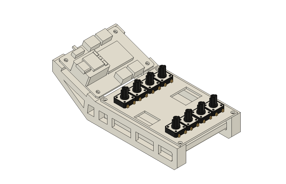
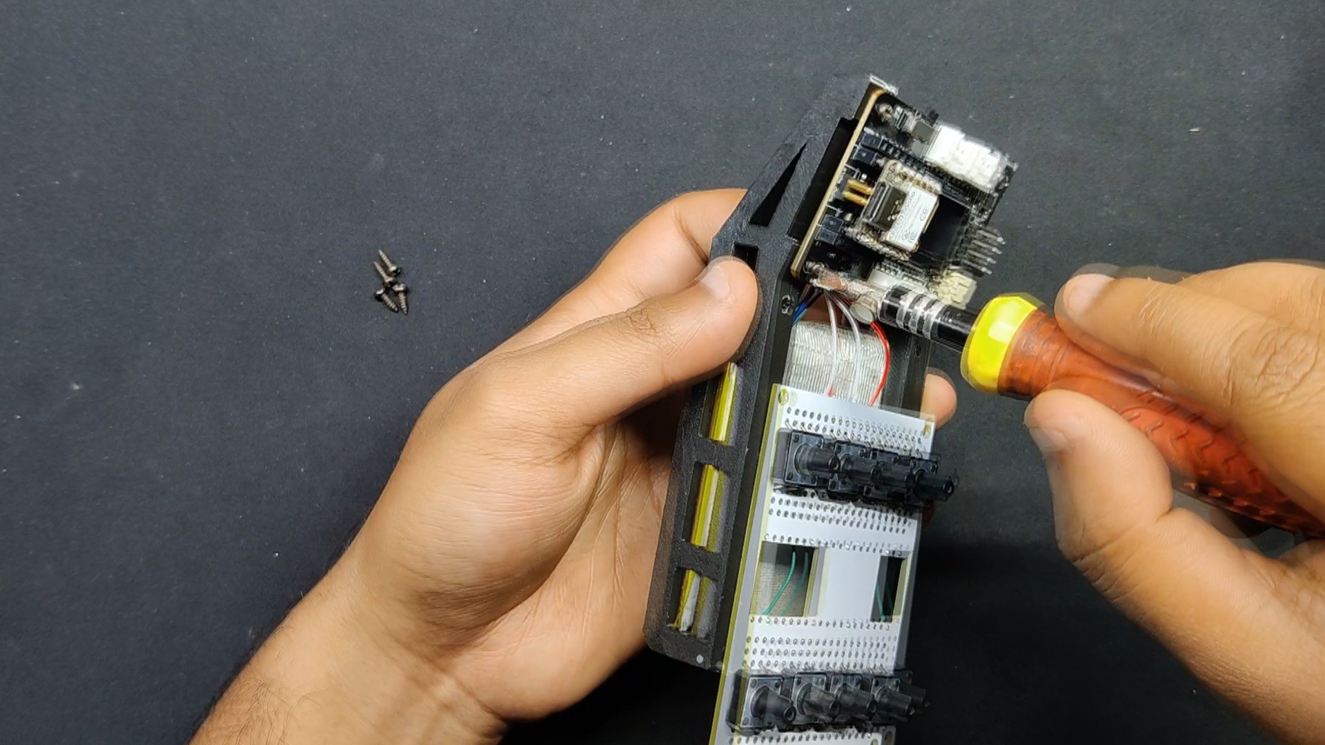
Final Assembly
Following the completion of the electronics and coding, we began the main assembly procedure, which begins with the battery positioned between the two frames. The Xiao expansion board is then installed in its location, and it is fastened in place with M2 screws.
The button board is then positioned and fastened in place with M2 screws.
 Arnov Sharma