Background
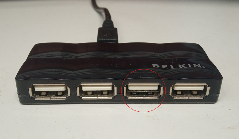
While researching PCB-based USB connectors, it occurred to me that there is quite a lot of empty space inside a USB-A port - around 12x8x2.5mm in fact! This is more than enough to accommodate a small microcontroller and associated components. And so the idea of Hidden HID was born - a USB device that fits entirely inside the port, with the components on the bottom side of the PCB, opposite the contacts.


Electronics
For this concept to work, I needed to minimize the height of both the components and the PCB itself.
I settled on a 2-layer 0.4mm PCB stackup; this is close to the minimum thickness for a rigid PCB. I chose black solder mask to keep it as inconspicuous as possible. The top layer is reserved for the USB contacts, leaving only the bottom layer for components and routing.
For the microcontroller, I chose an STM32F042G6U6. Measuring just 4x4x0.6mm, this was one of the smallest USB-enabled microcontrollers I could find. It also does not require an external crystal to use the USB, which helps minimize component count
An LDO to step the 5V USB supply down to 3.3V for the STM32 and a few decoupling capacitors complete this very minimal circuit.

Mechanical
As the PCB is so thin, some sort of spacer is required to maintain contact with the USB pins and prevent short circuits. To ensure a stable design, I wanted a total thickness of around 2.3-2.4mm. Subtracting 0.4mm for the PCB means I needed a spacer with a height of around 1.9-2mm.
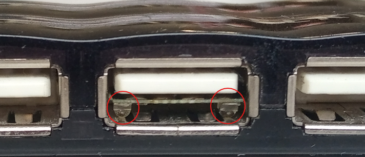
I decided the easiest solution would be to find a couple of small passive components with the desired height and solder them to both edges of the board. Unfortunately, most SMD components this tall are also too long or wide to fit on such a small PCB. The only option was LEDs; these tend to be taller than other components with the same footprint, due to the additional height needed for the lens. I selected some LEDs with a 1206 footprint and a height of 1.8mm, which just about fit on the PCB when relaxing the design rules a little ;) These LEDs have a purely mechanical function and are not currently part of the circuit. In a future revision, I may replace them with IR phototransistors for some basic remote control.


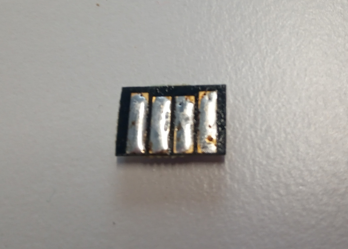
In the end, the LEDs turned out to be not quite tall enough and the connection was unreliable. Only after adding a thin layer of solder to the USB contacts could a stable USB connection be achieved.

I found that one LED on each side was not enough - this caused the board to tilt. A minimum of 3 LEDs were required to keep it level; 2 on the left and 1 on the right.
You may be wondering how to remove the device from the USB port. This is surprisingly straightforward; I simply take some tweezers, insert them behind the singular LED on the left, and pull. To avoid short circuits, I make sure the computer is off (or the hub unpowered) before removing. A small 3D printed extraction tool could probably allow removal while powered, but I am lazy
Firmware
At the moment, the firmware is very simple. The device wakes up every couple of minutes, enables the USB, makes the cursor jump about, and repeats.
TODOs
- Write a bootloader so that the firmware can be updated over USB
- Adapt the firmware to emulate a keyboard, enabling keystroke injection and malicious code execution
- Replace one of the spacer LEDs with a phototransistor and adapt the circuit accordingly, to implement some basic remote control