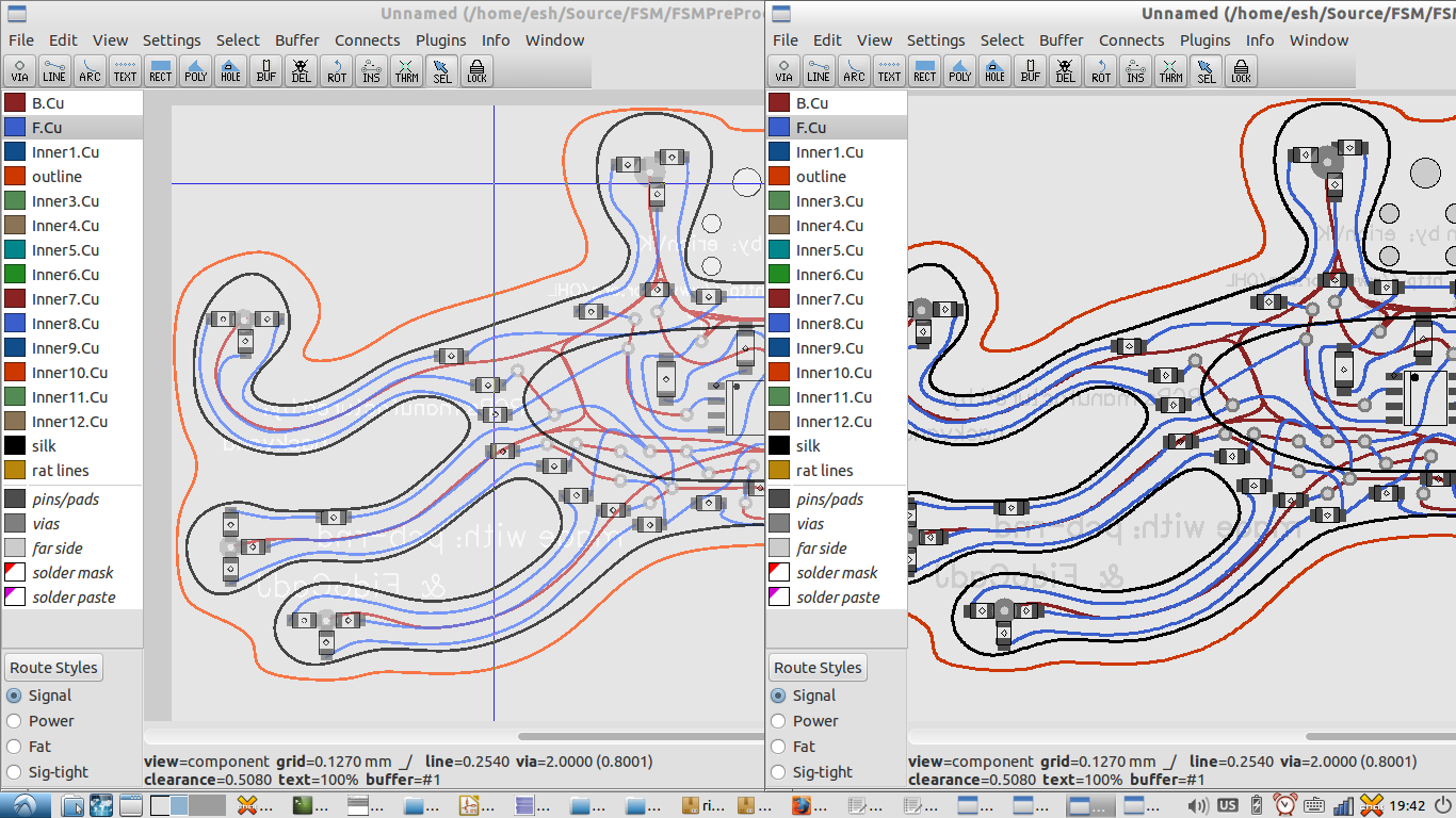
Free form trackwork employing beziers or cubic splines in the usual FOSS/crippleware EDA offerings is not trivial.
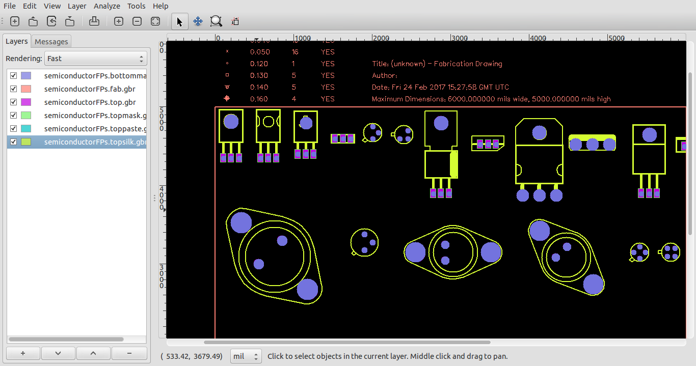
Part of the difficulty stems from the Gerber format (which a PCB destined for manufacture will typically end up being represented by) supporting arcs, polygons and lines, and flashed apertures, but not beziers or cubic splines.
Some of the more dedicated practitioners of the art use graphic design tools such as InkScape to generate the paths required for the layout, and then convert them with various scripts to layouts.
Obvious difficulties with this include scaling, and representing the basic layout in Inkscape as a template against which tracks can be laid. Additionally, desktop publishing and graphic design tools don't usually come with useful libraries of component footprints.
My usual PCB layout editor is pcb-rnd, a fork of the gEDA PCB layout tool.
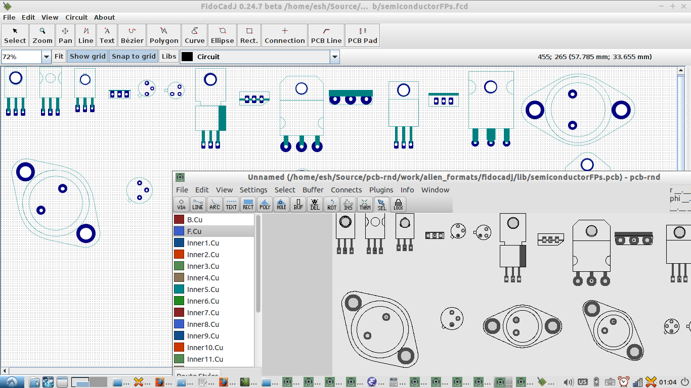
The pcb-rnd project has been on a bit of an import/export module frenzy lately, and when FidoCadJ was stumbled upon, the natural thing to do was to implement an export module to FidoCadJ layout format.
FidoCadJ is an easy to use cross platform Java application that allows schematic creation and also PCB board layout. It has a 5mil grid, and a good library of basic footprints. It is a successor to FidoCad, a C++ program first used in the 90s in Italy to share schematic and layouts on Usenet in a compact format.
FidoCadj exports in a variety of formats, including SVG, pdf, and ps, but lacks Gerber output. It does, however, natively support cubic beziers and cubic splines.
Excited by the possibility of a very natural and simple method of achieving freeform, artistic track and outline design on PCB layouts, the logical thing was to add an export module to FidoCadJ to export pcb-rnd/PCB (.pcb) layouts which would include the beziers and cubic splines converted to line elements.
The FidoCadJ repo was cloned locally, and emacs was fired up.
The FidoCadj code is very nicely structured, and I was able to use an unpopulated skeleton for an Eagle export module that was there as a basis for the gEDA exporter.
FidoCadJ is interesting as it expresses footprints and symbols as a one line "macro", which is defined in libraries. Default standard library macros are not routinely "exploded" on saving, but non-standard, local macros can be.
The FidoCadj exporter code allows macros to be dealt with by the exporter module, or "exploded" into primitives by the Export "overseer" code which can then be submitted individually for processing by the currently invoked exporter.
In the case of gEDA pcb-rnd/PCB, footprints primitives are not a subset of the layout elements, and have slightly different formatting. For this reason, the exporter code has to explicitly deal with the full macro definition and do its own parsing, returning footprint appropriate primitives wrapped in a single footprint Element[]() wrapper in the layout file.
Once this was appreciated, implementation of the exporter proceeded smoothly.
A motivated Java coder could implement a similar exporter for KiCad if keen, but pcb-rnd exports to Kicad anyway, and can be run headless as a command line batch conversion utility, so it would now be a bit of a duplication of effort for a KiCad user to code an exporter in FidoCadJ.
The FidoCadj exporter code has been cleaned up to suit the FidoCadJ style guide, and has now been incorporated into the FidoCadJ git project mainline.
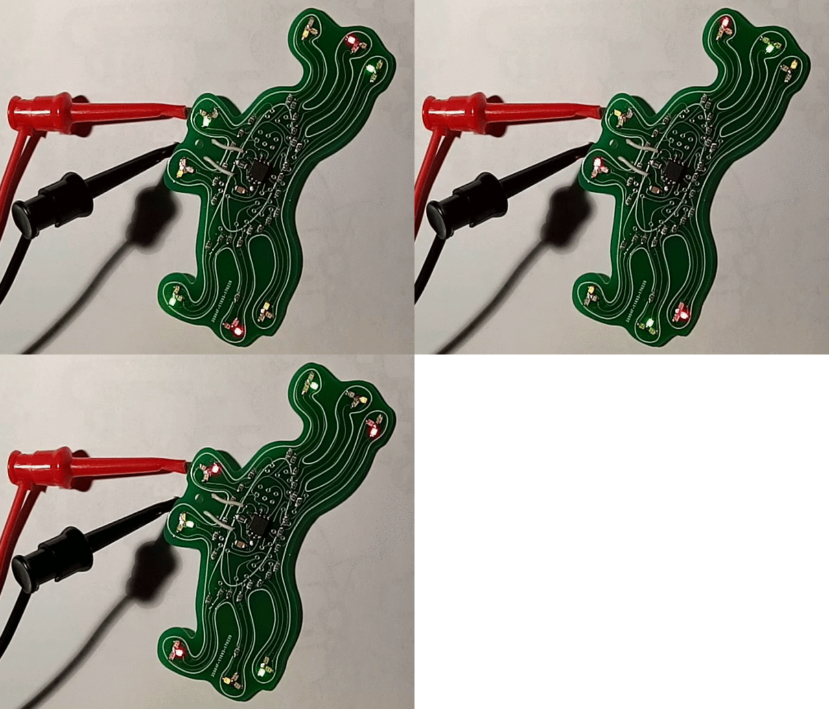
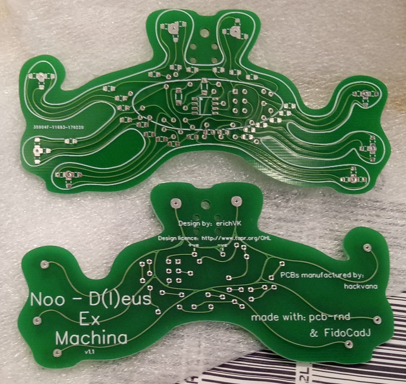
Import and export code like this requires testing, and to test the newly implemented, a suitable layout was conceived....



 Elecrow

 mbsg99