Ramón Calvo
-
How to program the calculator using a KL25Z board
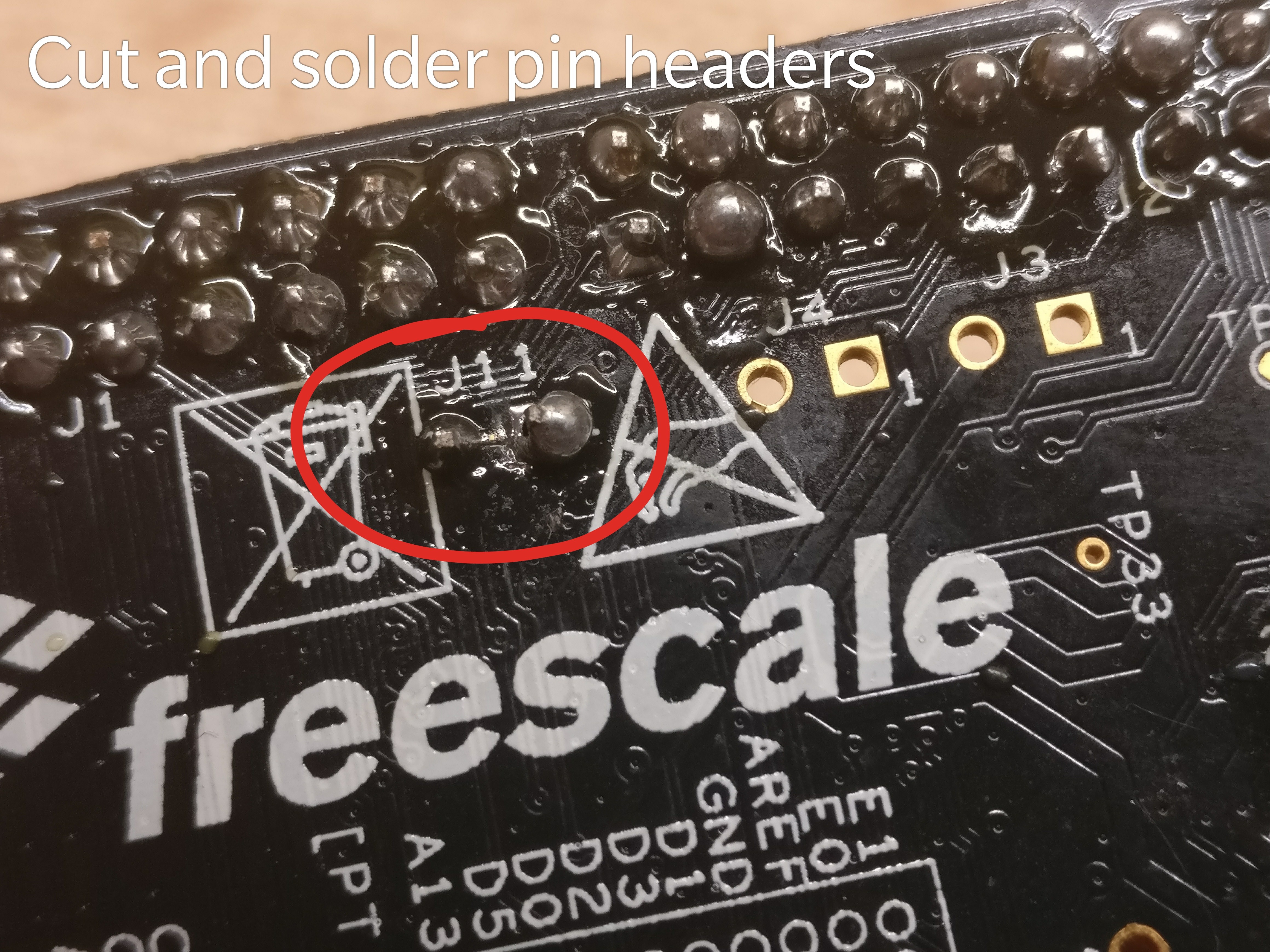
10/15/2017 at 17:45 • 1 commentOnce the calculator is mounted, we no longer can program the MCU from a USB interface. To solve that inconvenience, we need to prepare the KL25Z so it can act as an SWD programmer. The theory is simple, disconnect the internal SWD to the KL25Z's MCU and connect it directly to the calculator's.
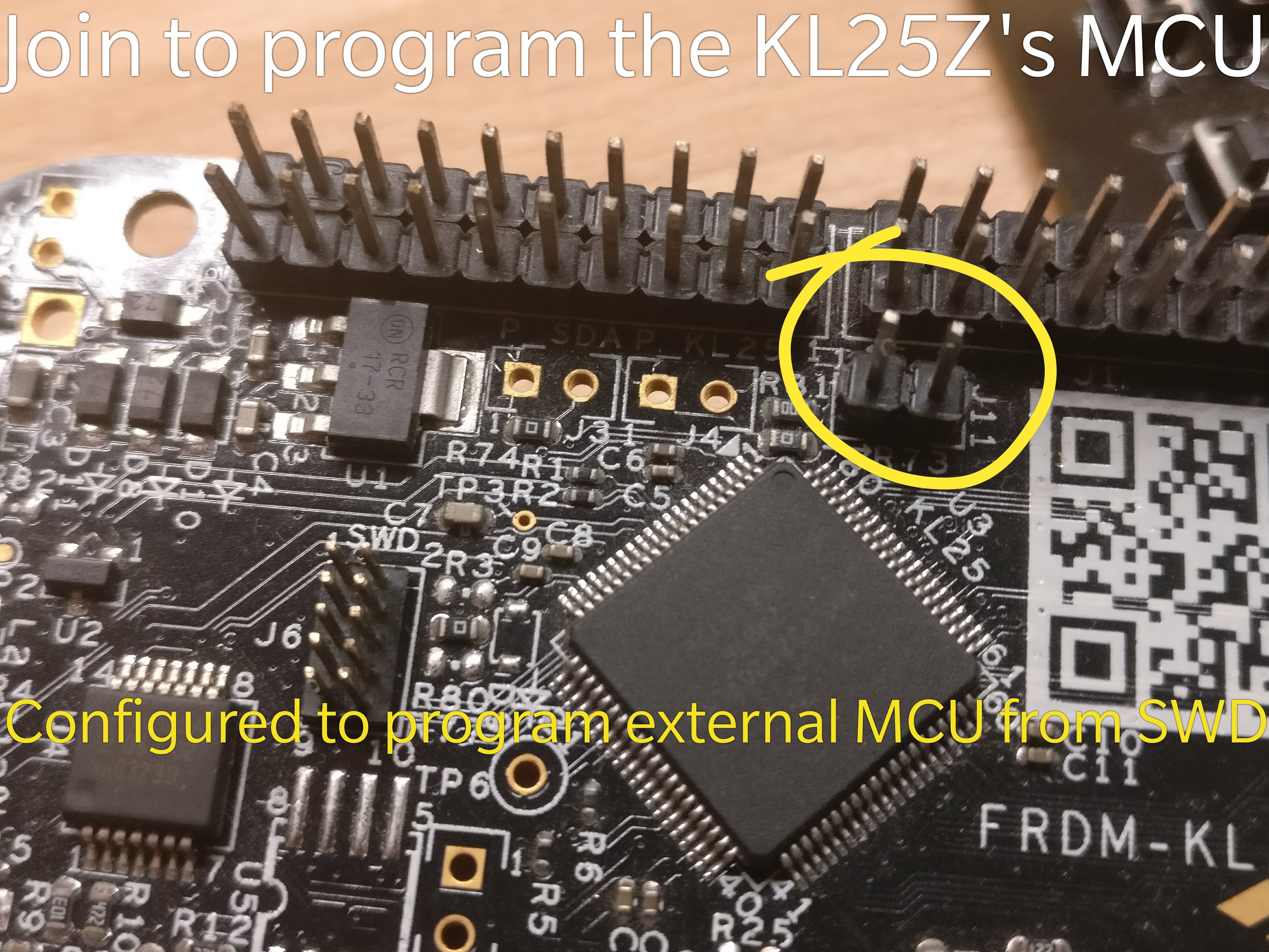
To isolate the MCU from the SWD interface, we need to cut J11, according to the manual.

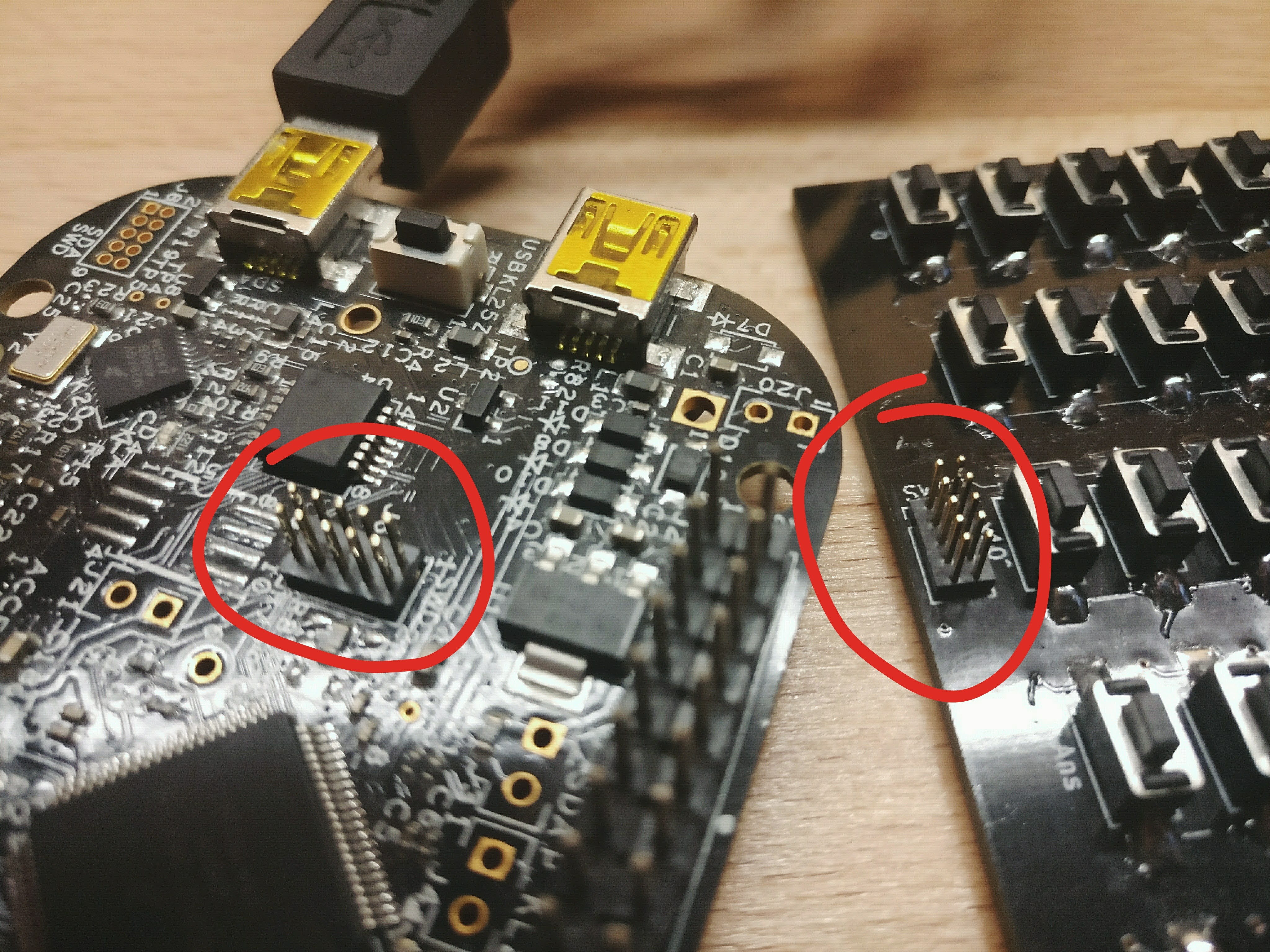
Credit to mcuoneclipse.com And now we need to solder the male 1.27mm 2x5 pin headers so we can use a cable to connect the programmer and the calculator.
To program the calculator, since we are still using mbed's firmware, we can just drag and drop the files over USB, or as I do, use PlatformIO to automatically upload it.
-
Migrating project to PlatformIO
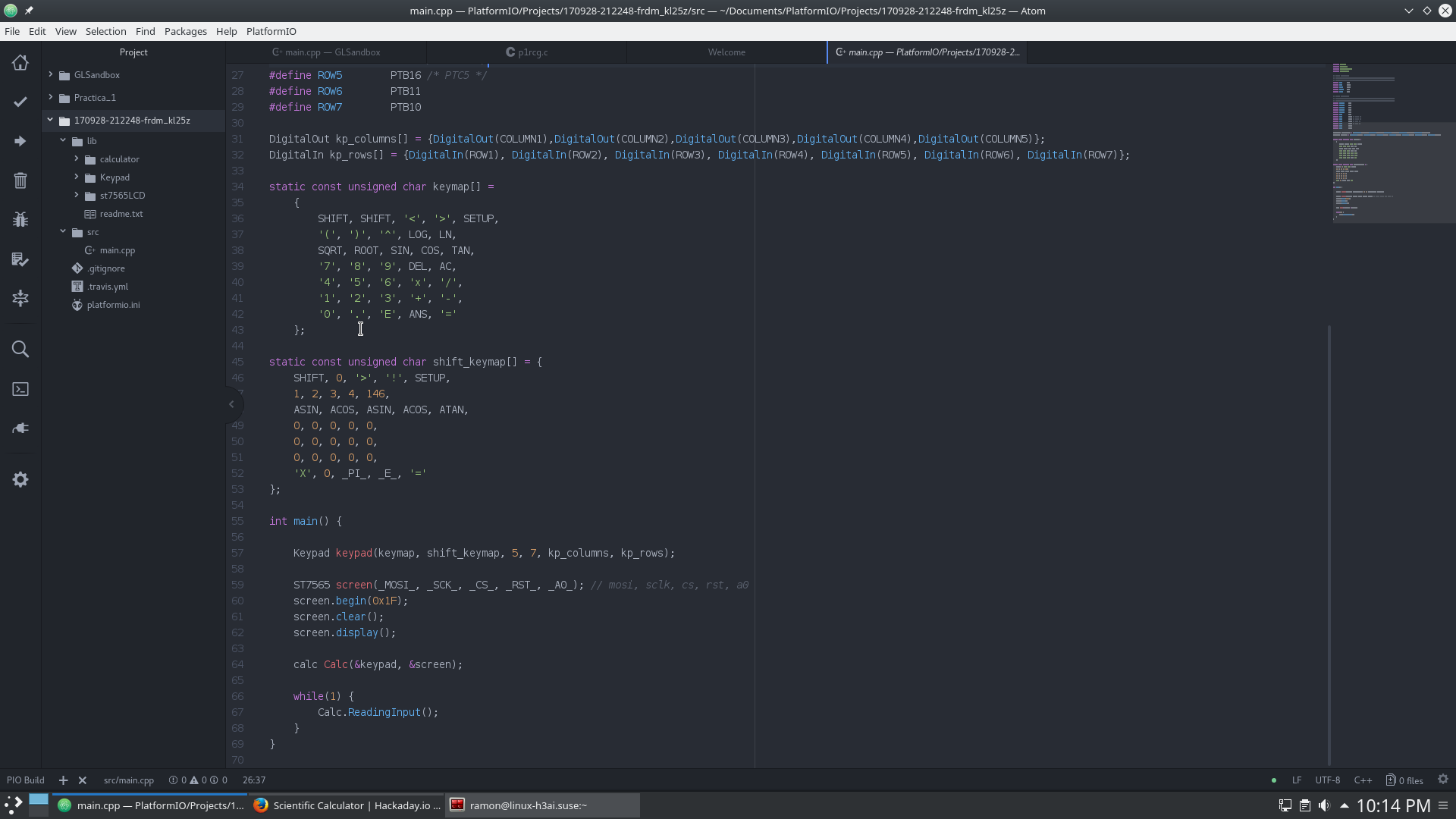
10/12/2017 at 20:31 • 0 commentsI haven't been updating this project for a while. One of the reasons was the messy mbed online IDE. The larger the code, the slower the response of the browser. But lately I've been tinkering with Atom and discovered the plugin PlatformIO. PlatformIO has lots of development boards already configured and it worked almost out-of-the-box. The good thing about this is that now I can edit the code and compile anywhere with no need of the Internet. Also, from now on I will publish the source code on GitHub.
The migration was done 'by hand'. I couldn't find any export option in the mbed IDE that matched the configuration PlatformIO used. However this was not difficult and was done in under 5 min.
Also, if you want PlatoformIO to flash the KL25Z directly, change the upload_port in platformio.ini to this (make sure the board is mounted):
upload_port = /run/media/"user"/FRDM-KL25Z/ -
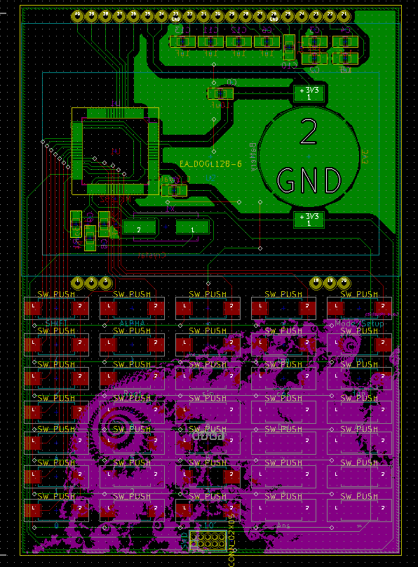
Releasing schematic and source code
02/22/2017 at 15:45 • 0 commentsAbout the circuit:
- A day after I ordered the PCBs I realized I had forgotten to put a power switch on the board. I thought maybe using sleep modes and wake-ups by interrupts I could solve that problem but to my disappointment the MKL25Z only has interrupts in ports A and D, and I connected the keypad to B and C. Because of this the calculator powers on and off putting in and taking the battery out (sighs).
- I also forgot to design a reverse voltage protection circuit, which combined with the previous problem becomes a great danger.
- If you want to replicate the PCB please make sure that the silkscreen doesn't overlap the SWD programming interface (very important)
About the code:
The library used to drive the LCD was made by [imachooon]. Thank you for your library [imachooon].
The code is not finished at the time of writing (and probably won't be for a long time) and can present some bugs, but it works.
-
A summary of almost a year
02/17/2017 at 22:49 • 2 commentsI started this project in February of 2016, but it hasn't been a continuous work, here is a summary:
The first problem I encountered making the calculator was obviously the parsing. Being unable to come up with a solution, a quick Google search led me to something called Reverse Polish Notation and a sweet algorithm invented by Edsger Dijkstra called shunting-yard algorithm. Explaining all of this in detail is beyond the scope of this text, but to understand it, RPN gets rid of every parenthesis and makes it easy to make the calculation (with the shunting-yard algorithm). More about that here: Shunting-yard algorithm and RPN.
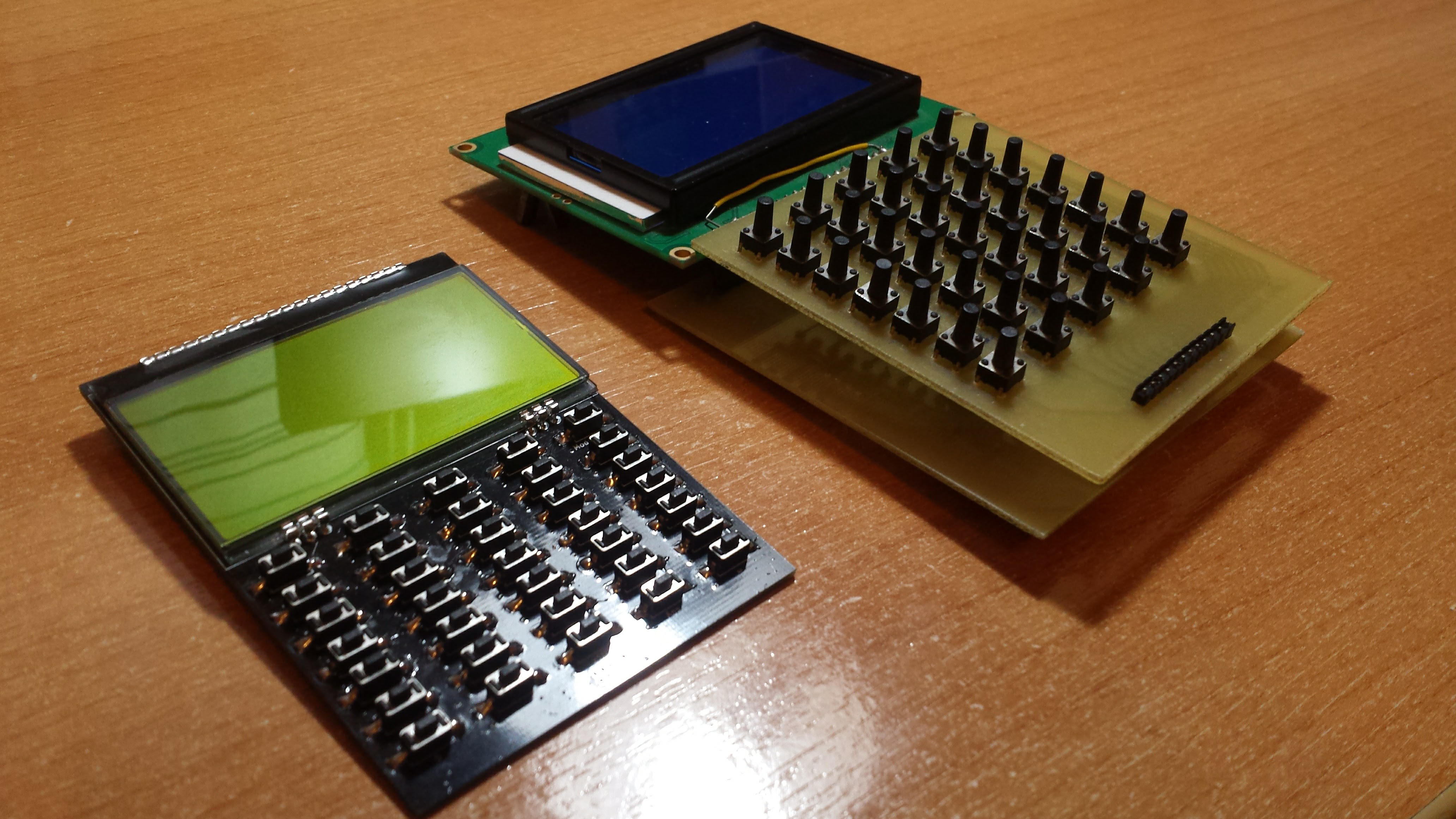
The above, combined with the keypad, were the 'funny' thing to program. The rest was a bit tedious. I also have to say that originally this was an Arduino project, but I didn't quite liked the result, it needed a 9V battery, wasn't low power at all and was bigger than my hand. And also didn't have much precision (32-bit float).
That's why I decided to move to mbed, specifically to the Freescale's Freedom KL25Z development board. So I ported the code I had and made a working prototype. Everything went fine but when I tried to get the voltage doubler of the st7920 LCD driver to work I couldn't (that meant I couldn't get the needed voltage for contrast out of a 3V coin cell). That was in July of last year and I gave up. The project had remained in a shoe box for six months until I decided to bring it to an end.
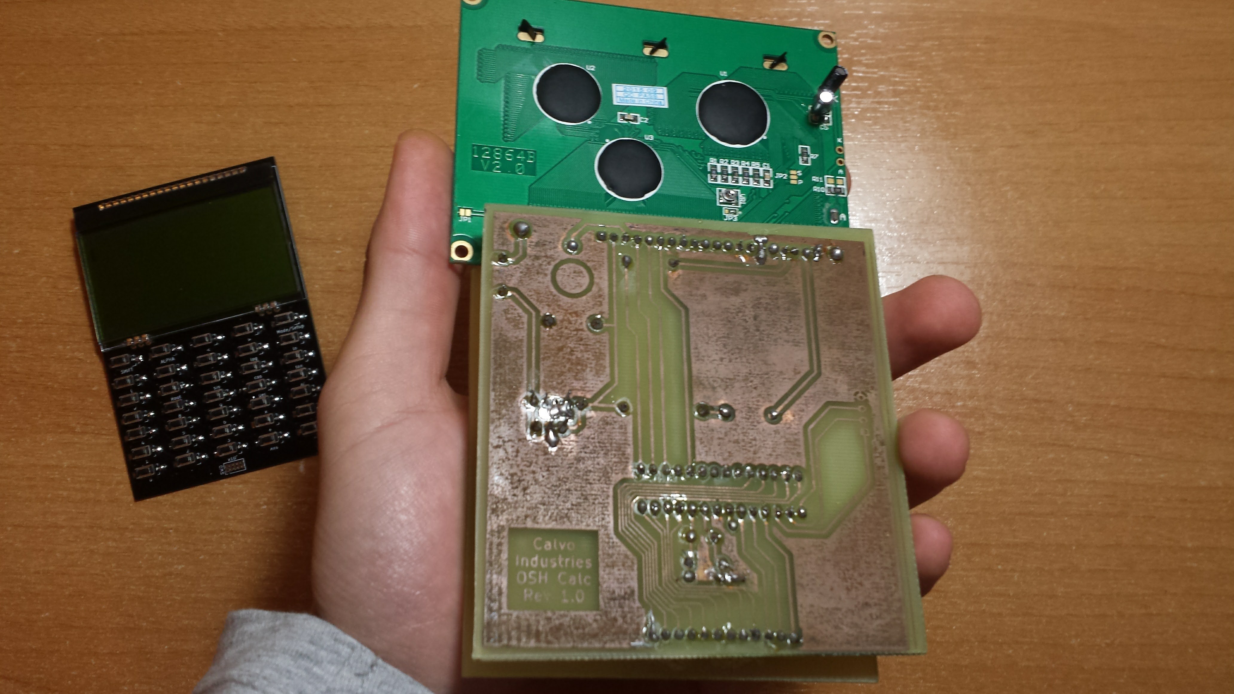
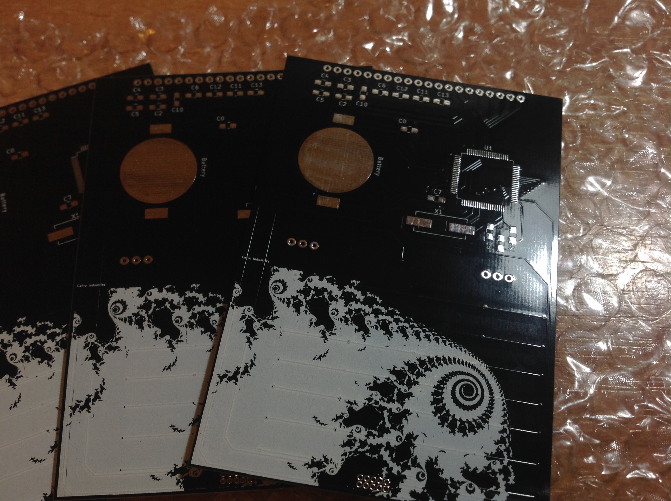
I bought a new LCD and designed the PCB using KiCAD. I got the PCBs manufactured by Elecrow. It was the first time I ordered any PCB but I can say they are very good quality. The bad part was the delivery time (about 25 days).
Although I don't own a soldering station I managed to solder the microcontroller with a cheap soldering iron and a thin tip pin by pin (with the help of a magnifier, of course). SMD was something I had a lot of respect before that day. I finally understand those who say it is even easier than through hole (I mean it's not easier but also you don't need that much experience).
I may have skipped some important steps but that's it. This is a big summary of my year-long (and not yet finished) journey.