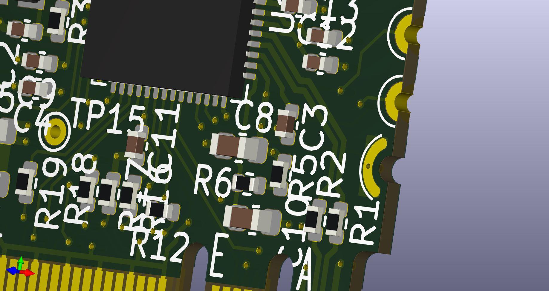
Since a long time I had the idea to simulate castellated pins on a board edge to get around the pricey options to do it as intended by your PCB house of least suspicion. My idea was to have the PCB outline indented by half circles and add a curved pad on top and bottom connected through one or more vias. Wires or pin headers could be soldered to either pad. To solder the board on a prepared carrier footprint ( ESP32 module style) would probably need some extra wires, but that was not the intend of this board anyways.
Here is an image how the 2 pad styles look in KiCAD (please ignore the silkscreen, this layout was far from finished). I probably could have moved the half pad closer to the board edge.

After receiving the boards, I tried to solder pin headers to the pads and ran into several problems. The board was only 0.8mm thick, so there was not much support. With the plastic body on one side, I did solder only the opposite pad to the pin which did not give enough strength. I tried to use hot glue to fix the connector to the board but still managed to rip off pads very easily. Some more pictures of the whole mess.


Overall it was more pain than useful. I would give this idea a -1 out of 11, would not recommend.
 MagicWolfi
Discussions
Become a Hackaday.io Member
Create an account to leave a comment. Already have an account? Log In.