0%
0%
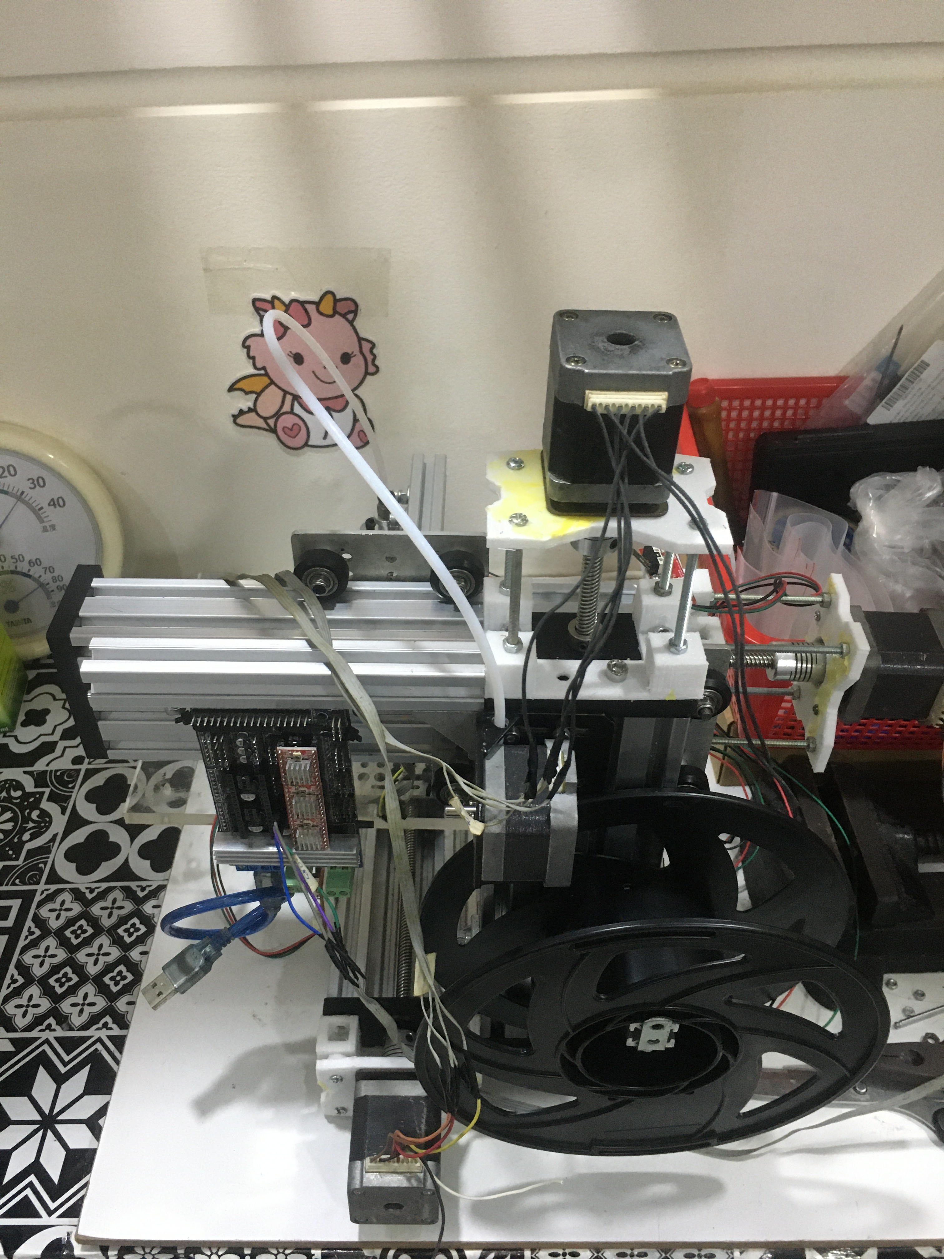
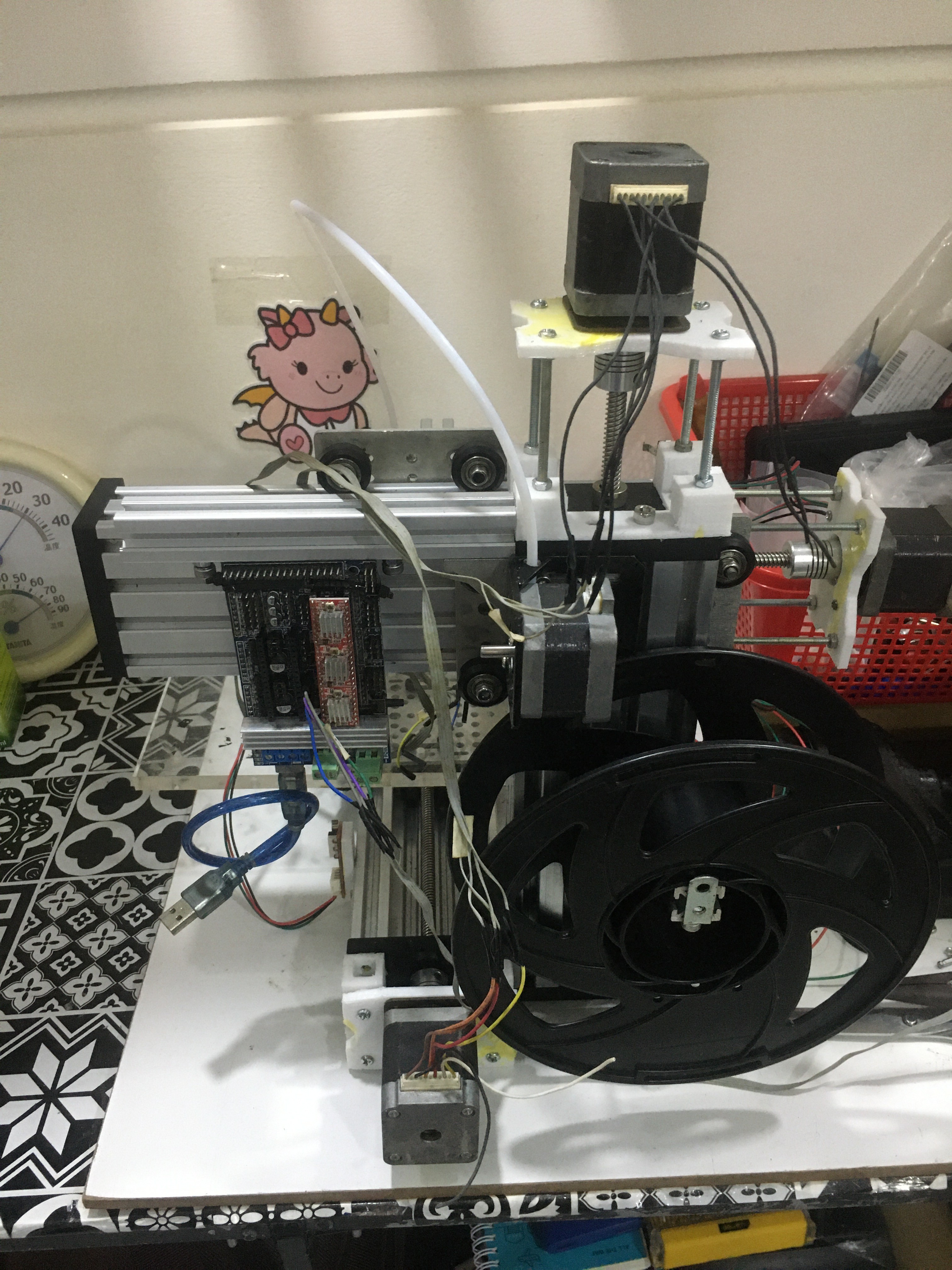
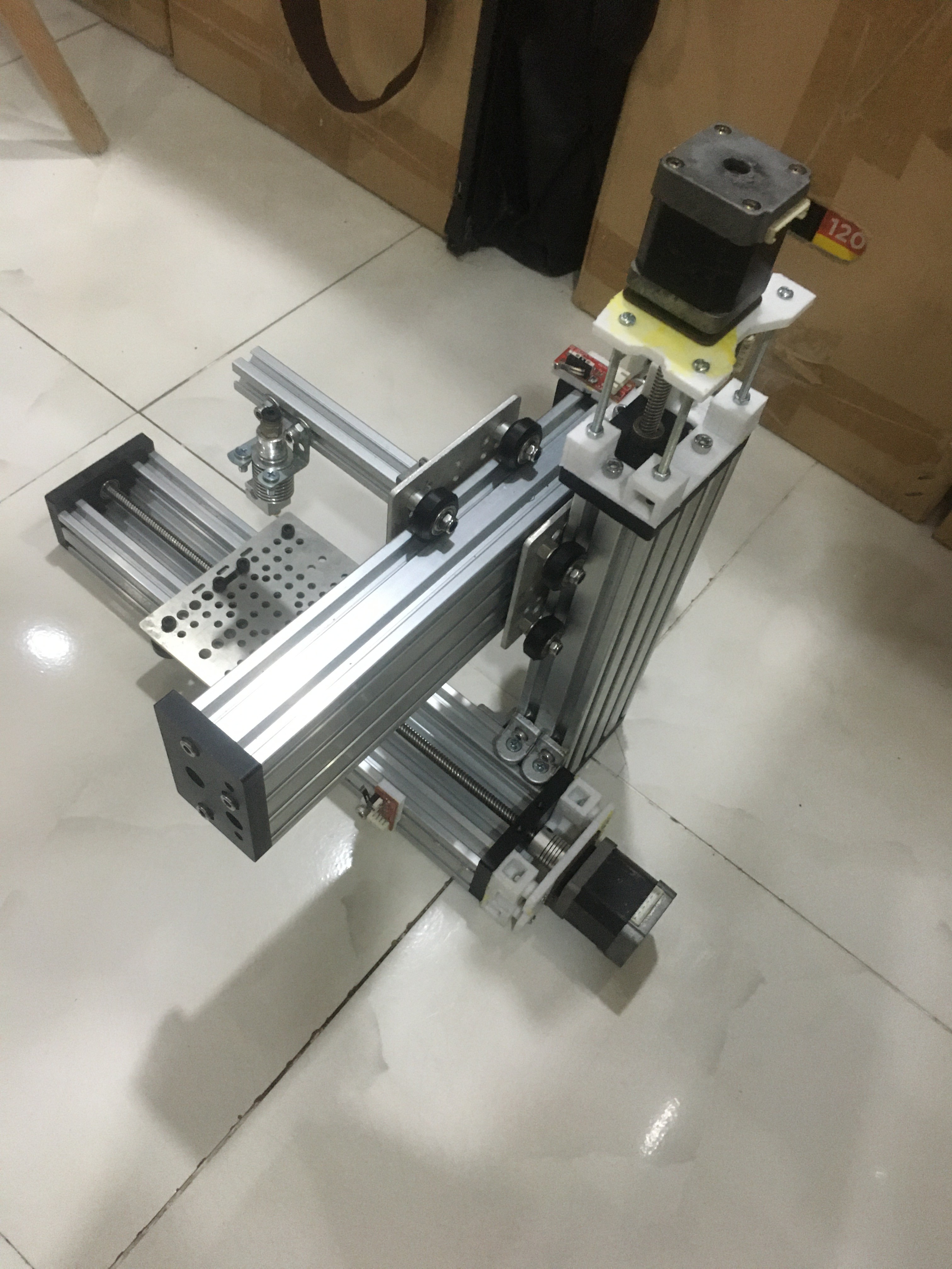
Making a mini 3d printer using C-Beam aluminum
Making a mini 3d printer using C-Beam aluminum frame
 TRAN.VINH.QUANG
Become a Hackaday.io member
Already have an account? Log in.
Just one more thing
To make the experience fit your profile, pick a username and tell us what interests you.
Pick an awesome username
hackaday.io/
Your profile's URL: hackaday.io/username. Max 25 alphanumeric characters.
Pick a few interests
Projects that share your interests
People that share your interests
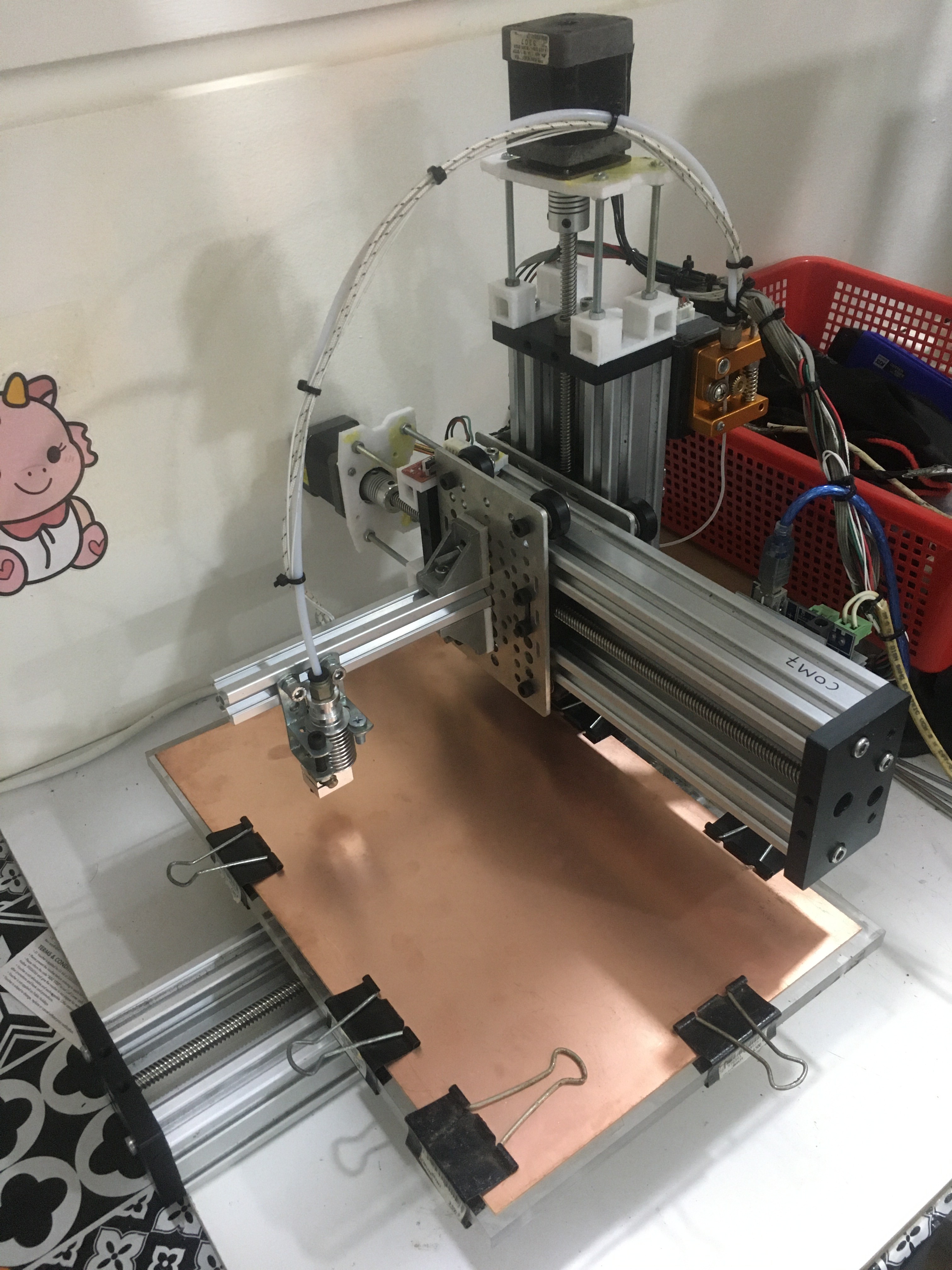
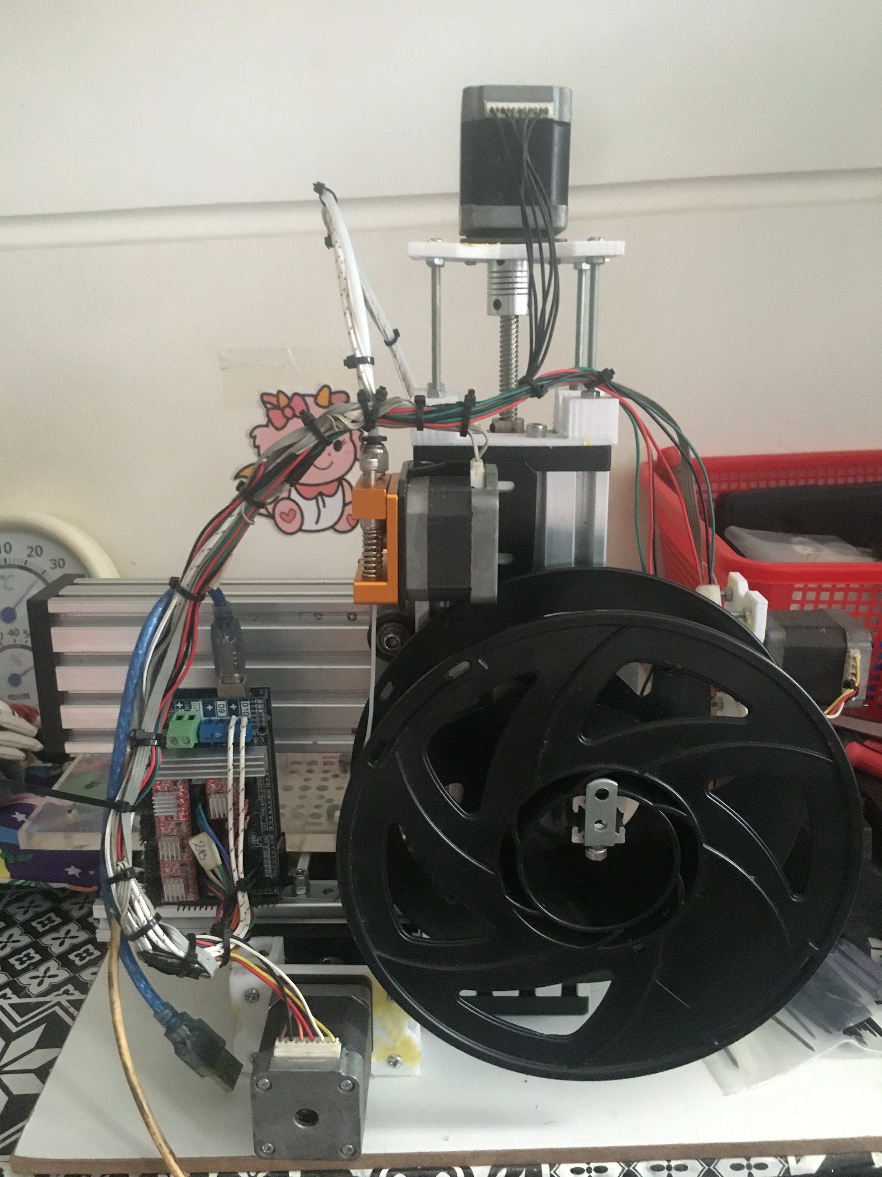
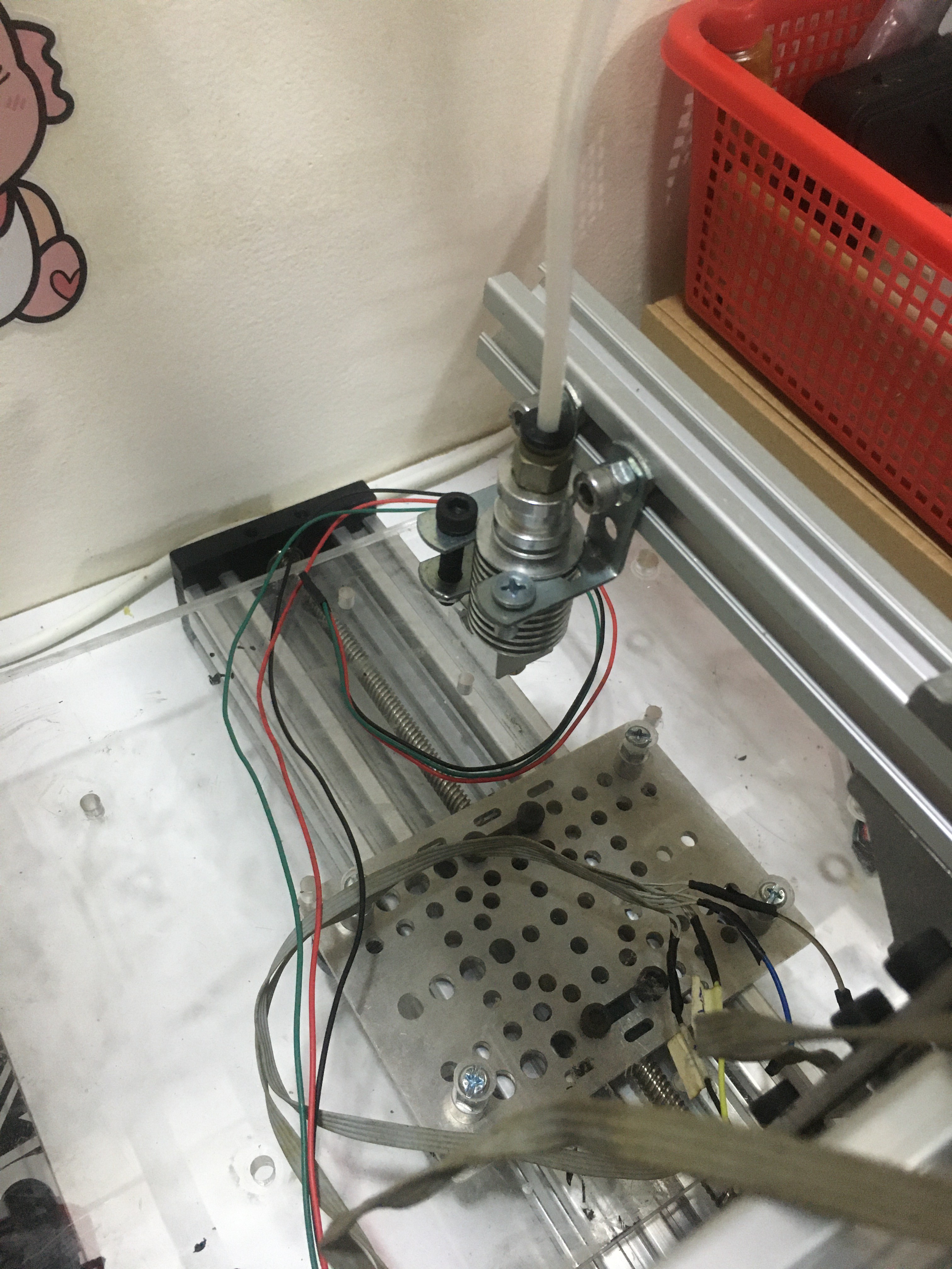
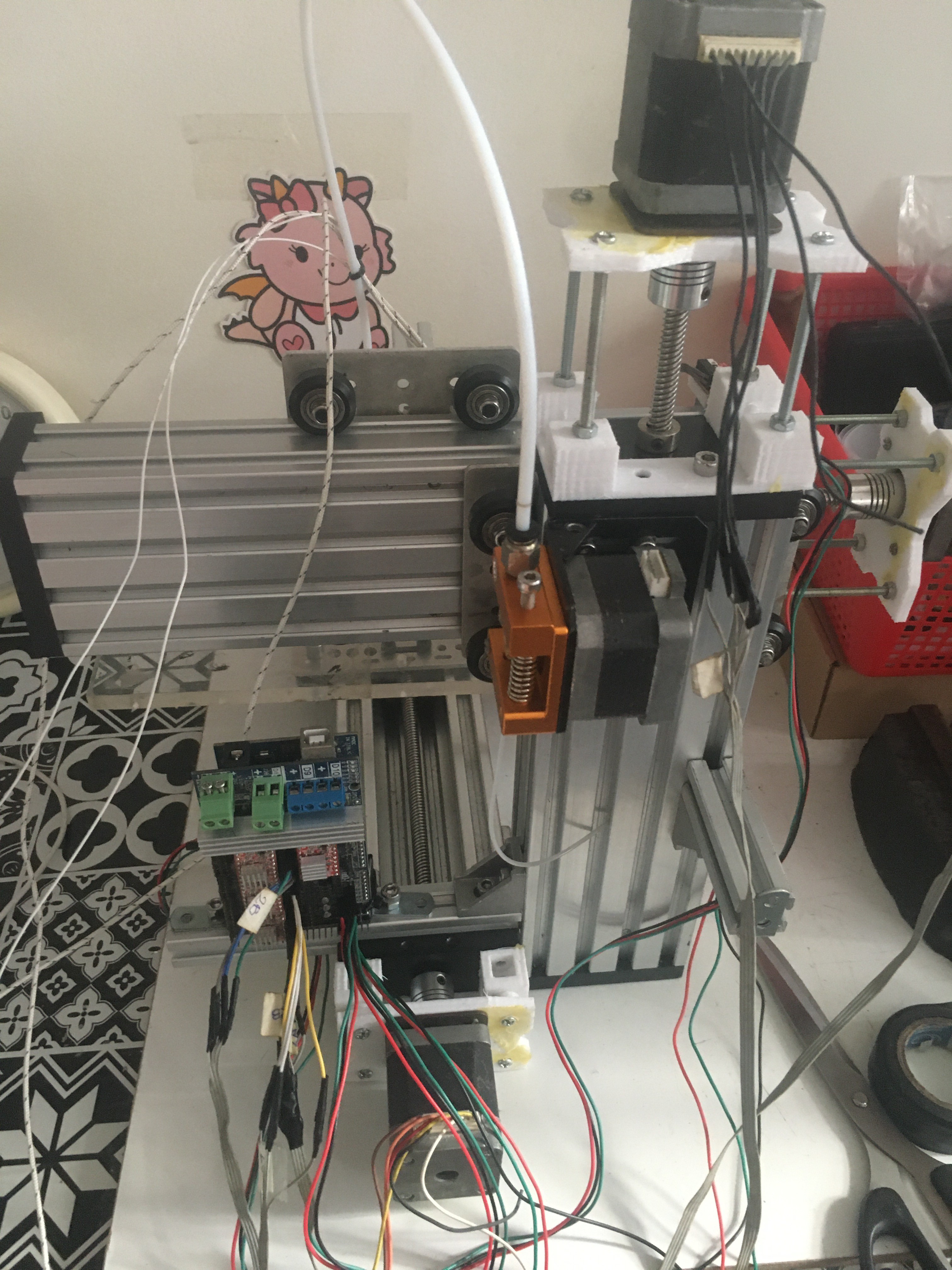
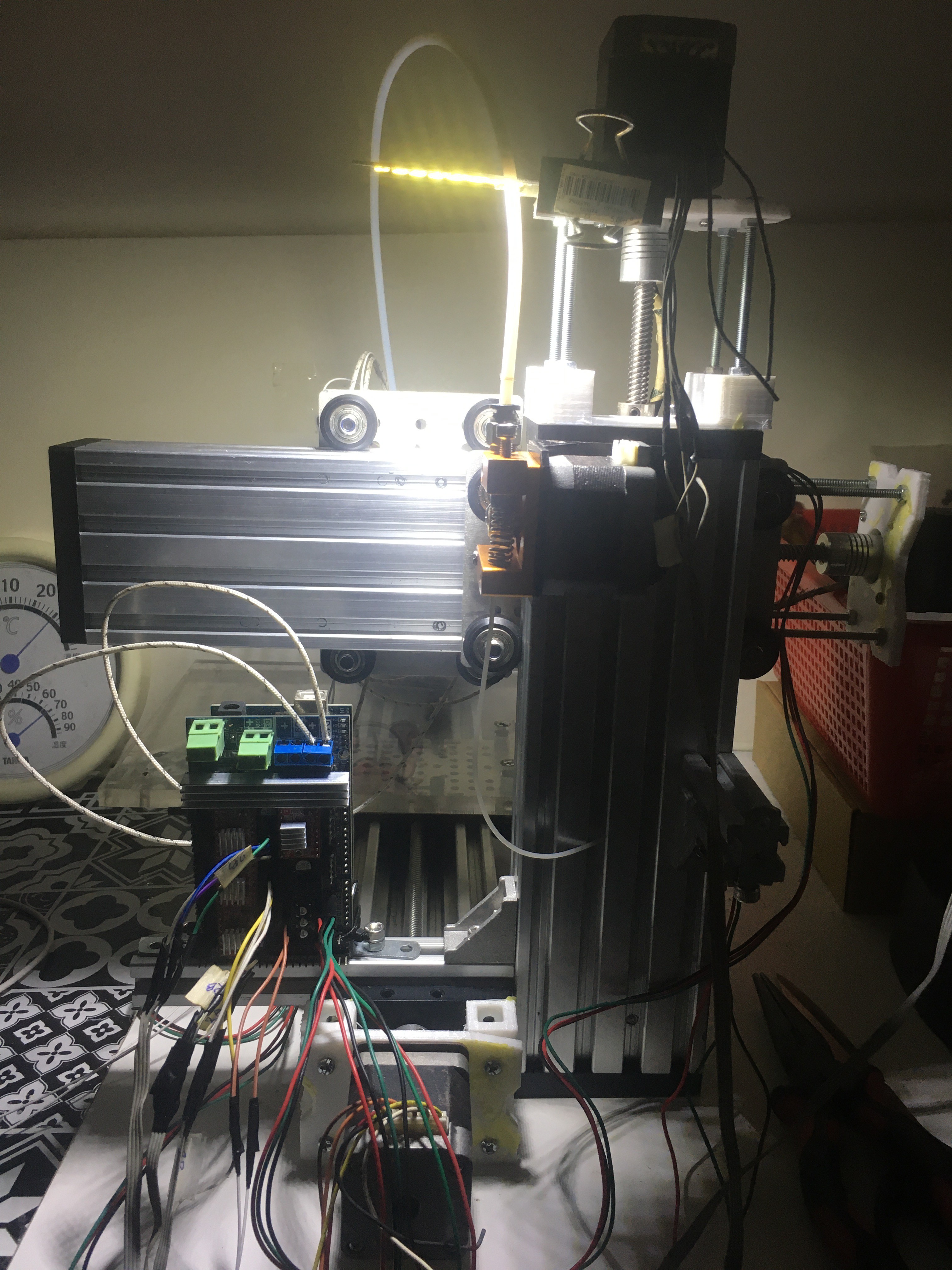
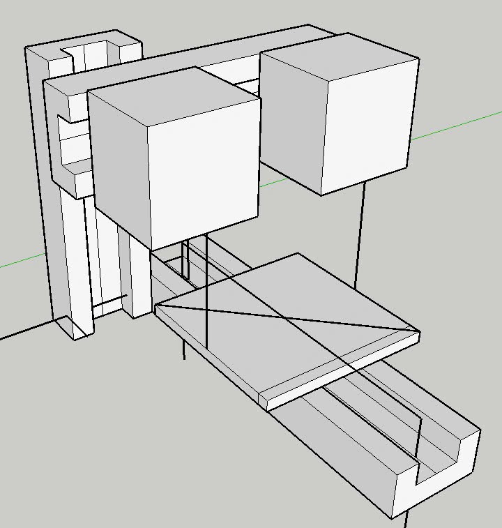
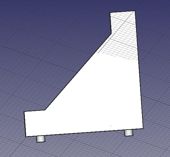
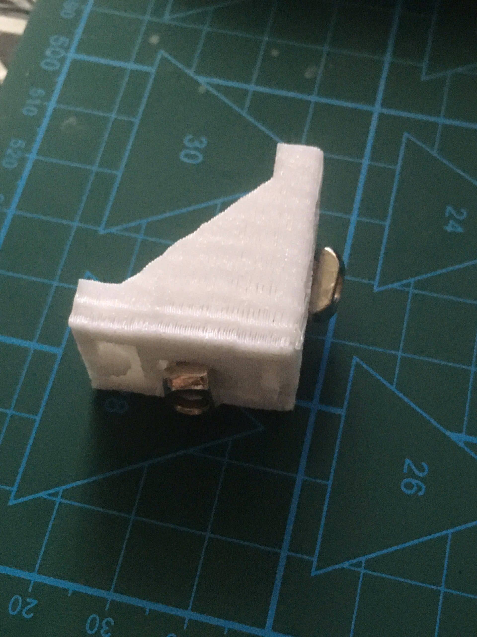
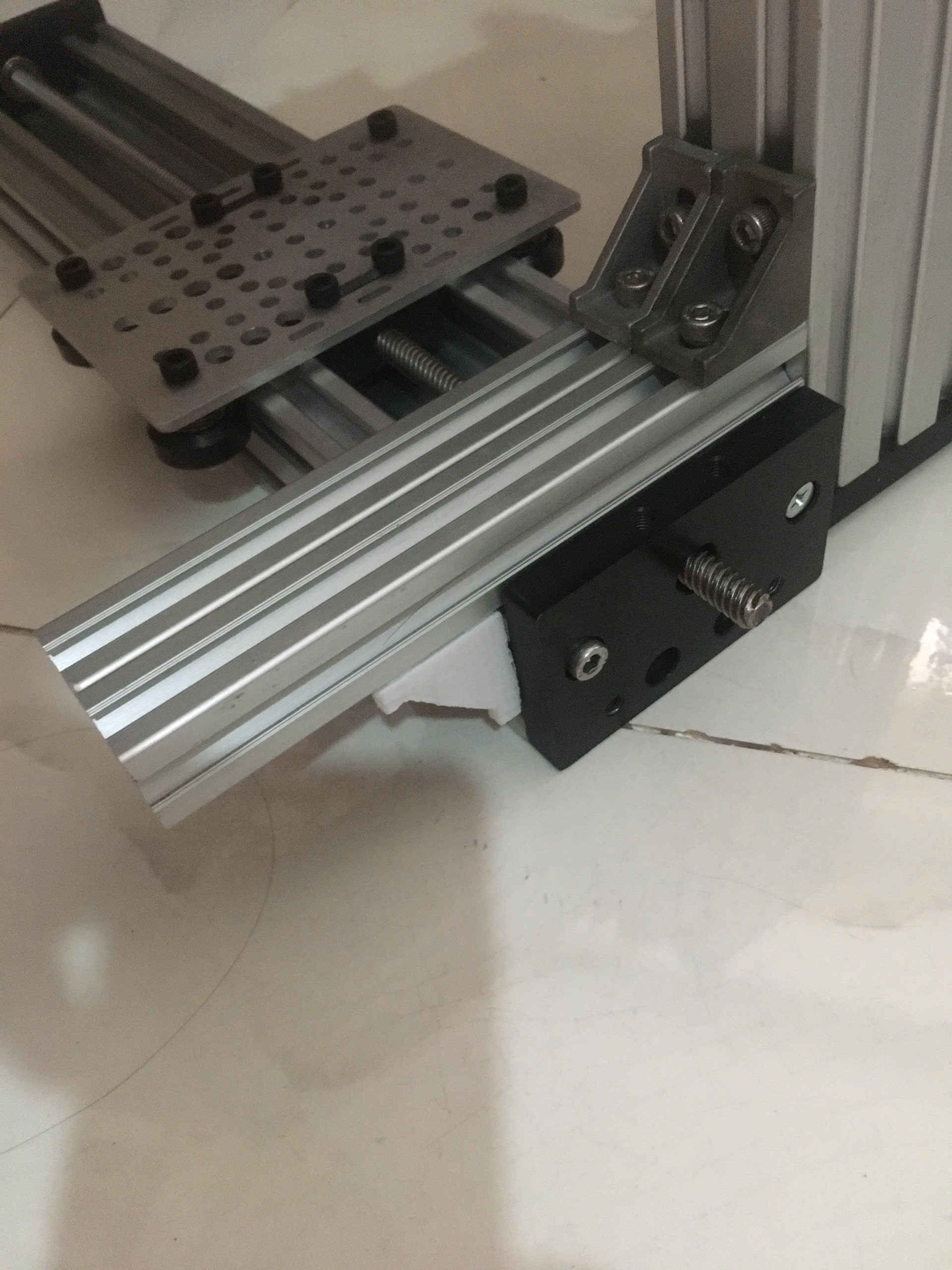
 I looked for several ways to mount the 3D printer head to the chassis and this is the option I chose, this option allows me to change the distance between the printer head and the chassis, it is more flexible.
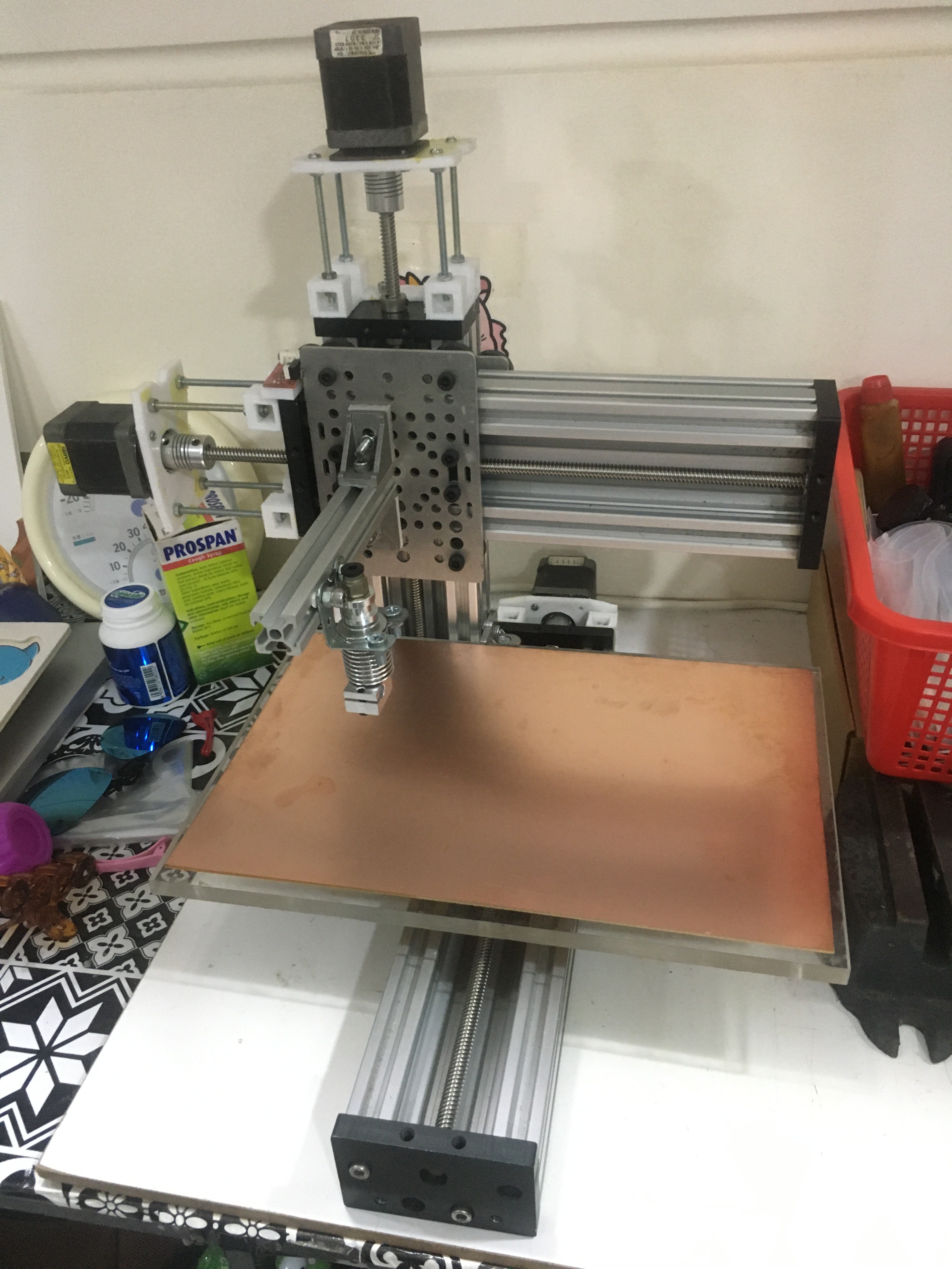

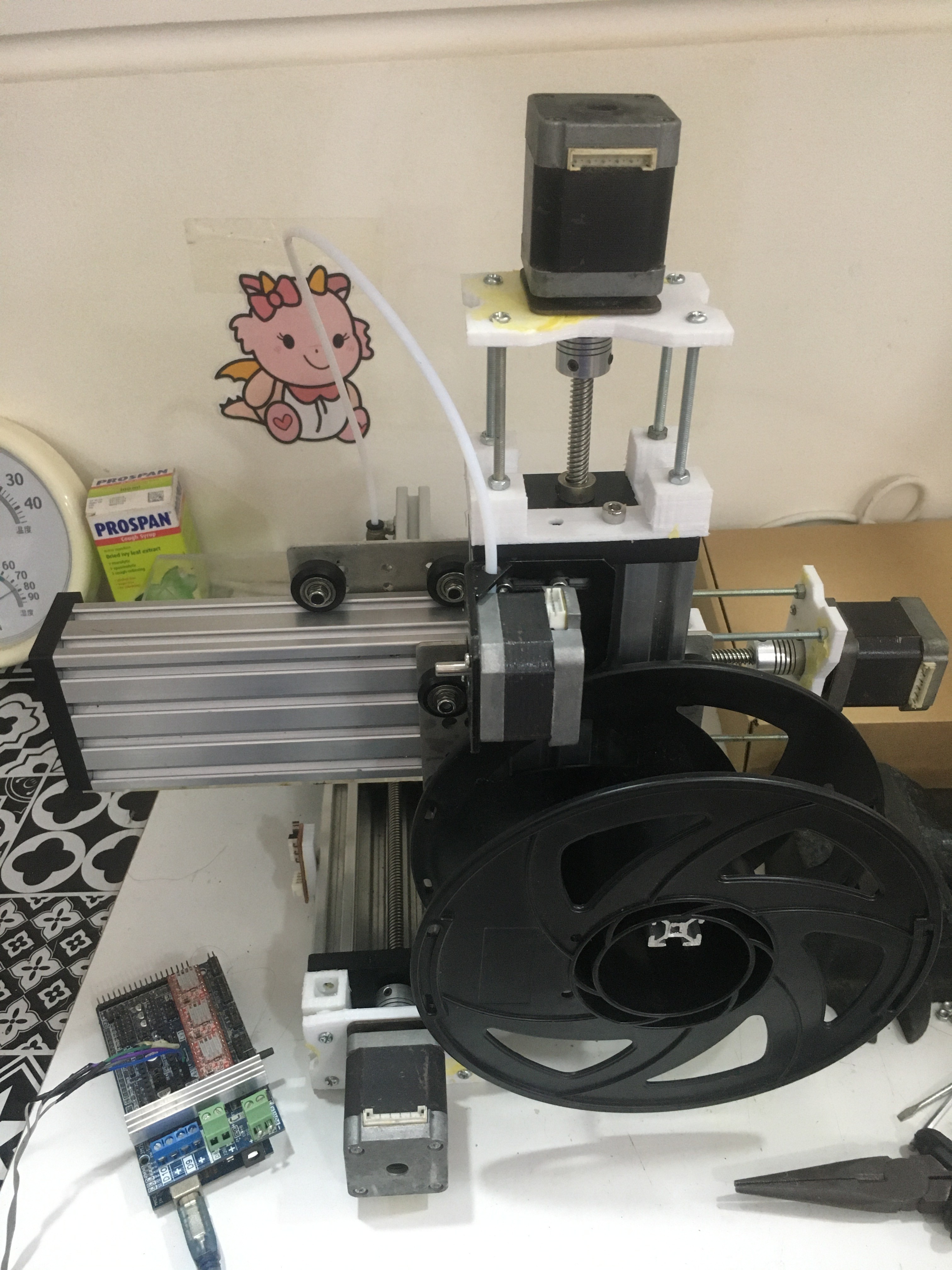
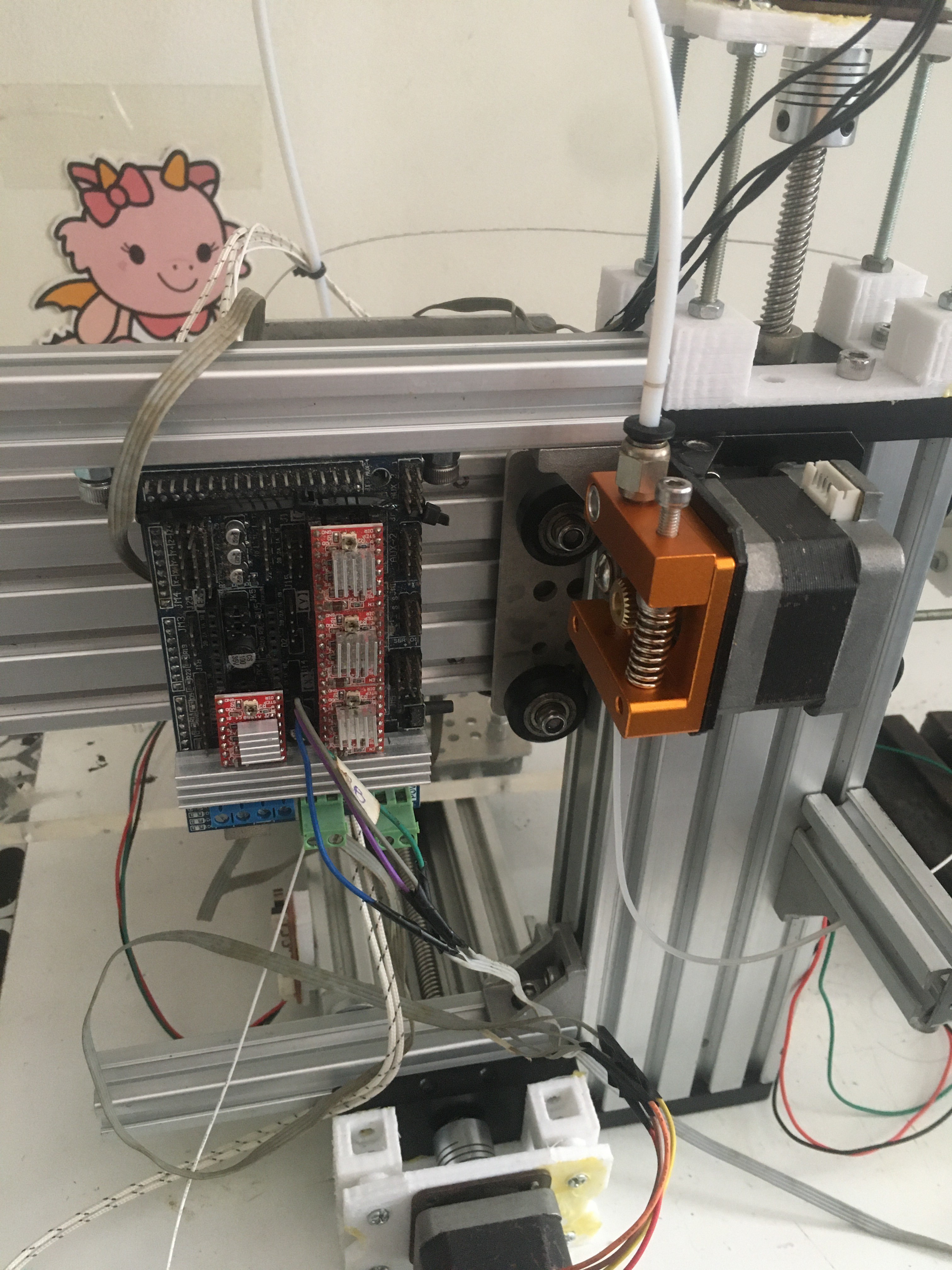
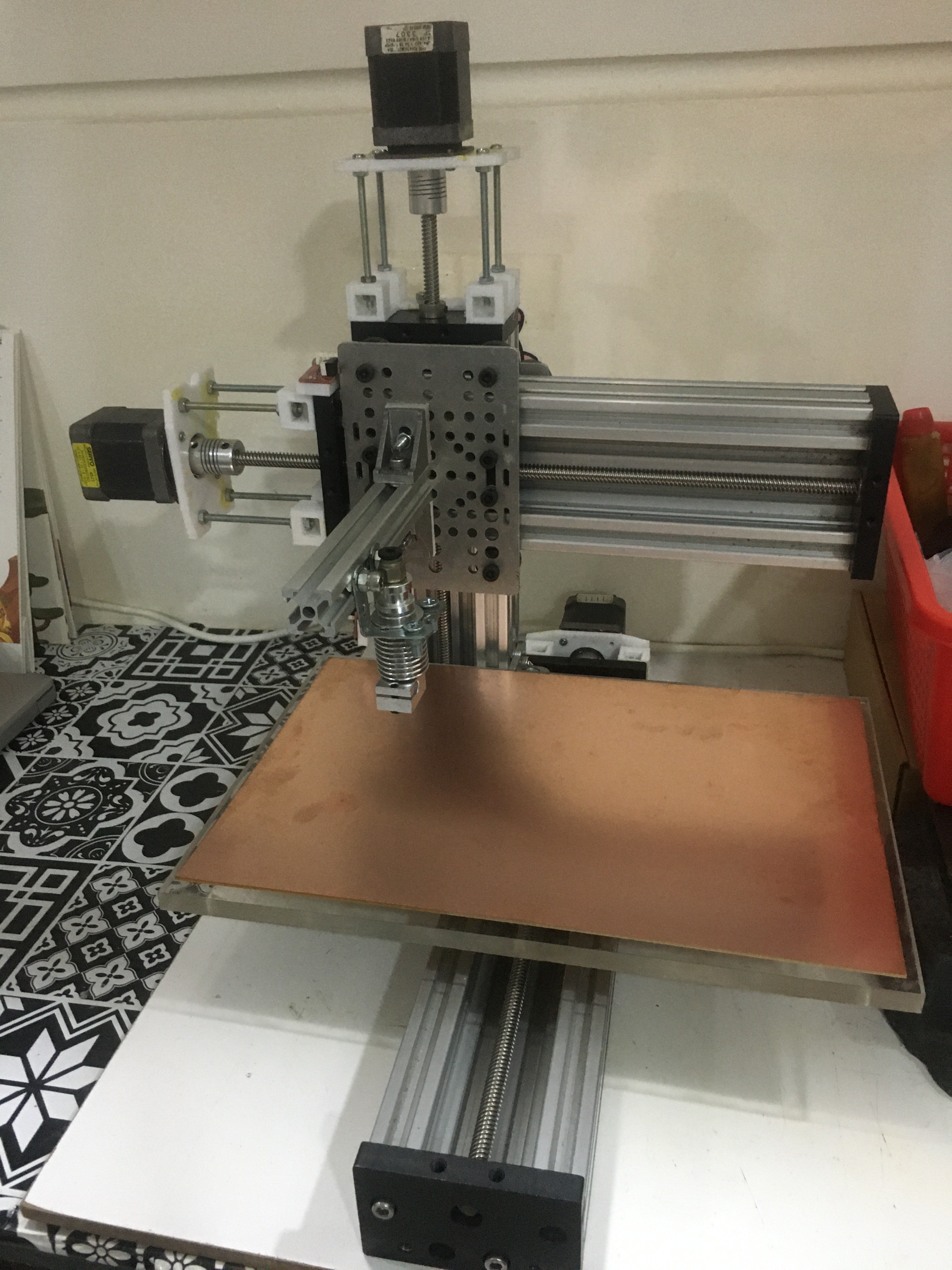 Another solution to a failed printhead mount.
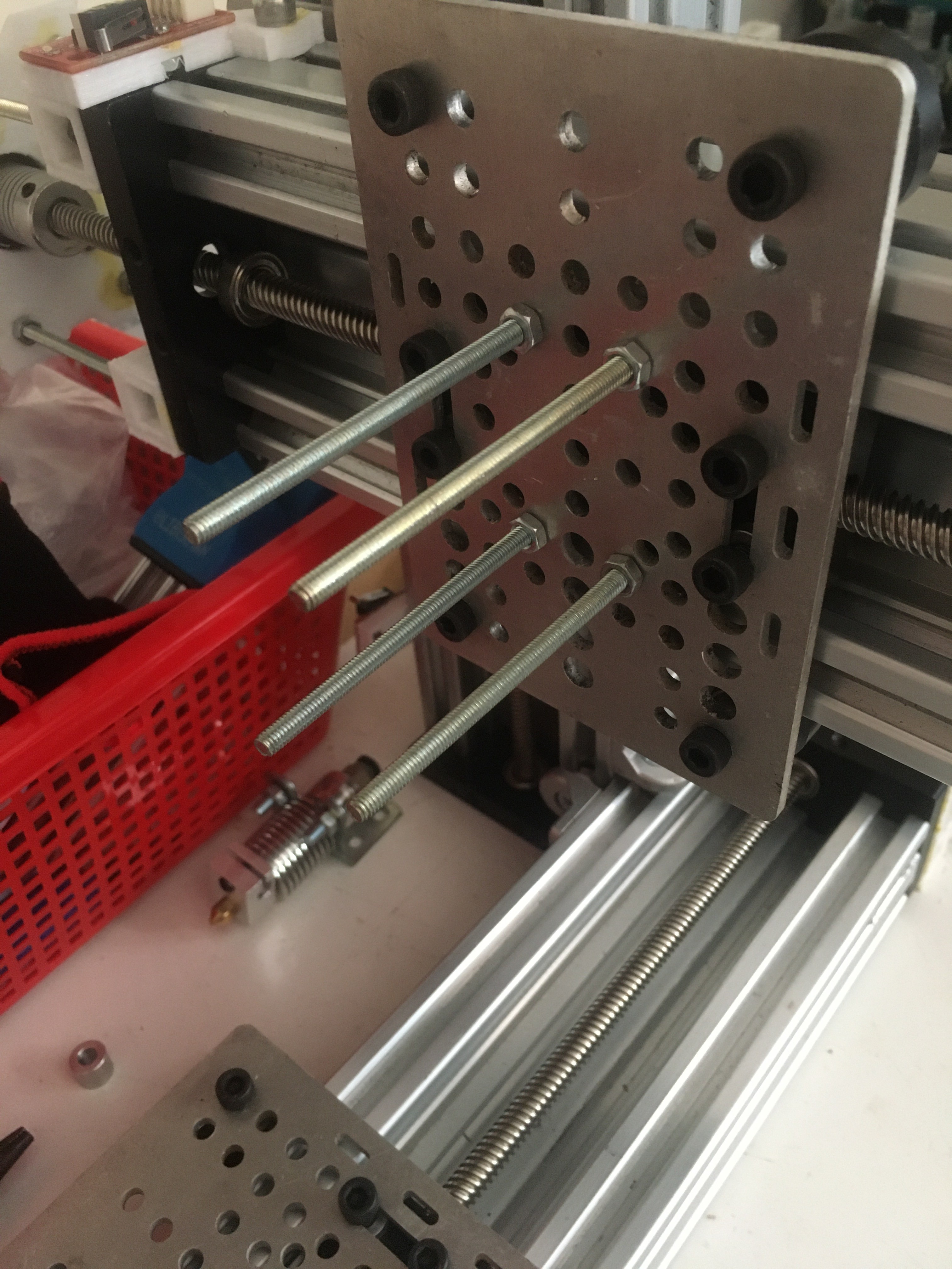
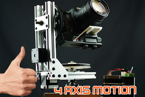
 DSLR DIY
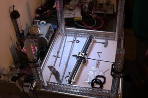
 Eviscerate Core
 Brian Brocken
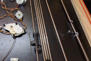
 Shawn Gorman