I started experimenting with single transistors on bread boards, building simple logic gates. The next step was to assemble the logic gates into a full adder. At first I used multiple different types of logic gates like in the following image.
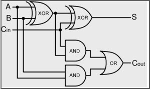
I made the circuit on a breadboard and even build a second one to hook together. They worked as expected although the leds on the output were quite dim. But I didn't let that stop me and pushed trough with creating a PCB and ordered it. After hours of assembling half the board with 72 out of 144 transistors and twice as many resistors, I plugged it in only to see that the adders worked on their own but the carry out voltage was to low to turn on the next transistor.
I created a simulation of the circuit with CircuitJS (see attached files) which showed me, that with my current architecture there are some cases where the voltage drop across the transistors is to great to turn on the next transistor.
After some research I found an alternate design that only uses NOR gates that are very simple to implement with a single transistor and three resistors per gate. This effectivly cut the total number of transistors in half and made the design actually work. This time I tested everything in with simulations before ordering and assembling a PCB.
The stunning PCBs for this project were gerenously sponsored by PCBWay. The overall quality is very good, they are made with very good tolerance and have a really good surface finish which was especially important for this project as it is supposed to be a show piece. This was my first time ordering from them and the process was very smooth and easy and the different manufacturing options are much better than with any other services I've tried in the past.
 Robin Dorst
 Alex
Alex
 Spencer
 Yann Guidon / YGDES
 LorneChrones (Nick)