-
AT Command changes
11/26/2024 at 09:34 • 2 commentsAfter comparing the SimCom radio manuals, the AT command sets are a bit different between the models. Some are the same, some replaced, others seem to have been merged and others deprecated all together. So the original firmware loaded on the arduino won't work any longer.
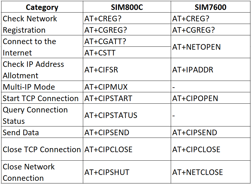
After doing some searches online, I found this very helpful post that compares the AT commands between the radios we're using.
https://iotespresso.com/sim800c-to-sim7600-network-related-at-command-changes/
This table comparing the commands is particularly helpful, as I don't have to jump around the manual to find all these commands.
![]()
If we manage to get a copy of the original code, we'll need rewrite quite a bit.
Armed with this information I should be able to test getting and sending information to a back end service from a serial terminal.
-
Radio replacement
11/11/2024 at 10:29 • 2 commentsThe original radio stopped working as Tmobile shut down it's 2G network in our area. We needed to find a replacement so that the monitors could begin reporting data again. Since the original one was from SimCom I looked for a newer model that supported 4G communications.
After some searching I found the SimCom sim7600G. It also used serial communications and ran at the same voltages as the original radio. I found a good candidate board on Aliexpress from AndGlobal for about $35. I ordered one to test it.
https://www.aliexpress.us/item/2255800037729440.html
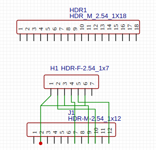
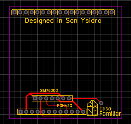
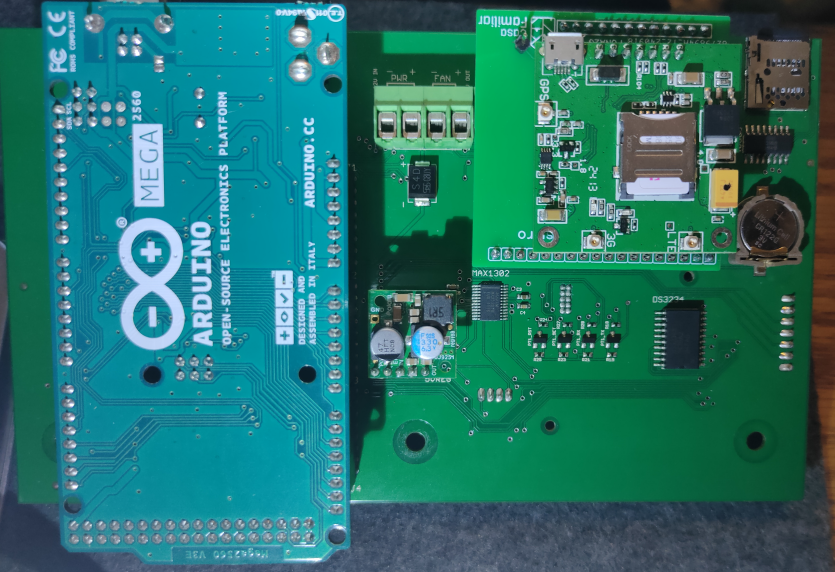
The new radio wasn't pin compatible, so In order to connect it to the main board, I had to make a simple adapter board. I chose to use EasyEDA and JLCPCB because of the ease of use and easy ordering. I just needed to cross a few wires so that it would work with the FONA pin out. In less that an hour I was able to add the headers and order the board.
![]()
![]()
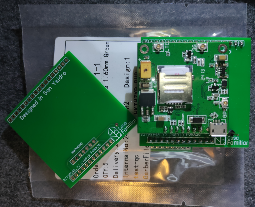
The new radio arrived in 8 days. The circuit boards arrived in about 12 days. I quickly soldered on the headers to do a test fit on the main board. The fit was tight and off by a fraction of a millimeter, since I had to roughly measure the distance on the main board, but it worked.
![]()
I was able to send test AT commands from the Arduino to the new radio. The original sim card worked and I was able to send a text message over the network. I had to provide power to the 12v connector to power the on board logic level converter.
![]()
-
Weather Woes and Water Damage
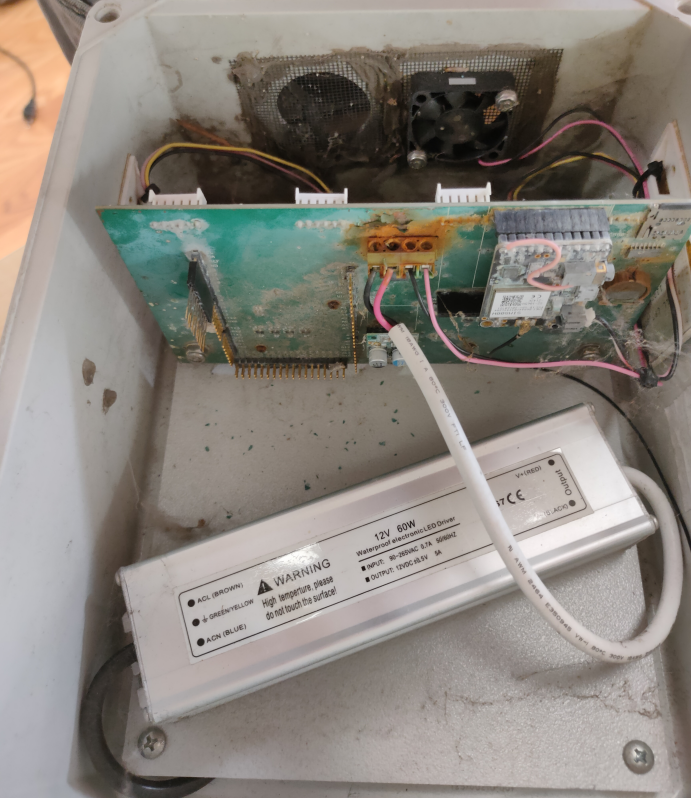
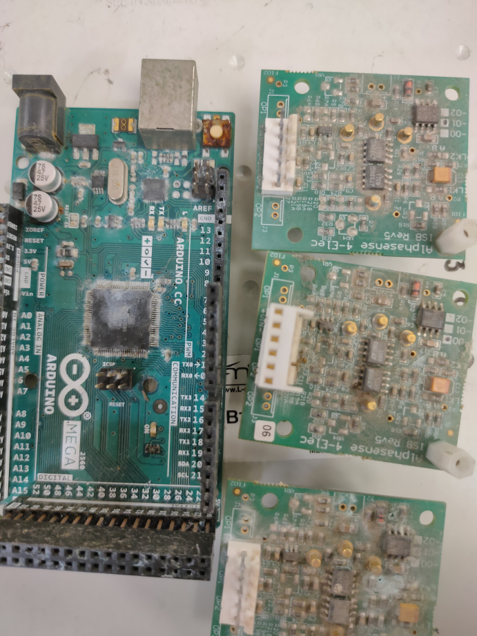
11/11/2024 at 09:18 • 0 commentsOne of the deployed monitors was unfortunately subjected to water when we had some particularly strong weather. The wind caused the tripod that was weighed down with sand bags to fall over, leaving the bottom of the case with large opening tilted up towards the rain. The pictures show the destructive results to the electronics. The fan probably helped blow in some water and fling it around until it failed.
![]()
Plenty of oxidation next to the power connector....
![]()
The arduino mega and sensor boards...
![]()
RIP...
-
Original Air Quality Monitor Hardware Inspection
11/09/2024 at 06:01 • 0 commentsThese air quality monitors were deployed around the community for 2-3 years. They were typically mounted onto a tripod on a flat roof tops, weighed down with sand bags and there was an AC power outlet available.
![]()
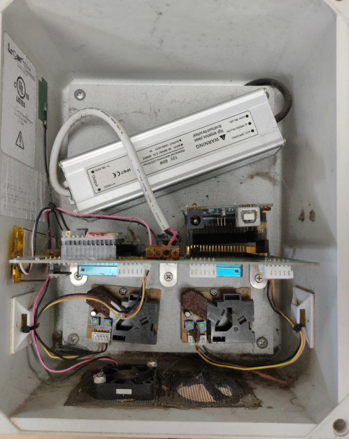
The electronics were housed in a plastic enclosure with 2 holes drilled out on the bottom side.
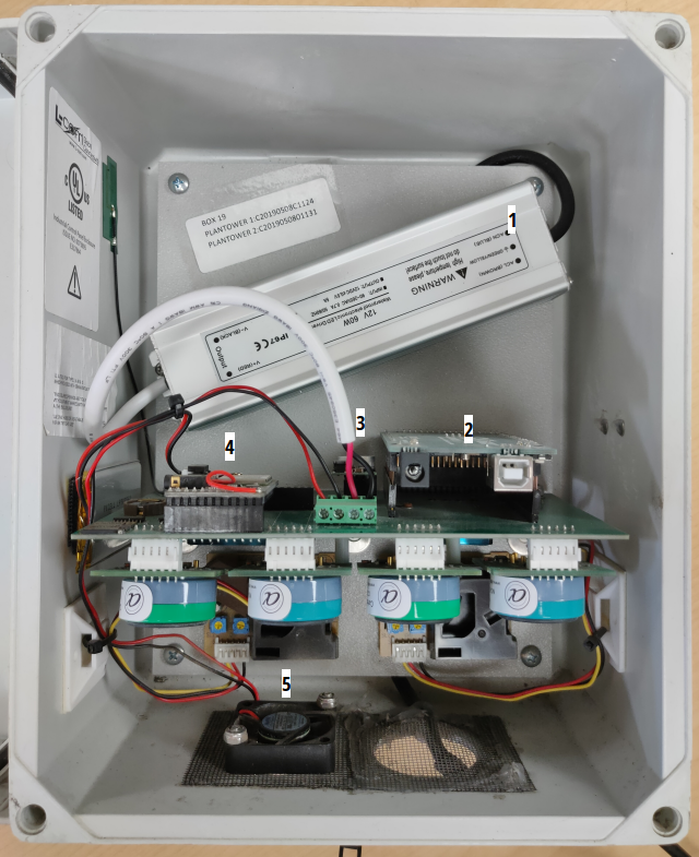
1. The AC power is stepped down to 12v DC by an LED lighting power supply that connects to the main board.
2. The brains of the monitor is the Arduino Mega 2560 connected to main board. It provides enough inputs for all the add on board and 9 sensors.
3. Pololu D24V22F5 step down voltage regulator to bring the 12v DC down to 5v DC
4. Adafruit FONA gsm quad band radio (2G) with SimCom SIM800H
5. There is 12v DC fan acting as an intake, with the second hole allowing air out. The large main board acts as an air break, keeping the air flowing over the sensors. The fan runs continuously, so it also helps keep the electronics dry. Fiberglass window screen is used to keep large debris and critters from coming into the case.
![]()
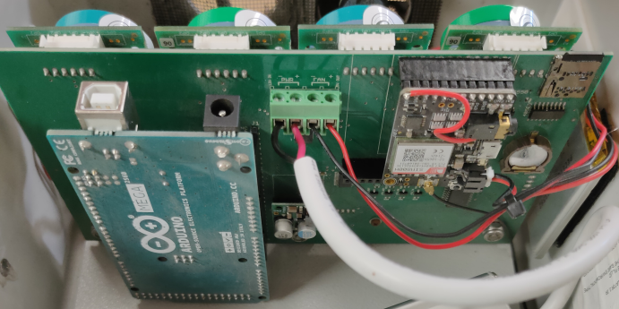
The large main board was developed by a grad student named Graeme at UW in 2019. It allows all the add on components to communicate and get power. It also has an on board RTC (DS3234), bi-directional logic level converters to the arduino, a 16 bit ADC (MAX1302) for the gas sensors and another level shifter (74HC4050D) for the micro SD card slot.
![]()
The bottom side of the main board shows the Alphasense individual sensor board for B4 series of sensors. There are two Carbon Monoxide (CO-B4) and two Nictric Oxide (NO-B4) sensors attached. These were selected to measure the difference in levels of exhaust from semi trucks. There are also two Shinyei Dust Sensor (PPD42NJ).
![]()
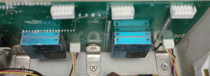
Removing the gas sensor boards reveals another set of sensors flush mounted to the main board. These are particulate matter sensors from Plantower (PMSA003) that give PM2.5 and PM10 readings. They are connected via a small header and attached with screws. There is also an Adafruit temperature and humidity sensor board (Sensirion SHT31-D) on the left. You can also see the connectors for the dust sensors and brackets that attach the main board to the case.
-
2024 SuperCon Feedback
11/06/2024 at 03:34 • 0 commentsI brought the Air Quality Monitors main board with me to SuperCon on Sunday to share information about the community project and share some of the things I recently did to restore and update the monitor hardware. My hope was that people more experienced than I with air quality sensors and cell network communications might drop nuggets of wisdom on me. There was enough interest by folks that I decided to log our project efforts and open up the possibility for suggestions. It might also help other communities with similar goals and/or hardware if they ever needed to execute an update.
I plan to share the more recent hardware updates I made as individual project logs. As well as cover the ongoing arduino firmware update to get it reporting data to a new back end.
Community Air Monitor Updates
Old Air Quality Monitor Hardware Updates by Border Community members
