-
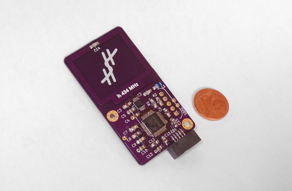
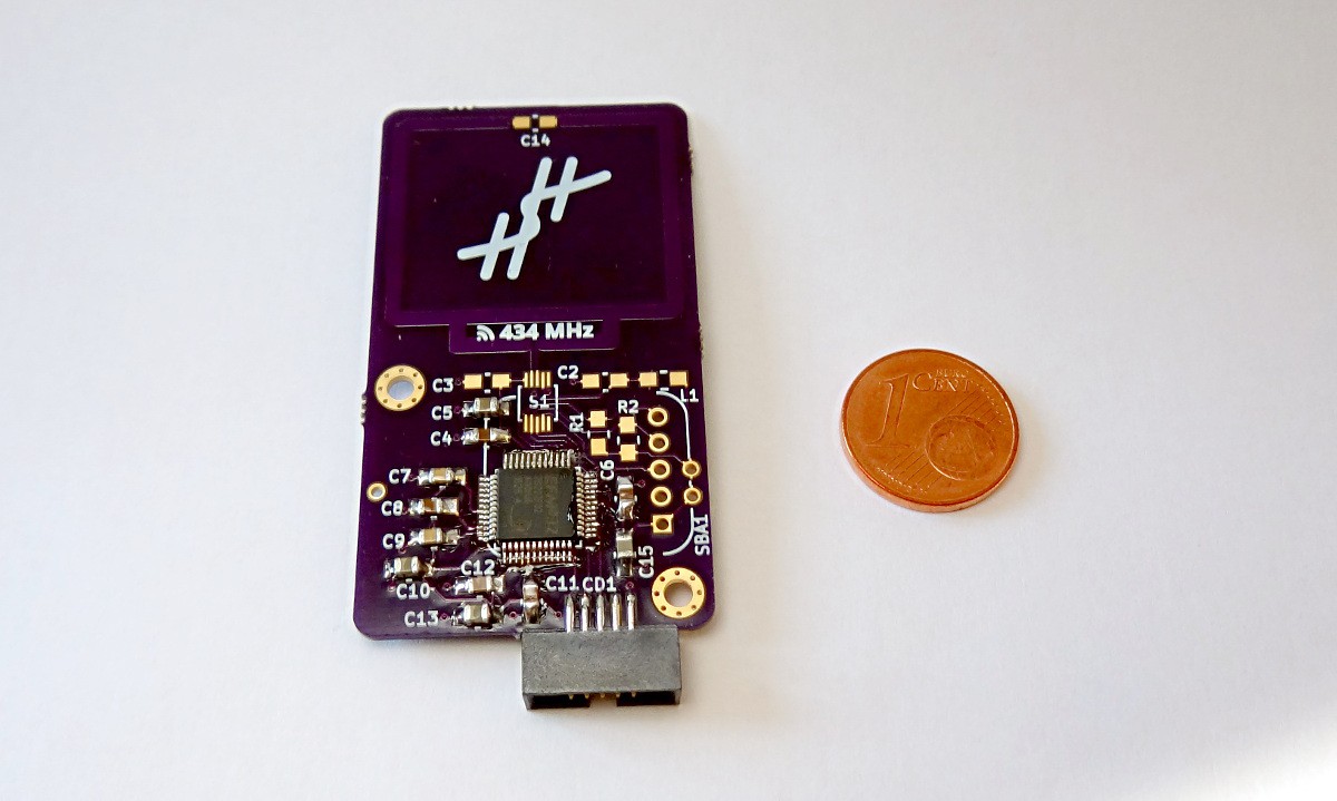
Version 1.0.1 assembled
05/13/2017 at 13:00 • 0 commentsToday, I mostly assembled one of the version 1.0.1 boards. For the time being, I left out the sensor socket and the battery. The sensor I already tested and I can't attach the battery holder as long as sensor socket is not attached.
The electrical and first MCU communication tests looked ok. Next up are the radio chip tests. Followed, of course, by the actual radio transmission test.
![]()
-
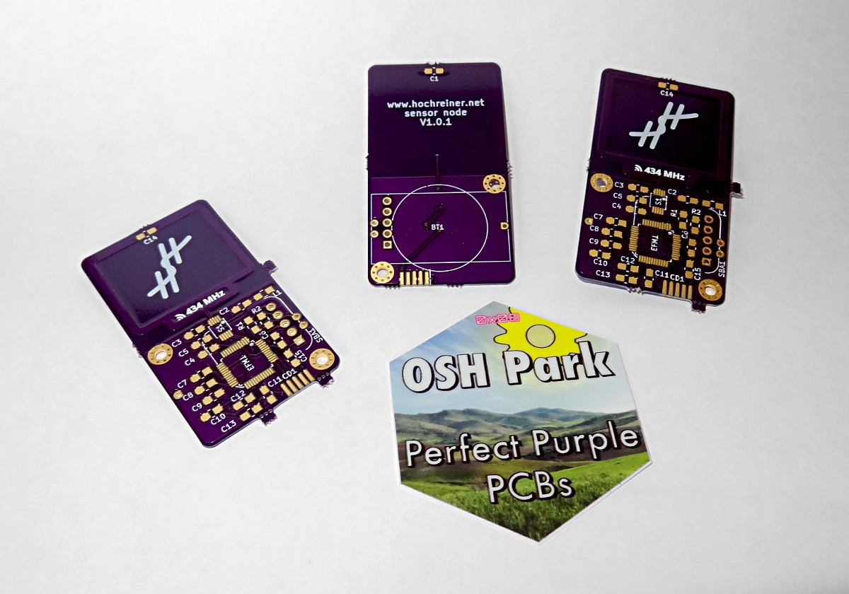
New PCBs arrived!
05/09/2017 at 19:15 • 4 commentsBig shout-out and thank you to @oshpark who did everything in his power to deliver the new version of my board as fast as possible! While I expected that the new PCBs would take 5-6 weeks to arrive, it took little more than 2 weeks. Really exceptional service.
![]()
-
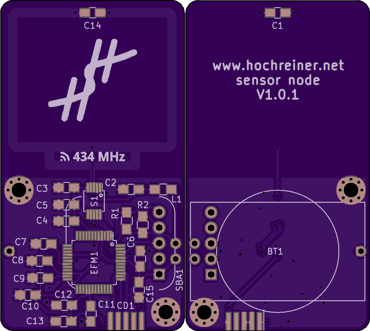
New version of the board ordered
04/22/2017 at 08:33 • 2 commentsToday, I ordered version 1.0.1 of the board from OSH Park.
With this version, I fixed the pin assignment of the radio chip, added pin 1 indicators for the MCU and the radio chip, and added more ground plane copper on the top layer.
It will probably take more than a month until I get the boards delivered, but I am really looking forward to playing with them.
![]()
-
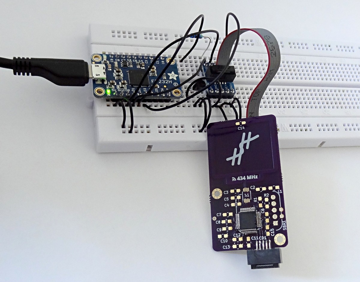
Battery operation test completed
04/17/2017 at 09:34 • 4 commentsI finally ran the last test I wanted to do with the current version of the board: the battery operation test. Since it was unclear to me from the documentation of the sensor breakout board whether it would operate normally below 3.3 V, I gave it a try. I powered the board from the CR2032, which my multi-meter claimed to be 3.05V, and looked at the measurement results in the debugger. Everything, seemed to work fine. The next step will be to order a new batch of boards with the correct pin assignment for the radio chip. I am really looking forward to seeing the full assembly work.
Background on the breakout board power confusion:
On the Adafruit description page of the breakout board it claims to work from 3-5 volts input and both 3.3V and 5V logic. However, I also had a look at the circuit diagram and the model of regulator chip (Microchip MIC5225-3.3) that has been used. This chip is rated to output 3.3V with a dropout voltage of typically about 300mV at full load. My confusion was mainly that I thought that below about 3.3V (actually rather 3.6V) it would not work. This did not fit with the documentation and also did not reflect what I experienced powering the breakout board from a 3.3V source. Now that I tried with a 3V source and had another read of the data sheet, I think the more accurate interpretation is that below 3.6V the regulator chip rated for 3.3V cannot provide the 3.3V anymore. Even so, it does not go to zero straight away. There is actually a nice graph in the data sheet showing the output voltage remains about 0.5V below the input voltage down to about 2.3V. Only then it drops to zero. Since the sensor chip works down to 1.9V, everything should work out just fine down to a battery voltage of about 2.4V.
-
Reading sensor values
04/15/2017 at 07:44 • 0 commentsReading the sensor values turned out to be pretty straight forward. The emlib provides a nice abstraction for handling I2C communication. Furthermore, there are a few examples that can be found around the web. In the first iteration, I took the simplest approach by using blocking mode (clock stretching) requests. I think that I could gain some efficiency in setting up DMA driven I2C communication, but I figured it might be better to start simple.
The actual code can be found on GitHub. I used GDB to load and debug the code on the MCU. Having only worked with 8-bit AVR, I really enjoyed being able to debug the code directly on the MCU. Although I cannot debug the code right in the IDE, it is still so much better to have GDB session with full access to memory and breakpoints than trying to debug code using printf and blinking LEDs.
For completion, here is a condensed version of the GDB session:
I started OpenOCD in one terminal:
$ openocd -f sensor-node.cfgThen, I opened a second terminal to start GDB:$ arm-none-eabi-gdb sensor-node.axf (gdb) target remote :3333 (gdb) monitor reset halt (gdb) load `sensor-node.axf' has changed; re-reading symbols. Loading section .text, size 0x166c lma 0x0 Loading section .ARM.exidx, size 0x8 lma 0x166c Loading section .data, size 0x74 lma 0x1674 Start address 0x164, load size 5864 Transfer rate: 12 KB/sec, 1954 bytes/write. (gdb) b main.c:50 (gdb) c Continuing. Breakpoint 1, main () at ../src/main.c:50 50 for(volatile long i=0; i<100000; i++) (gdb) p ret $1 = i2cTransferDone (gdb) p/x rx_buffer $2 = {0x7b, 0x7e}Which yielded the plausible value of about 54% relative humidity.
-
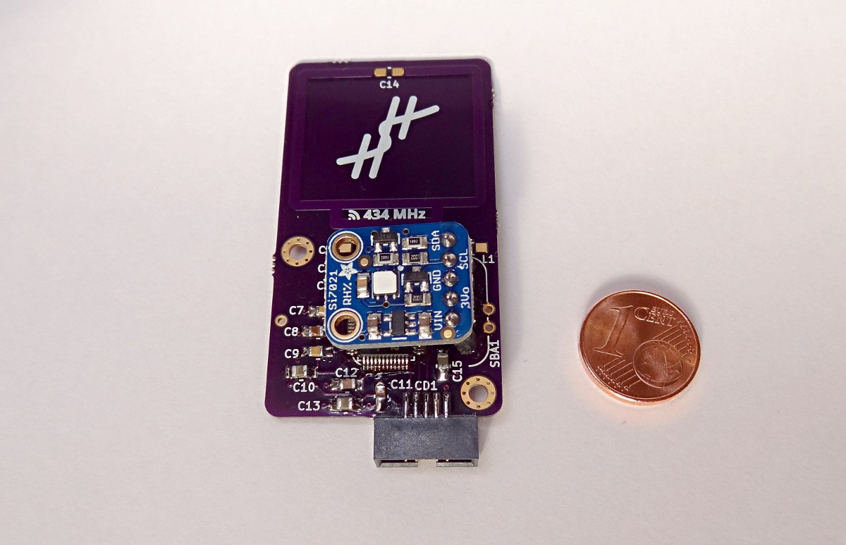
Sensor added
04/14/2017 at 08:54 • 0 commentsI just added the I2C pull-ups and the sensor socket to the board. For the time being, this is the final state of this version of the board. There is no point in adding the radio components, as the pin assignment has to be corrected. However, I can attach the sensor and test the communication between the sensor and the MCU now.
![]()
-
First program
04/09/2017 at 17:28 • 2 commentsToday, I learned an interesting lesson: decoupling capacitors matter.
For the last few days, I had been stuck with a problem: reading from the MCU worked, but flashing a new program always failed. I started going through all possible causes (OpenOCD configuration, physical connections, ...), but I could not find the cause of the problems. Then I remembered reading recently that the decoupling capacitors are not only there to cope with ripples in the power supply, but also to smooth out the varying power demand of the MCU. Therefore, I decided to add the decoupling capacitors and give the board another try:
> program sensor-node.hex verify
target halted due to debug-request, current mode: Thread
xPSR: 0x01000000 pc: 0x00000164 msp: 0x20001000
** Programming Started **
auto erase enabled
wrote 3072 bytes from file sensor-node.hex in 0.173291s (17.312 KiB/s)
** Programming Finished **
** Verify Started **
verified 2888 bytes in 0.036685s (76.879 KiB/s)
** Verified OK **
Fortunately this time everything worked without errors.
Coming from a background of working with Atmel 8-bit chips, which work quite well without decoupling, the solution to this problem was not all that obvious to me. However, I think it was a valuable lesson in building robust designs.
![]()
-
Wrong pin assignment
04/08/2017 at 16:36 • 0 commentsAs I was getting ready to solder the radio chip (Si4012), I realized that the pin assignment for this chip was wrong. This is - obviously - not ideal. While the problem is easily fixable and the financial hit of ordering new boards is bearable (< 15 EUR), the additional delay (3-5 weeks) is quite severe.
However, there are still a few things I can do with the boards as they are now:
- check that programming the MCU works
- check the communication with the sensor
- check that the sensor works with the voltage the battery is able to supply
-
MCU communication successful
03/12/2017 at 14:25 • 0 commentsI just tested the communication of the MCU with OpenOCD. Judging from the output I received, I would say it was a success. Normally that would not really be worth mentioning. However, as this is an architecture - and also a toolchain - that is new to me and the first time I soldered this kind of package, I could not take the success of this step for granted. Now that the basics seem to work, I can move on to populating the rest of the PCB and writing some test programs.
![]()
-
MCU ready for testing
03/11/2017 at 09:59 • 3 commentsI just finished soldering the EFM32ZG222 and the SWD connector on the board. From my understanding, I would be better to also place the decoupling capacitors, but I think I might try and flash some test program on the MCU as it is right now. The soldering process actually went about as smooth as I hoped it would. Aligning the chip was a bit tricky, but I expected as much. Now, I am looking forward to actually using the chip.
![]()
sensor node
a learning project to gain experience with RF design and the ARM Cortex M0+ platform