 Cora
CoraGoals:
- Easy-to-build.
- Scalable.
- Modular.
- Looks like it could be installed into a mecha cockpit.
A modular, hot-swappable, patchable, Eurorack-compatible simrig buttonboard system with a low barrier-to-entry
Already have an account? Log in.
To make the experience fit your profile, pick a username and tell us what interests you.
Goals:
EurorackButtonBoard-V1.zipVersion 1: It's a bit jank, but it works!x-zip-compressed - 5.10 MB - 03/06/2025 at 07:31 |
|
With version 1 done and dusted, I had some time to sit and use it. And what I found was a lot of the buttons and such were too close together!
This was actually a huge relief, because as I was designing the modules, I was trying to cram them in as close as I physically could to avoid potentially having too much wasted space. So knowing I have the opposite problem means I can start to be creative with how I lay things out.
One of the other things I noticed, trying to use the buttons and switches, is that the case is too light! What I mean by this is, with it just sitting in a case on my desk and not affixed to anything, trying to press some of the larger switches, or move the sliders, is a lot harder than it should be. I have to sort of wedge my hand against the case in order to get enough leverage to move the toggle switches.
Something else I noticed was that it doesn't quite have the same "look" to it that a lot of military/HOTAS systems have.
I can solve all of these problems at the same time.
I was browsing Etsy, of all things, and came across some small handles for hand-made tables and drawers. It was clearly just a drop-shipper, but it got the idea in my head: little handles for each part! That way, I can have the leverage I need to press the buttons easily, and it will look more like the military/HOTAS systems I've seen around.
So I went onto AliExpress, and started searching. I found lots of u-shaped rod handles that fit the bill, but only one or two sellers that were selling ones small enough to fit onto a 1U module, and even then only if I got creative with it (links in the Components section).
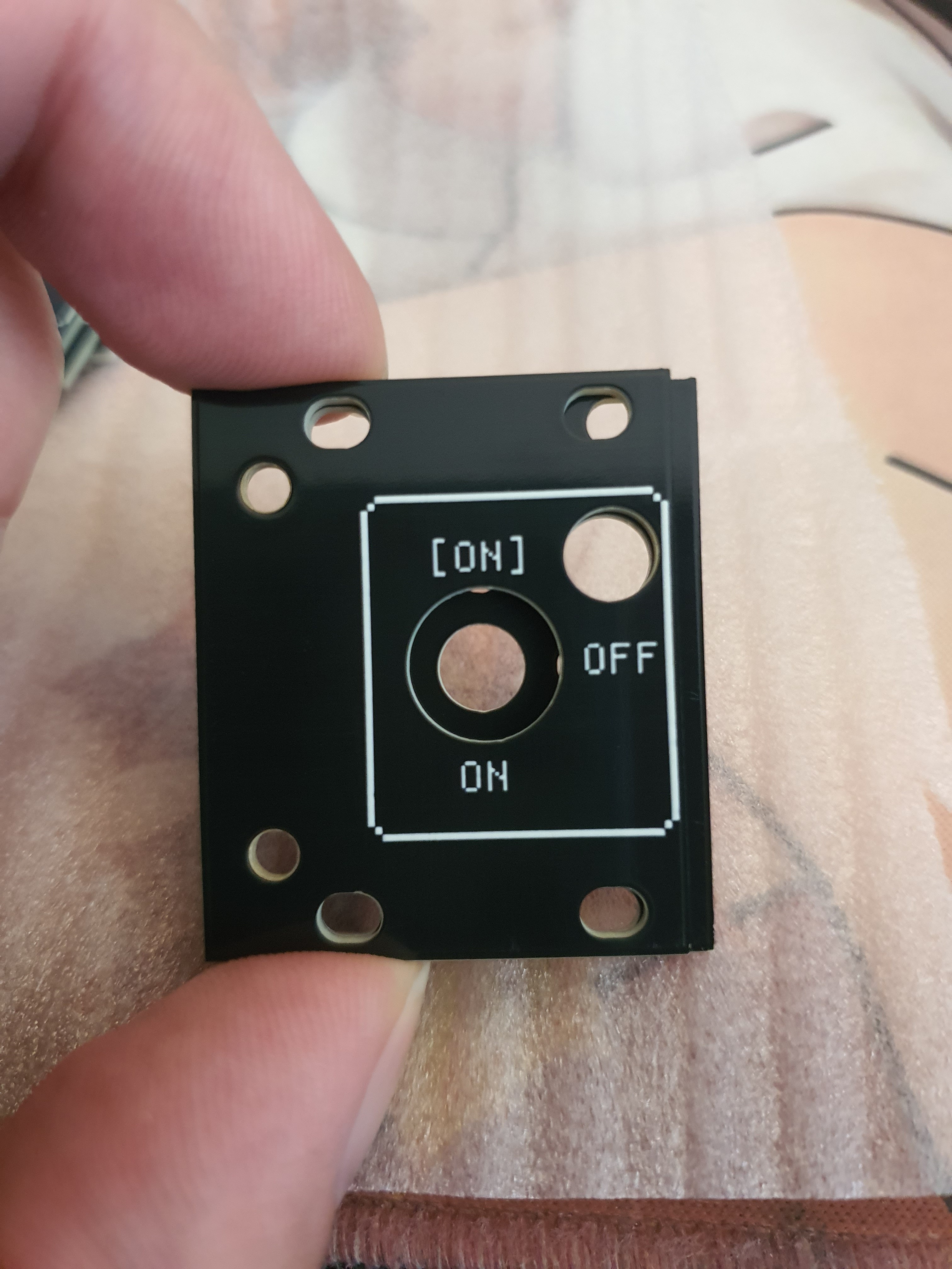
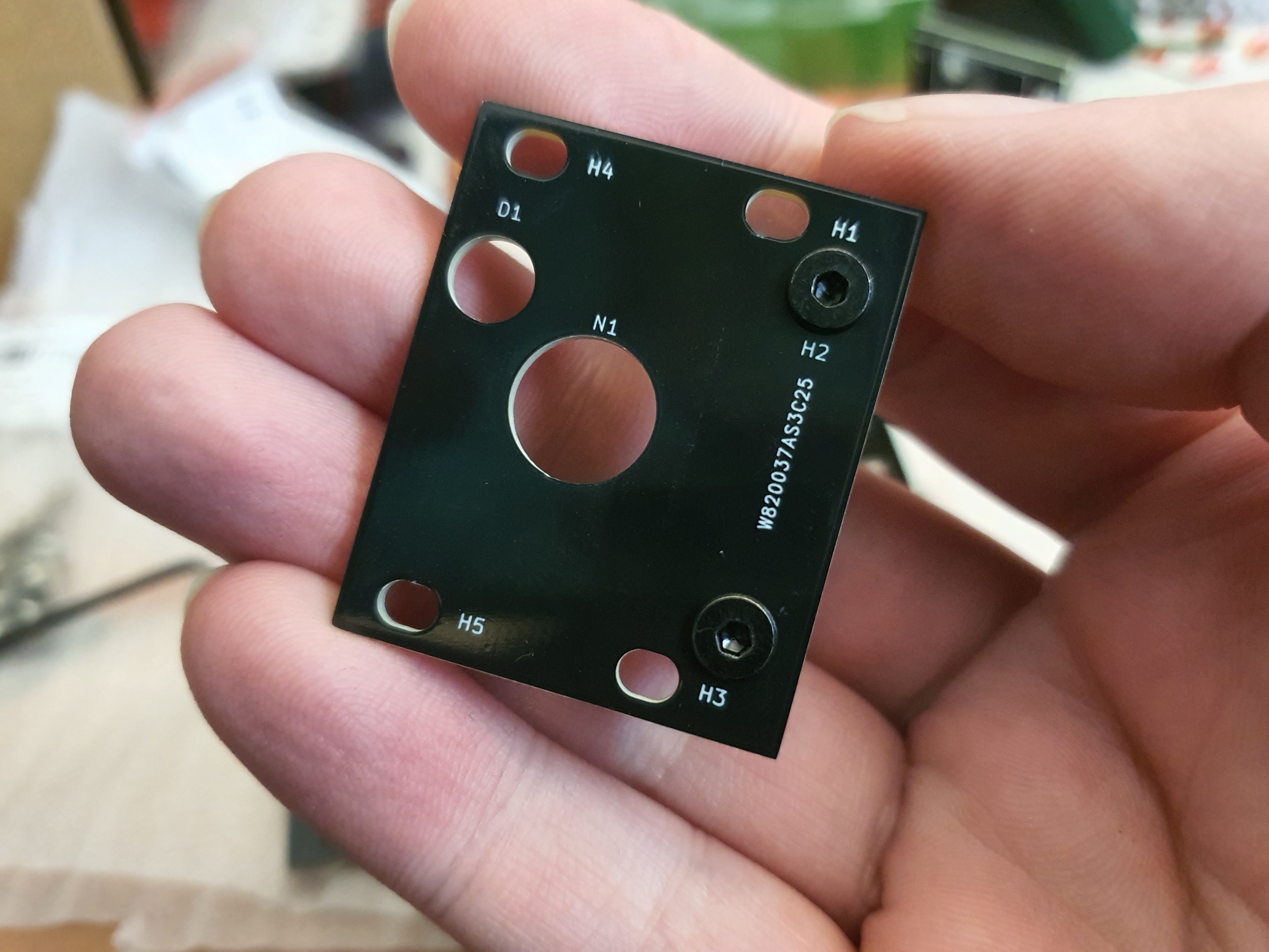
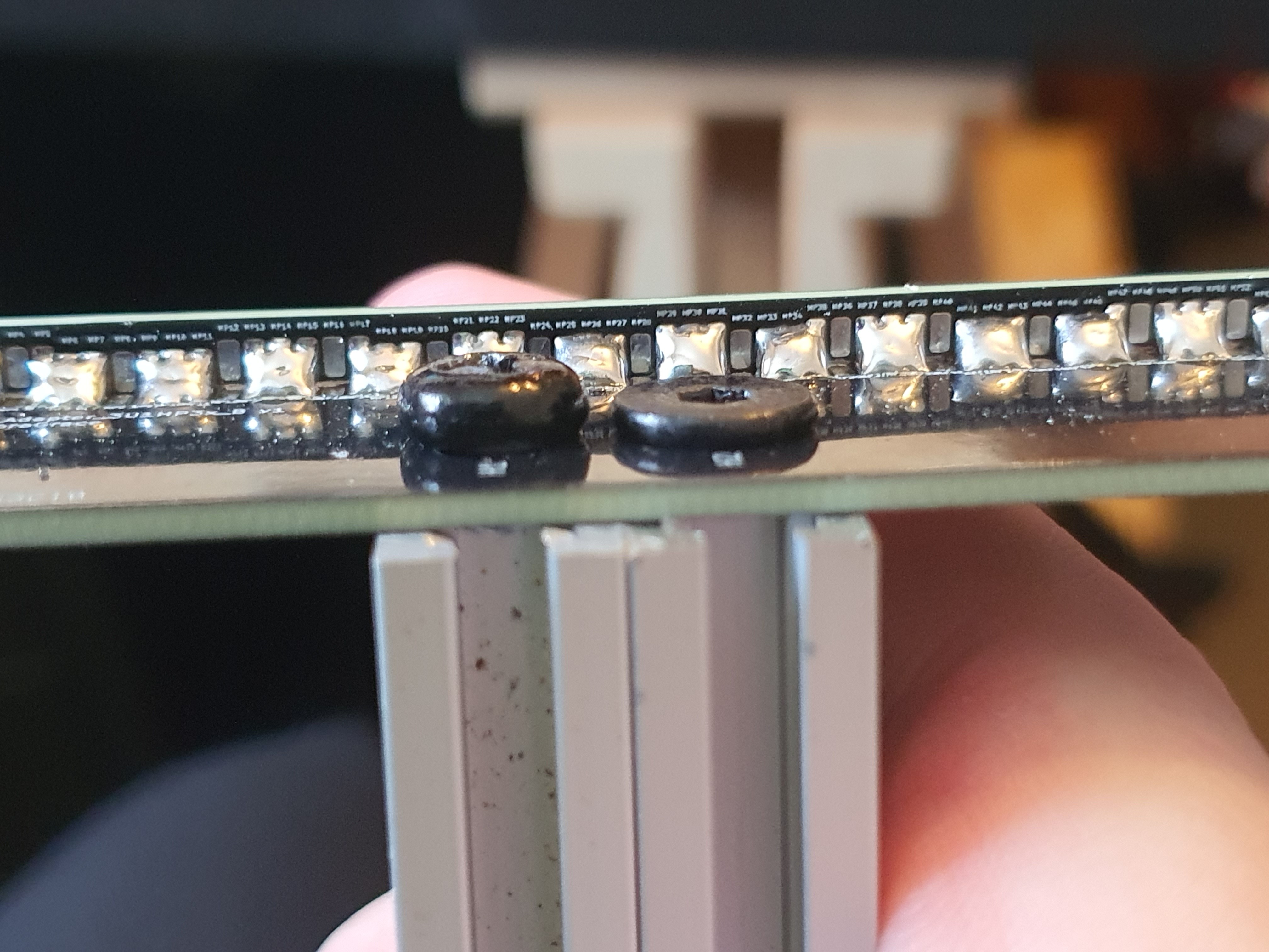
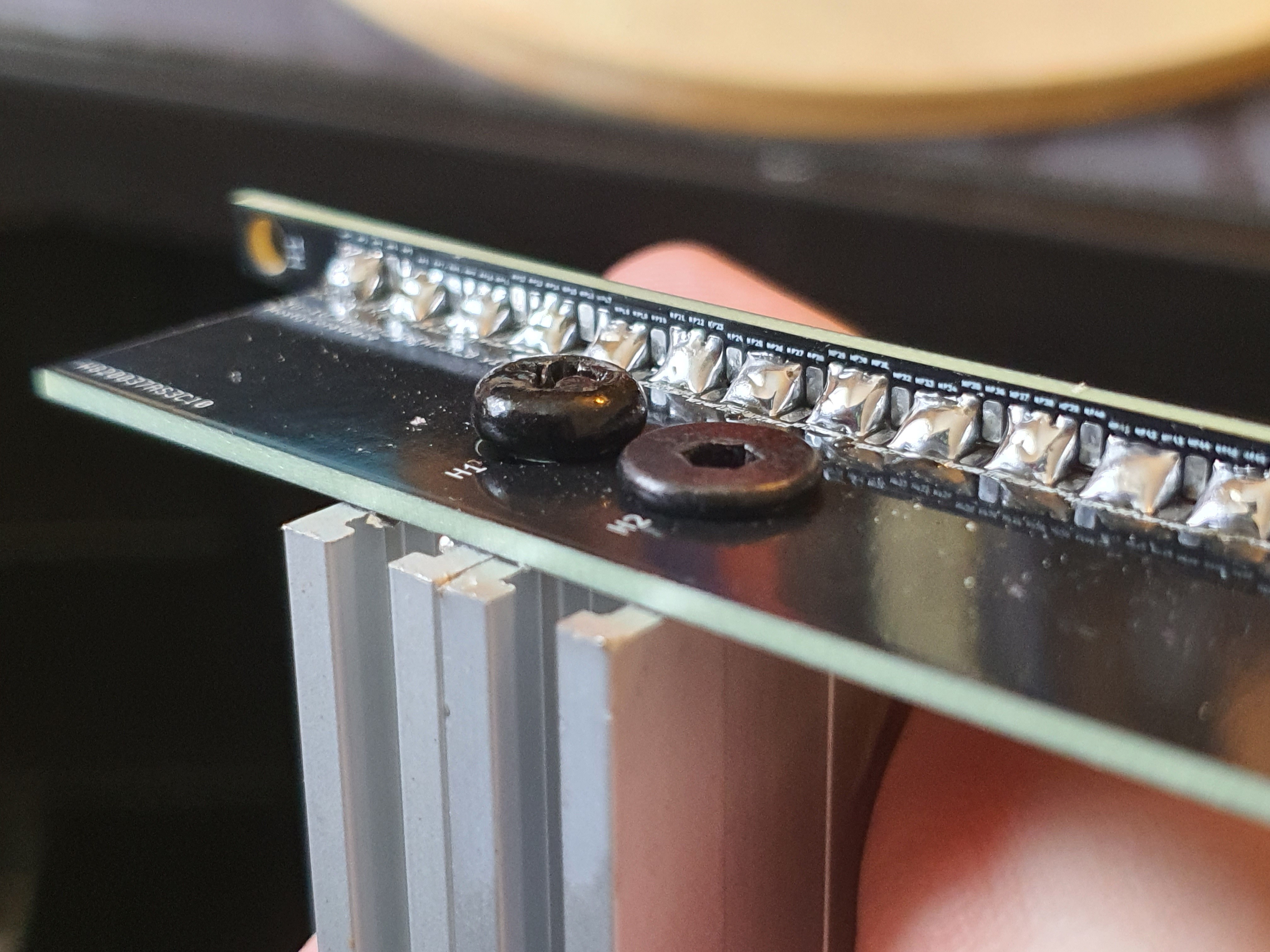
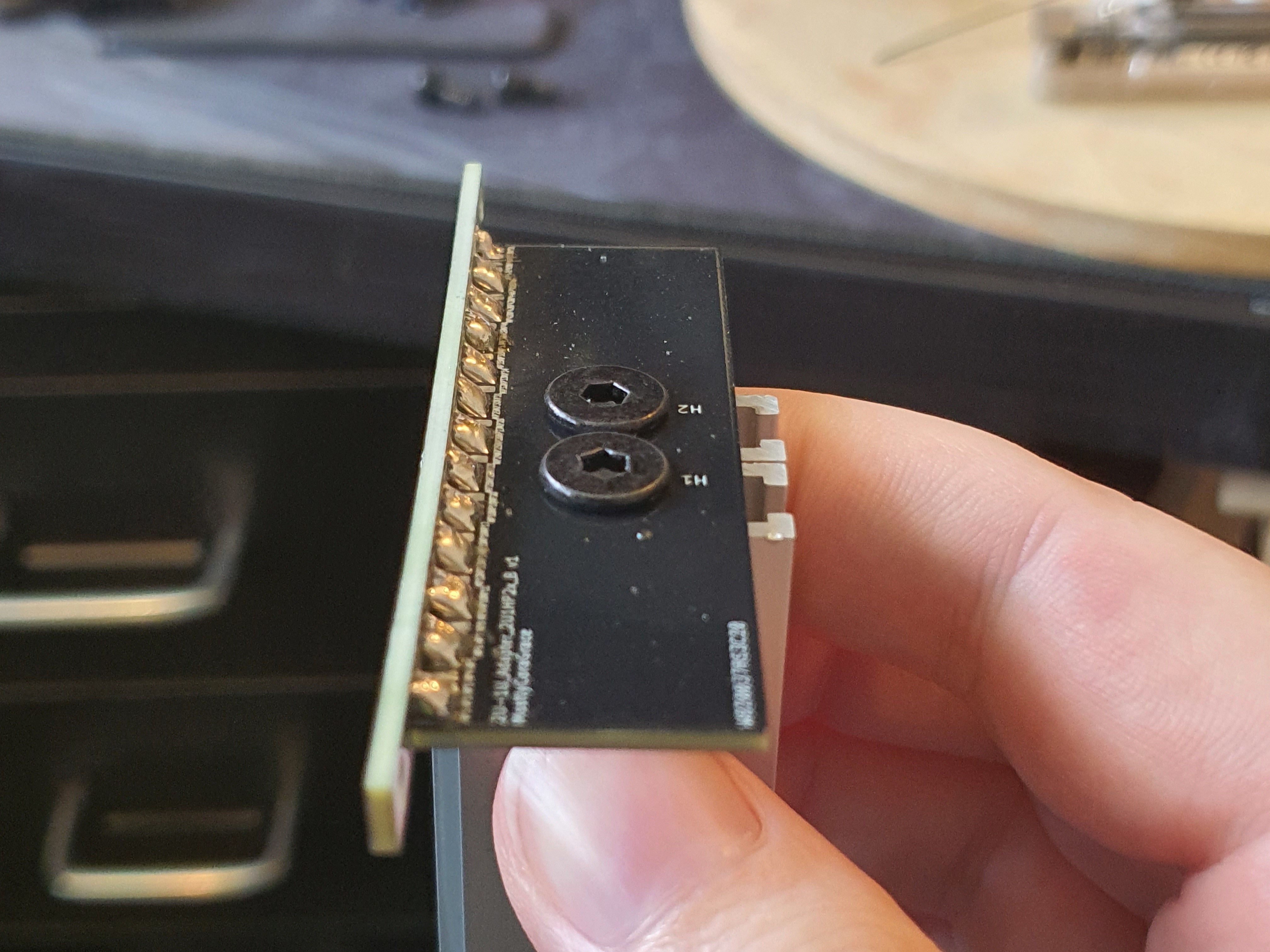
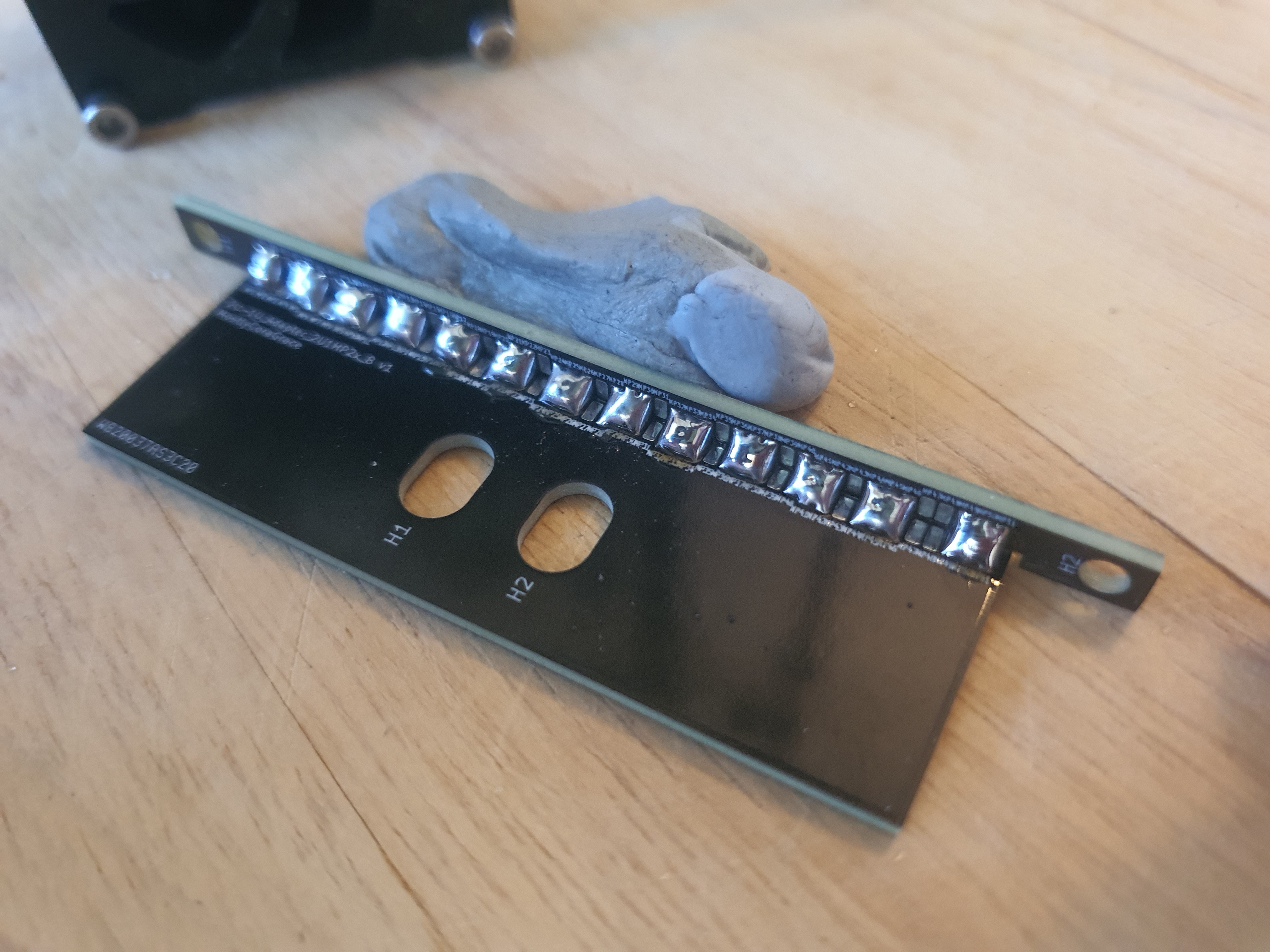
The problem is that the handles have a 25mm spacing between the M3 screw holes, and I only have 22.5mm to work with between the rails of a 1U module. So I started to brainstorm; what if I got 3D with it? Took some of the sandwich keyboard knowledge I have, combined it with a lil' bit of 3D printing know-how, and designed *two* PCBs that stacked together? One of the PCBs would attach to the handle, and the PCB beneath it would have a matching hole for the screw to fit in. The height of the bottom PCB would be enough to hide the screw, if I used the thin screws I used for attaching the Eurorack rails to my custom adapters, and it would let me play with a bit of depth as I could vary the PCB footprints such that their height differences could create some interesting vertical detail.
This is what I came up with:
It was at about this time that Liam, my lovely PCBWay representative, got back to me asking about future projects, since he seemed so happy with the previous logs I've made here, and I decided to ask about another sponsorship for this version 2. I threw the PCBs I designed into the fancy PCB Way button in KiCAD that I love so much (seriously, it's so handy), and sent them his way.
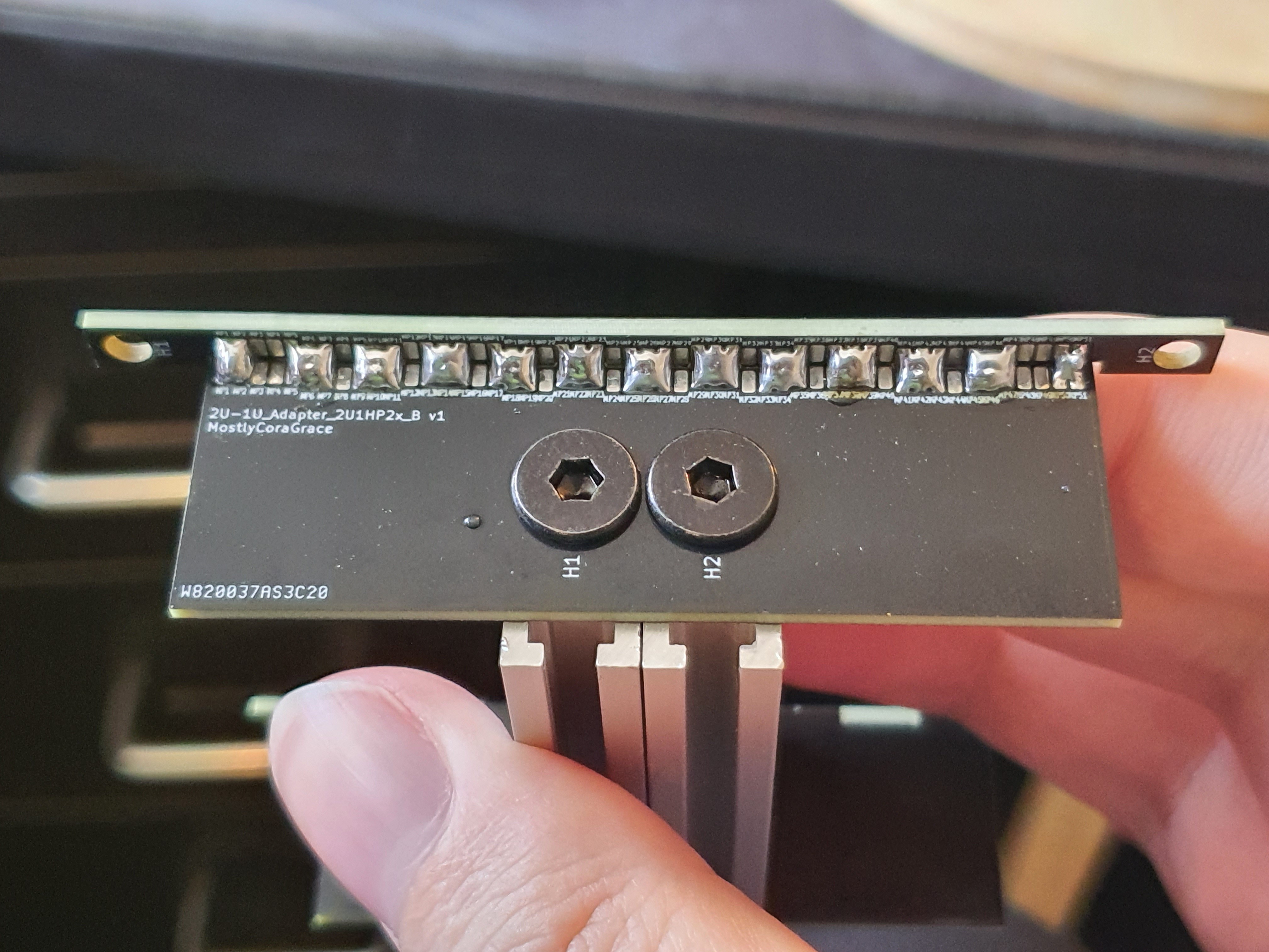
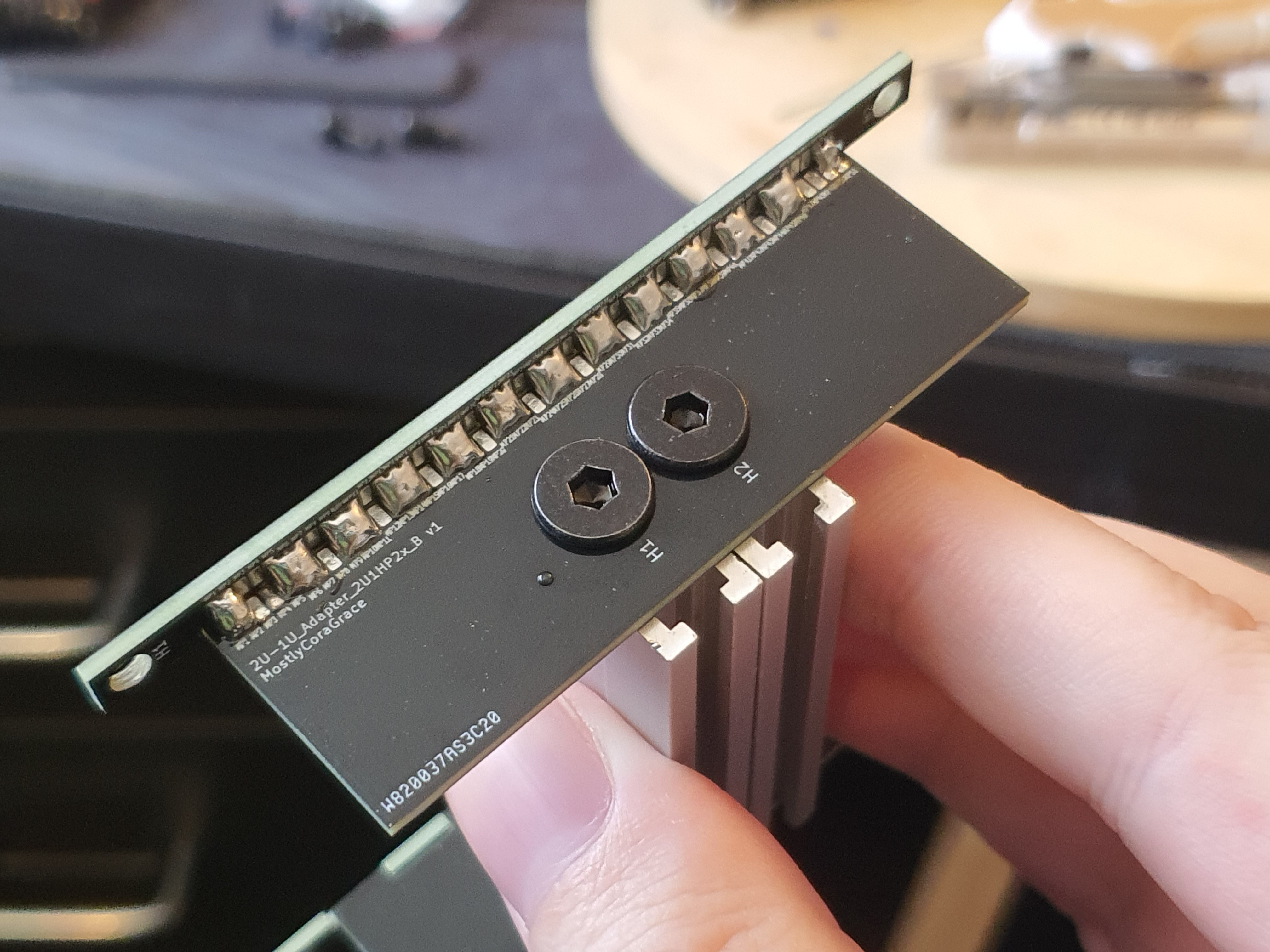
Less than the estimated time later (an unexpected, but not unwelcome surprise!), the PCBs were at my door, and look! aren't they beautiful!
I did notice that top-right screw hole doesn't match, so I checked the PCB designs and indeed they were misaligned. Entirely my fault!
I will have to keep this in mind as I design more modules, as now I have two PCBs that I need to keep aligned together, or things will start to get really difficult and annoying very quickly.
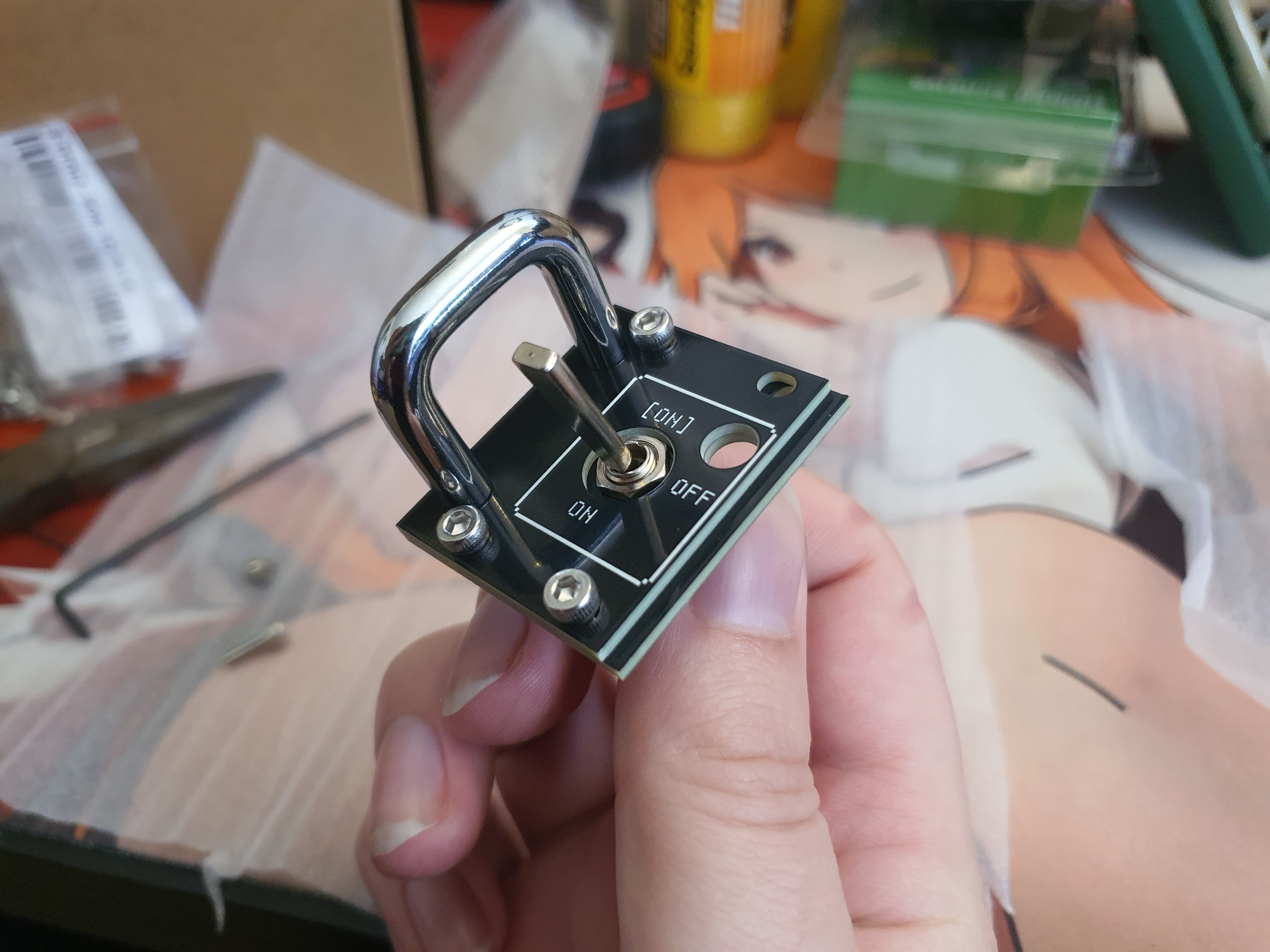
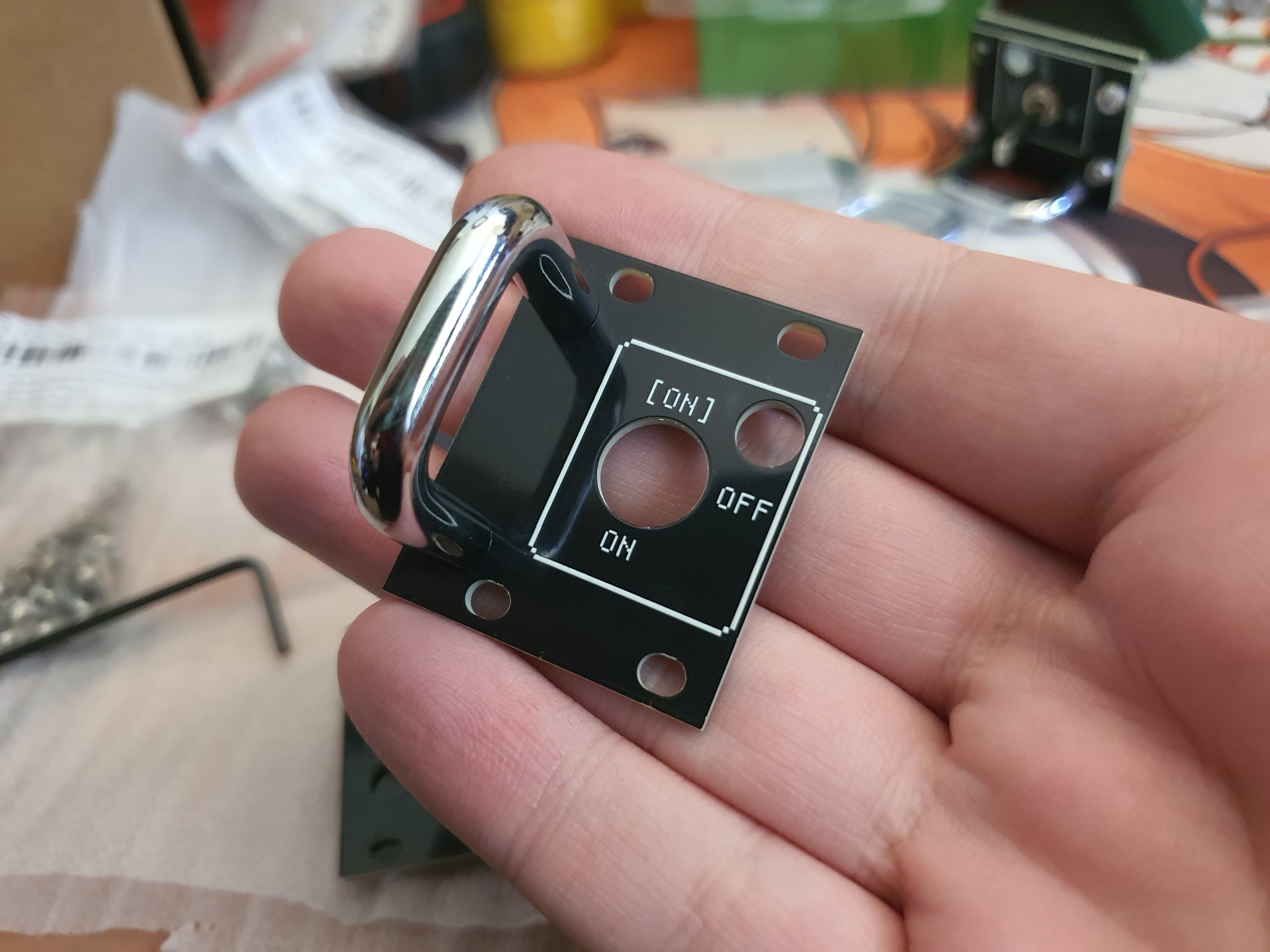
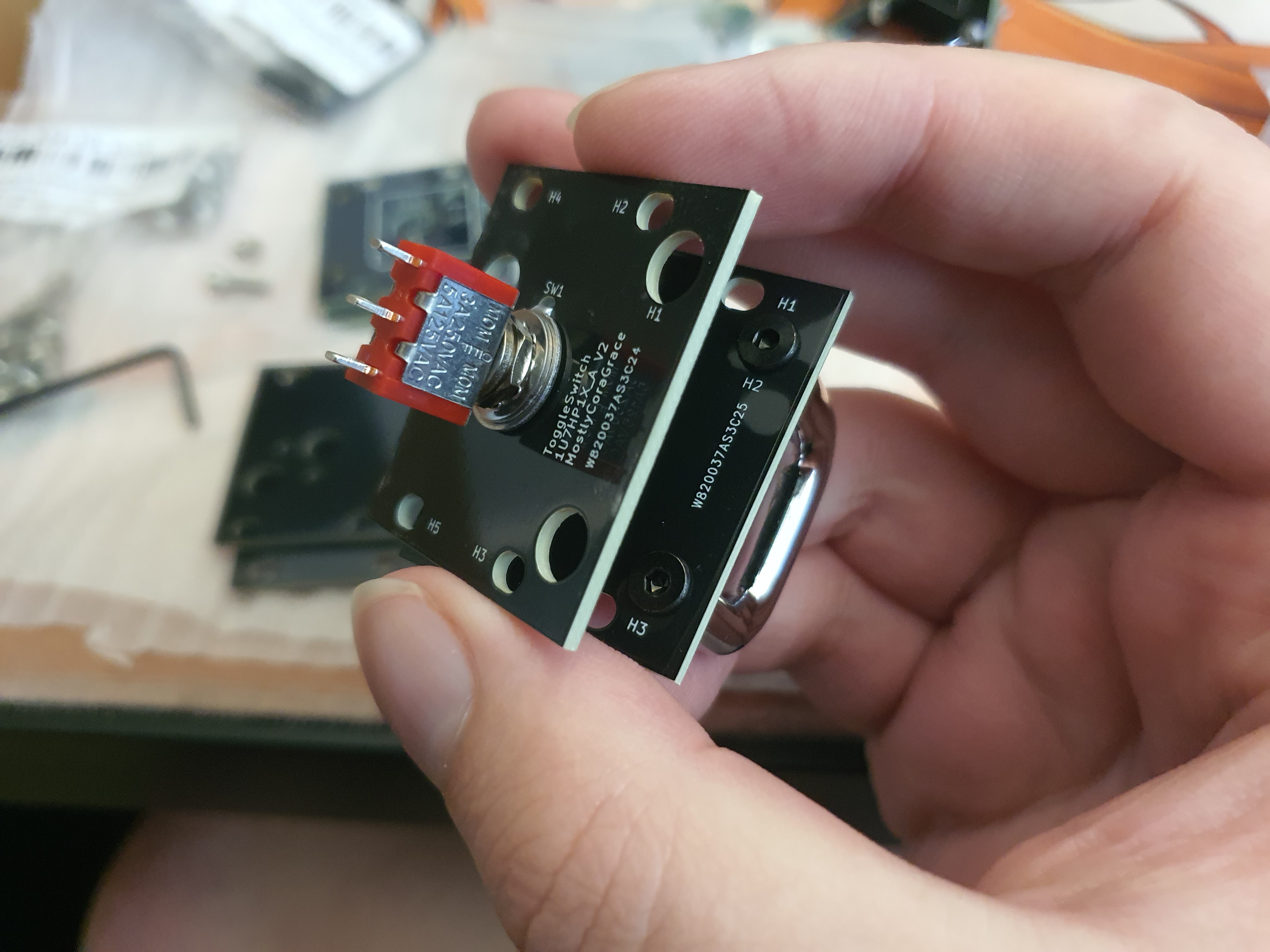
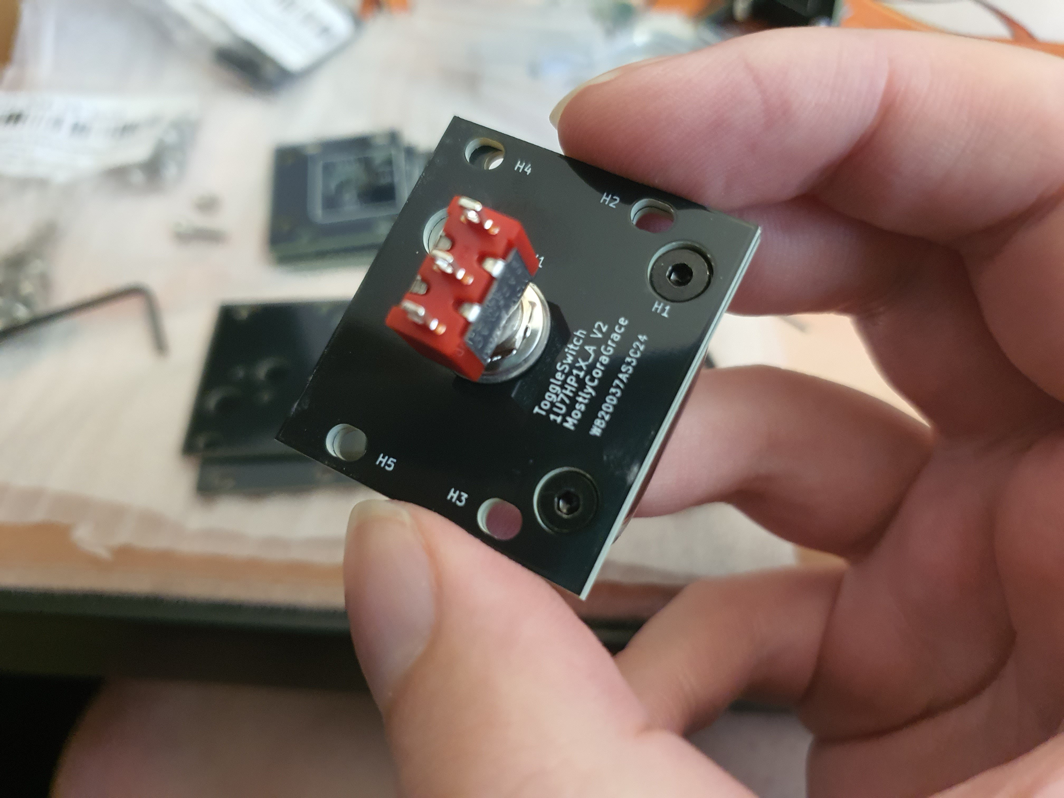
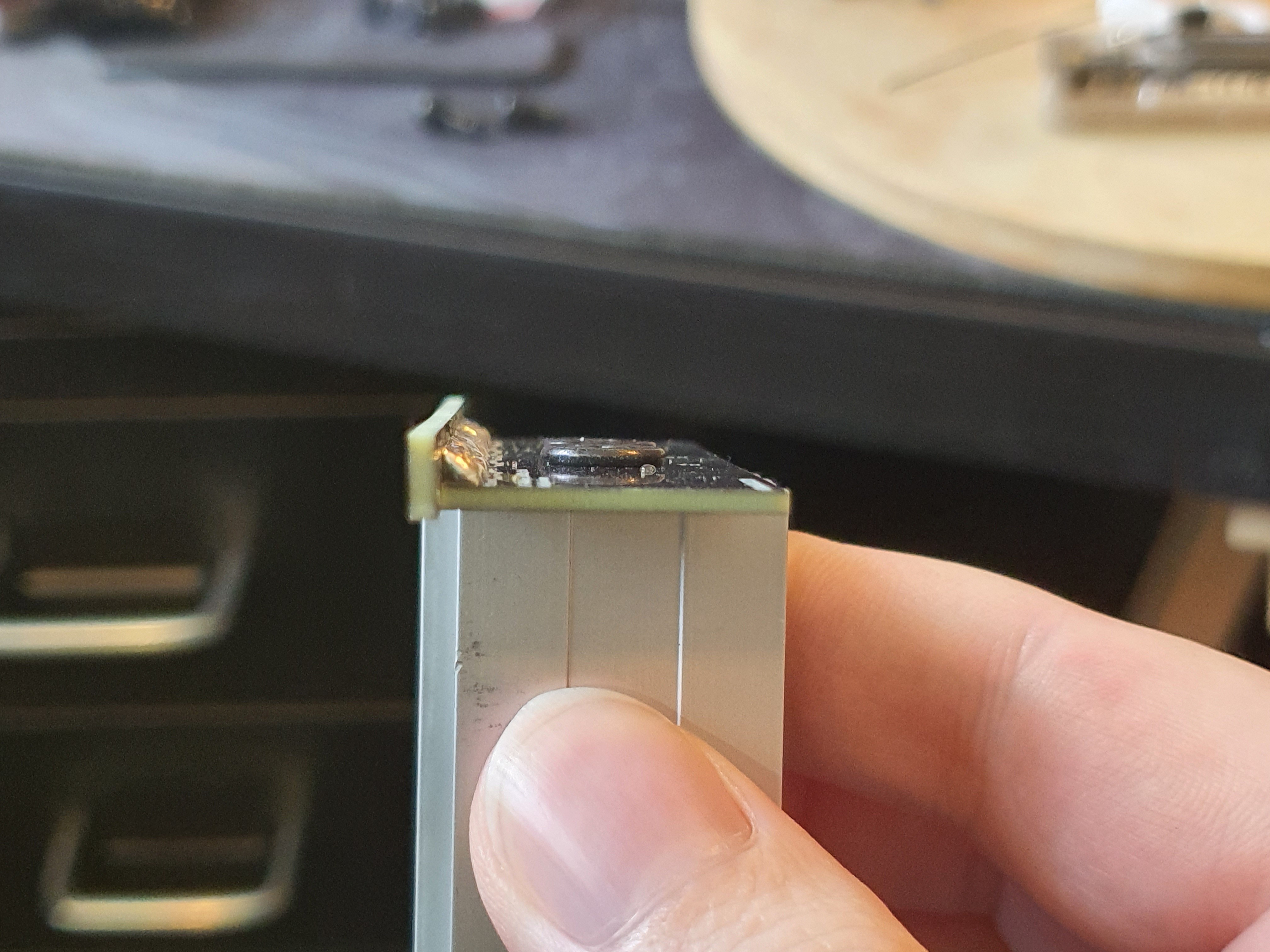
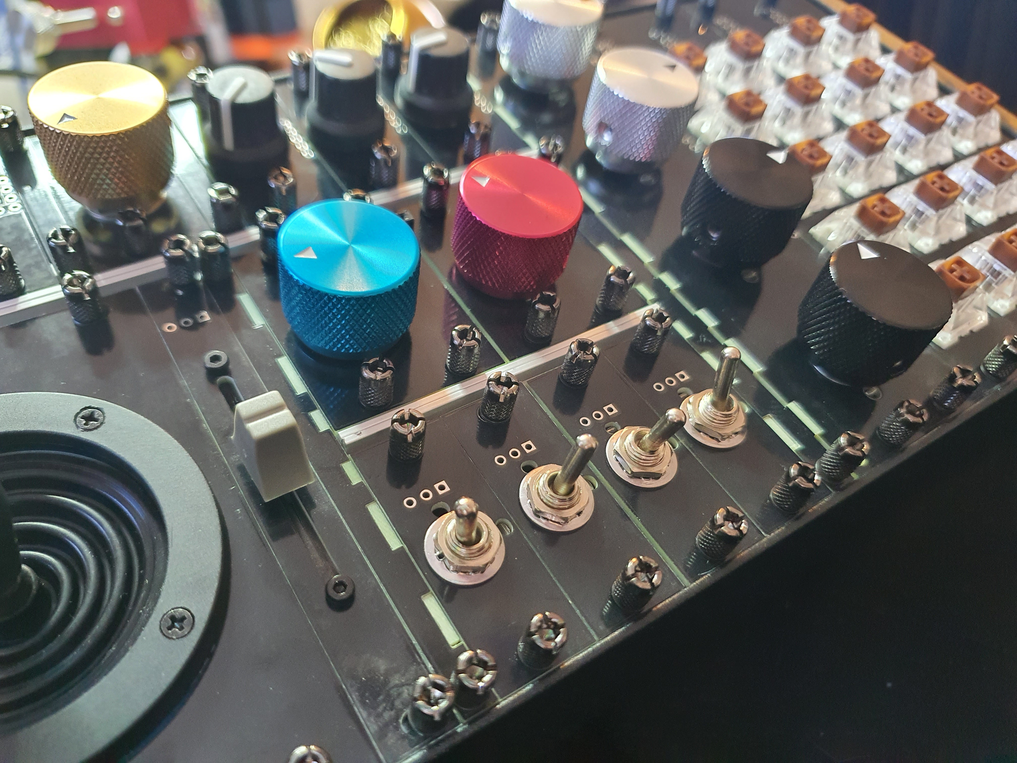
Since I was going for more of a military look, I also bought some more screws, this time going for flat hex M3 screws. Since I could only get three of them in there, you'll have to use your imagination a little bit, but here it is all assembled:
Attaching the handle was simple and just as effective as I thought it would be. Here is how it works:
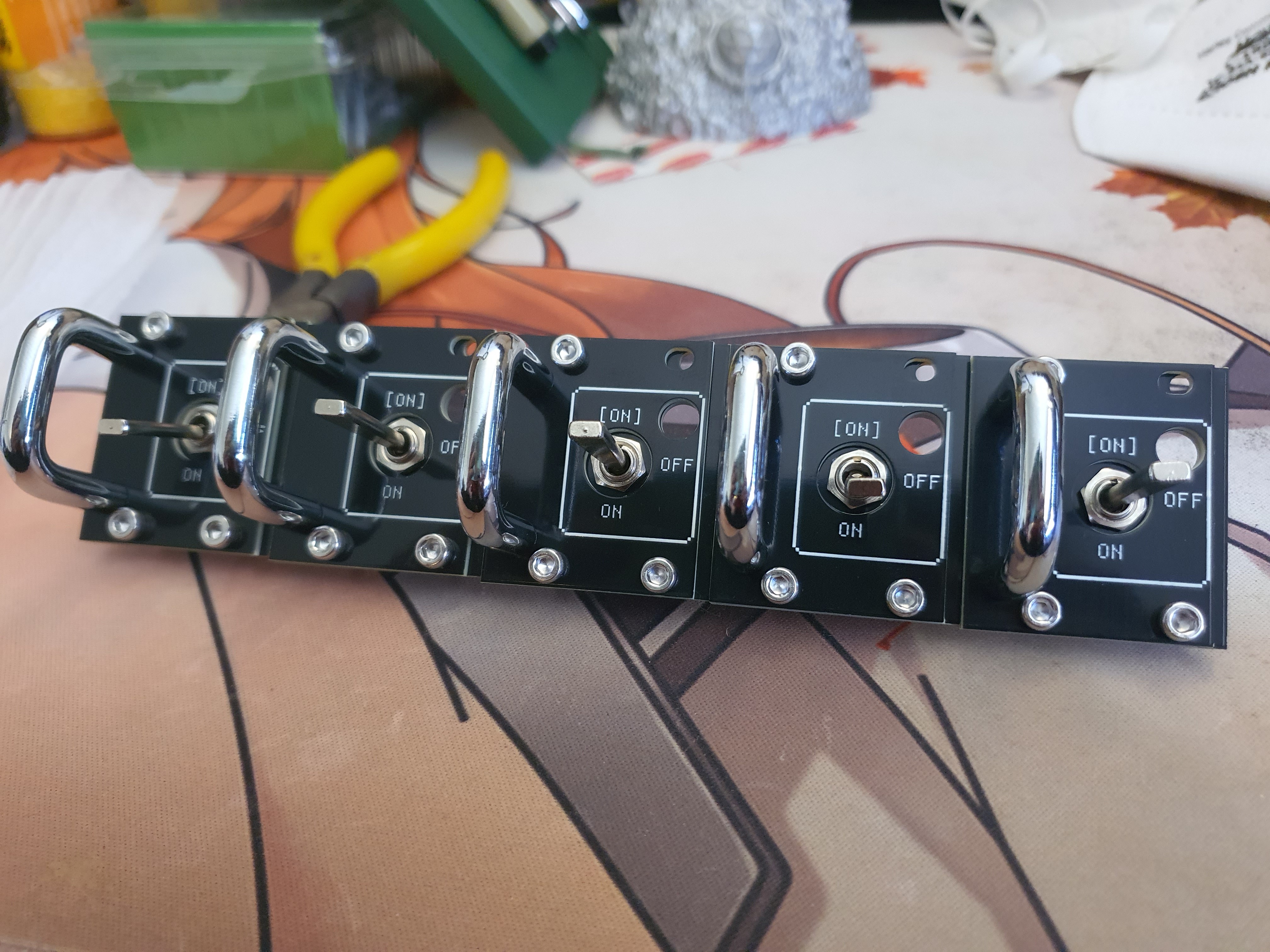
And here are several of them lined up, looking all fancy and chunky and ooh don't you just want to flick them!
They feel very chunky, and surprisingly sturdy. Who would've thought two layers of fibreglass would be strong! (sarcasm)
One interesting thing to note here is the switches are all ever-so-slightly mis-aligned...
Read more »Oh boy. This was a journey. Up until now, it had been smooth sailing; things I could do fairly quickly, nice neat updates I could make here and there, fun things to occupy my time. It was not to last.
Now, I'm not electrical engineer; I've not so much as even replaced a mains breaker. I'm barely literate. I dropped out of High School, I can't remember things well, and often repeat myself.
My previous soldering experience includes one keyboard I made from a kit I bought, and one other PCB project many years ago.
This project was ambitious.
It was A Time.
I had fun, yes, but it had its ups and downs. This update will attempt to highlight some of those ups, and some of those downs.
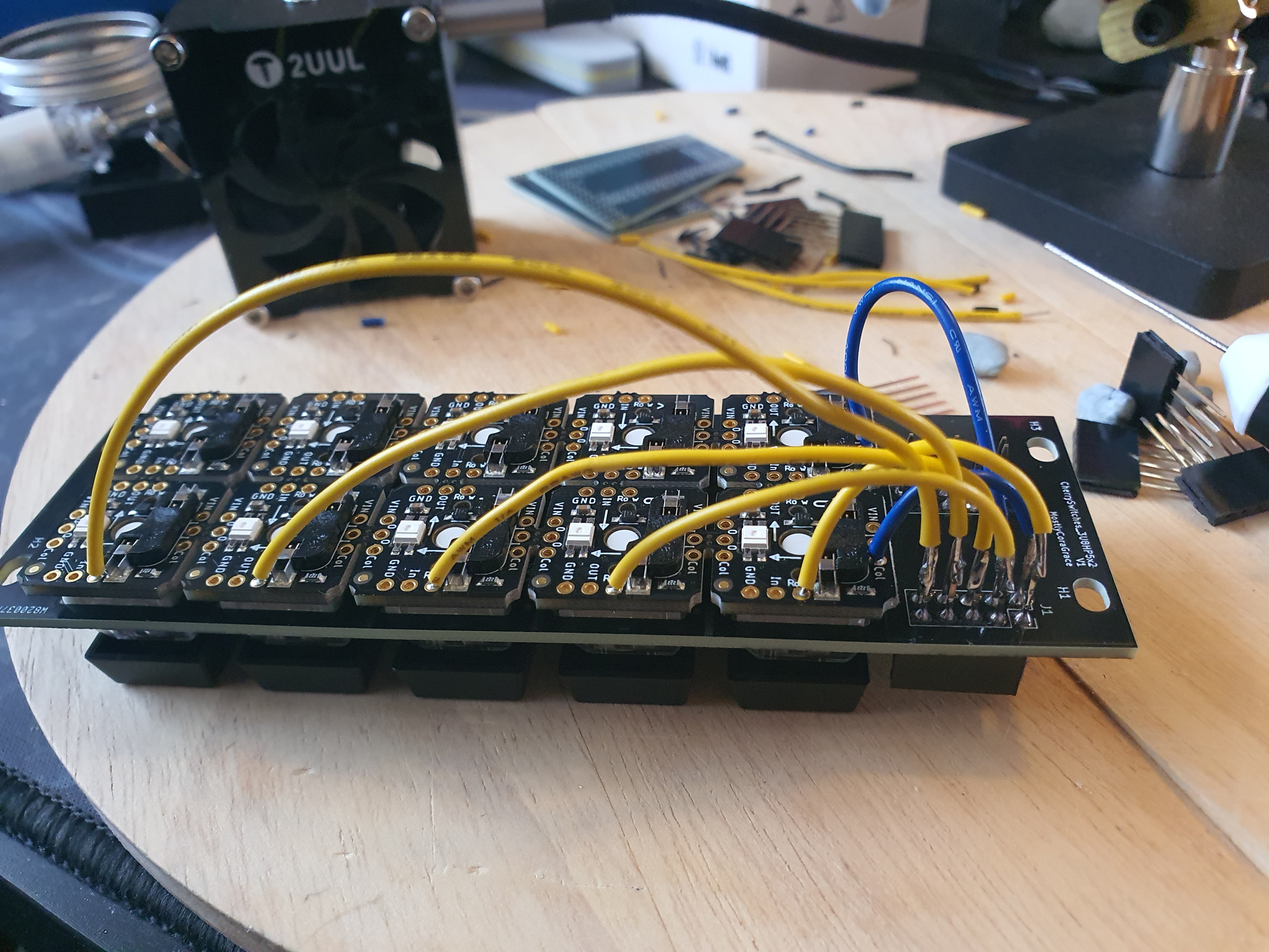
Soldering the first component to the first plate was a big high; cutting the wires to length, trimming the leads, soldering it on. But it was tedious, and I wasn't even sure if I wanted to keep all the wires on top. What if I got to the end, and decided that actually I wanted all the wiring underneath, inside the case? That would be prettier, it would match the aesthetic of a proper buttonboard better, and it would be less prone to breakage. So after finishing this, I decided to change my mind;
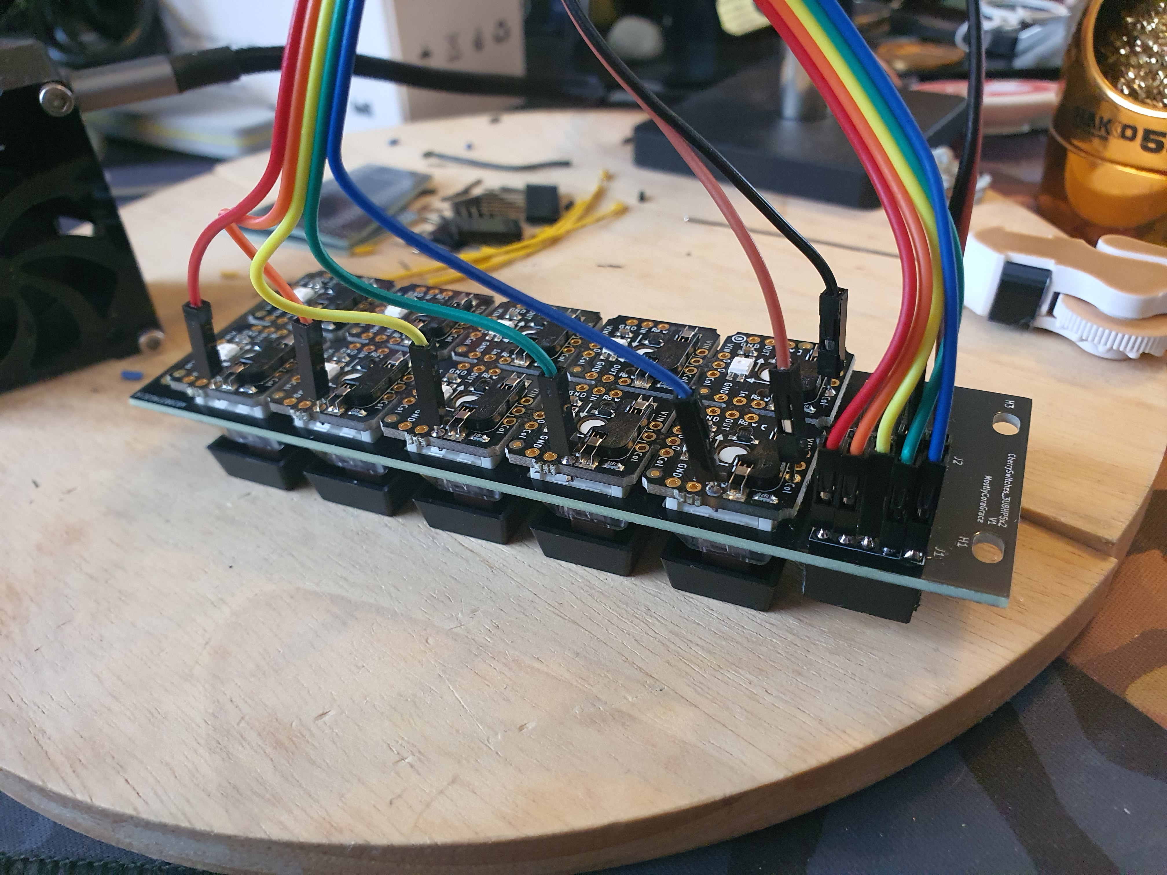
Thankfully, my brain is often bigger than I am. The headers I chose to use for the plates were the longer "Stacking Headers" AdaFruit have; they have a much longer male end, made for attaching several sets of headers together with PCBs between them. This meant I could use header leads on the undersides; solder one end to the component, and use the female end of the header to stick into the plate's header. This meant I could access them from the top, and also that I could unwire them without needing to de-solder them, if I ever decided to keep all the wires inside.
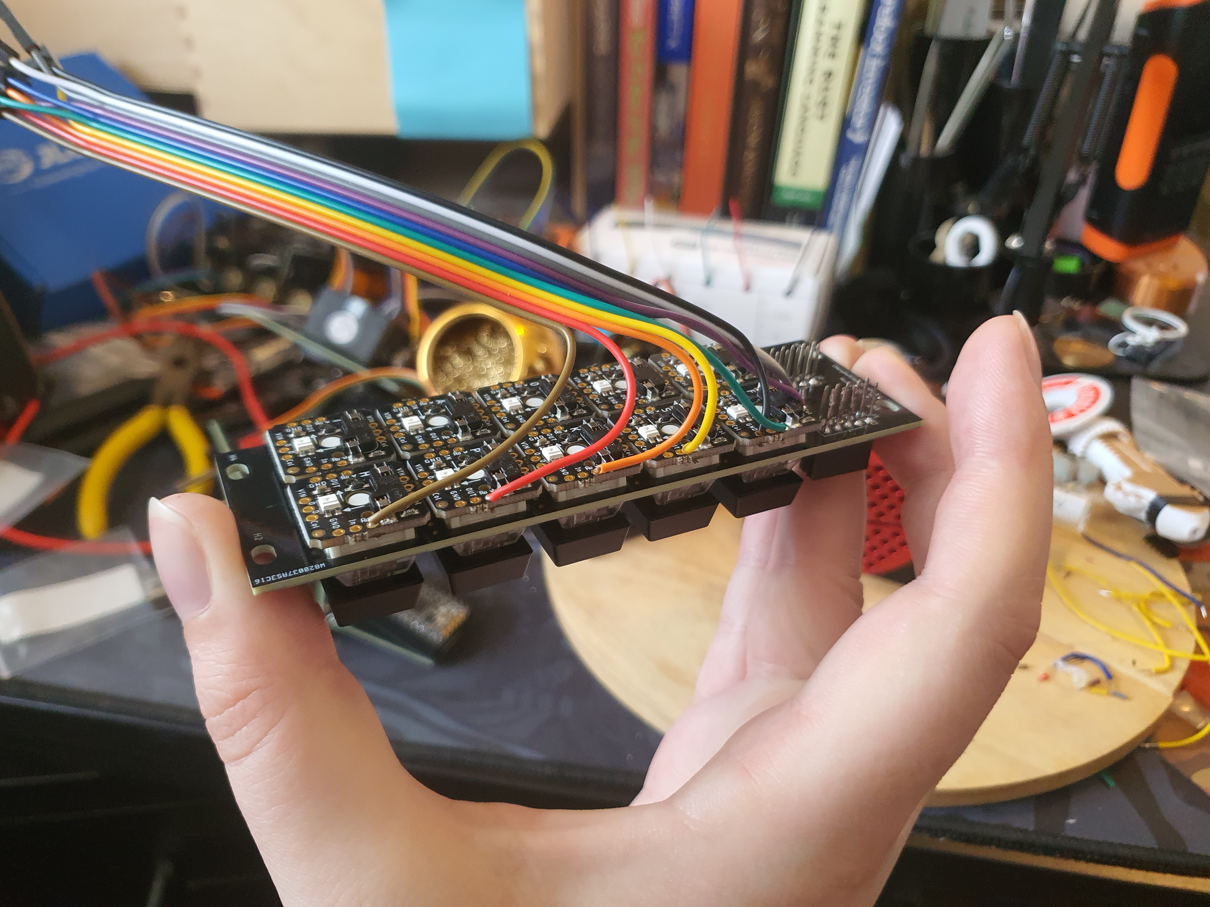
Repeating the process for the rest of the components, using one stripped end of the headers this time instead of soldering directly to the dupont leads like a dumbass, I managed to make some solid progress.
This took a few days! Maybe even a week or two.
I honestly don't remember. I'm writing all these updates in retrospect, since I have ADHD and have no concept of doing things properly. Everything must be done in a rush at the last possible moment, or not at all.
It took a while, regardless. My hands hurt. The tips of my fingers tingled. I googled lead poisoning and its effects comparing leaded solder with non-leaded to make sure I was washing my hands often enough, and ignored the "tingling extremities are a sign of acute lead poisoning" articles, since I knew, logically, that I was just sore from physical activity. I ordered some latex gloves online.
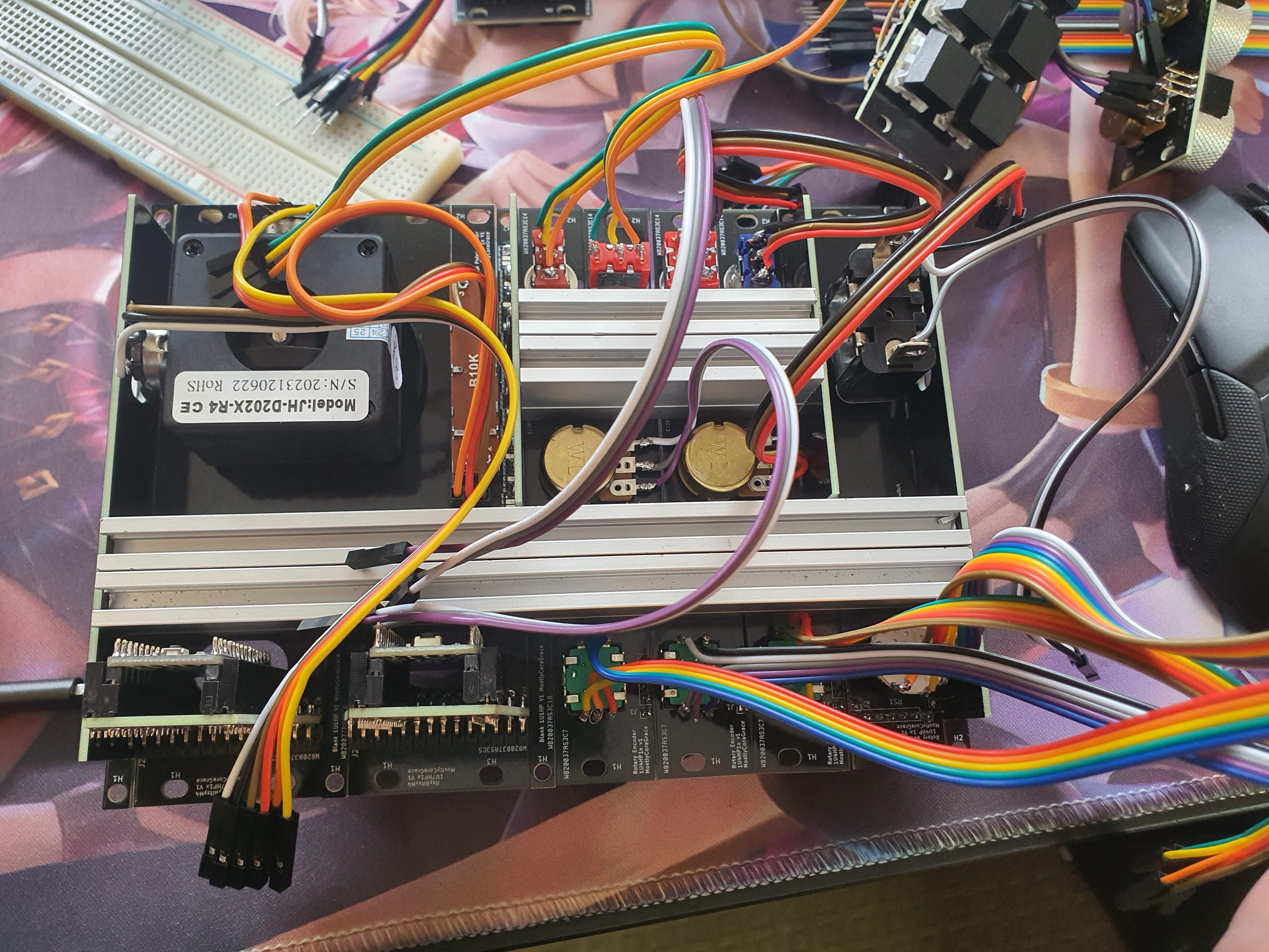
So I wanted to test that everything worked before screwing it all together. That's okay; I made all the leads removable for each component, so I can just connect a breadboard to each component via the wires already soldered to them! I'm thinking farther ahead than even I knew. Except now I need to wire the controllers too, and actually while I'm at it why don't I try and fit all the wiring in the case? There's plenty of space in there, surely I can fit the breadboard and the extra-long wires all in there! Lets give it a go.
Except I didn't consider the height of the dupont wires when I designed the 1U plates for the controllers:
No matter, I can solder male headers directly to the wires, at a right-angle, and make my own dupont wires! I'm a genius!
Yeah, that works just fine.
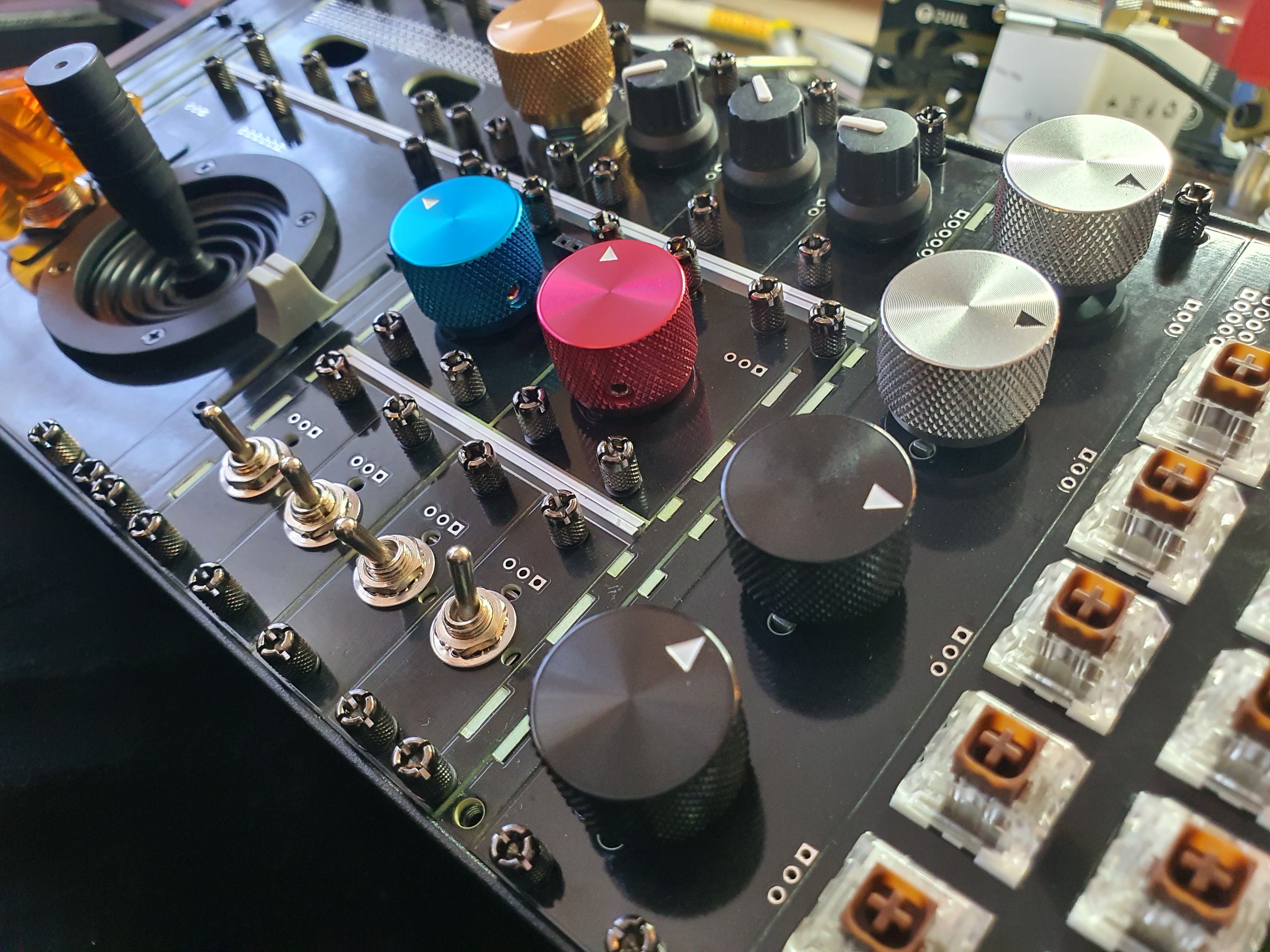
Connecting all the extra wiring together, on a breadboard, was easy enough. It's a *lot* of wires though! so much spaghetti. It did remind me of one thing I had overlooked, which is that many of the components need to be routed to 3.3V or Ground, and if I were to wire this up on the top, I would have no place to wire them up; I hadn't ordered any of the perfboard plates I designed, and I hadn't designed any power or ground buses into the controller board or plates,...
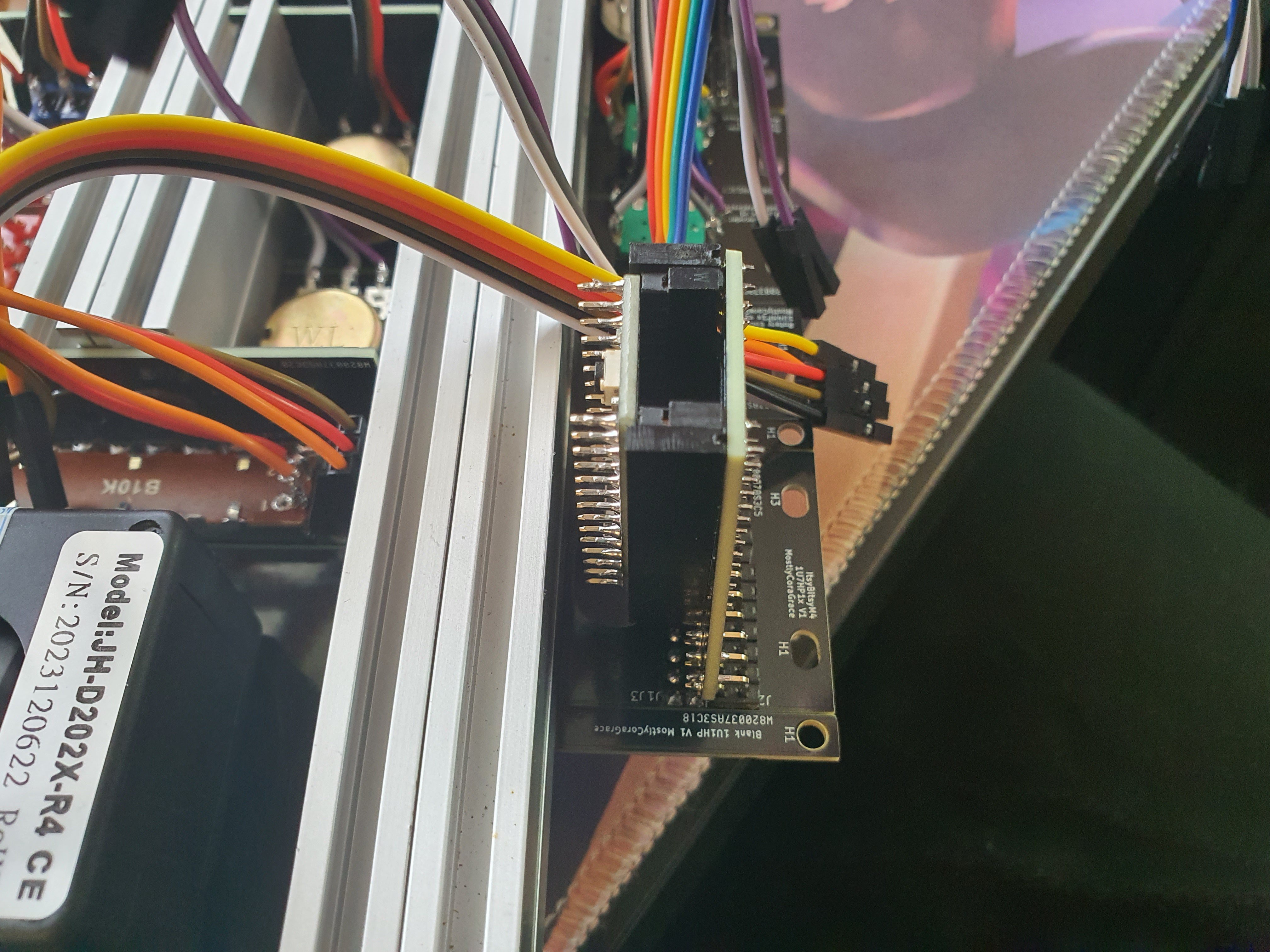
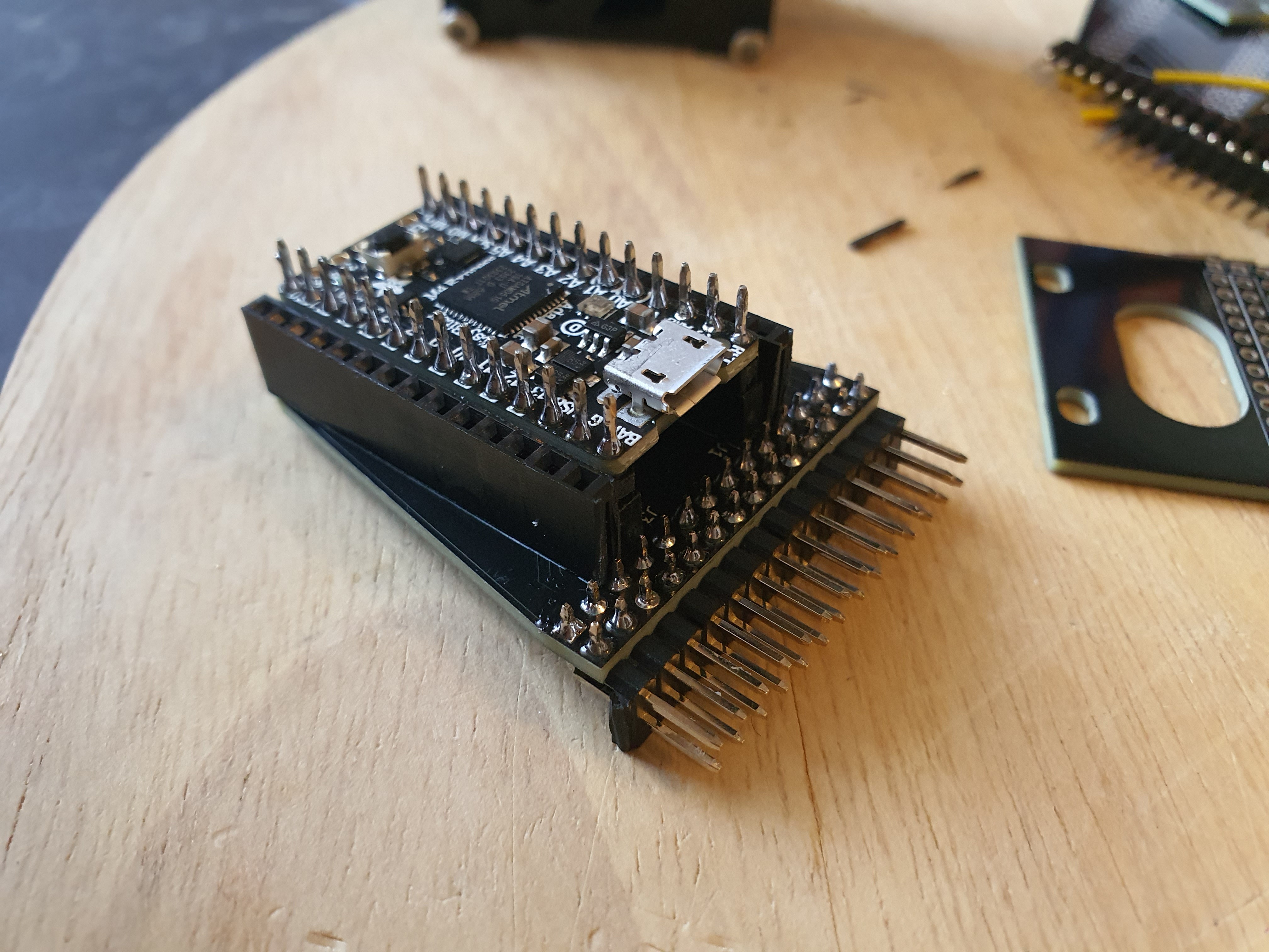
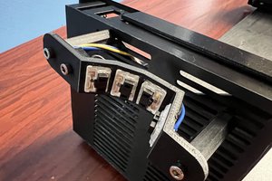
Read more »When designing the components, I wanted the USB controller to be a part of the design, instead of just hidden inside the case.
Part of the aesthetic of this project is to mirror the beauty of the Eurorack scene by making the chaotic wiring a part of the design, and that means the headers of the controller need to be just as exposed as the components I'm connecting to them. Since I also wanted to make sure none of the exposed sections of the design had anything poisonous on them, that meant I couldn't simply have the controllers connected flat on the plate with some headers. I briefly experimented with this, but they took up a comparatively large area, meant the attachment points would have to be underneath the controller, and meant I couldn't just have them side-by-side (since the USB connector would interfere with whatever was next to them). So a more... *complicated* solution was required.
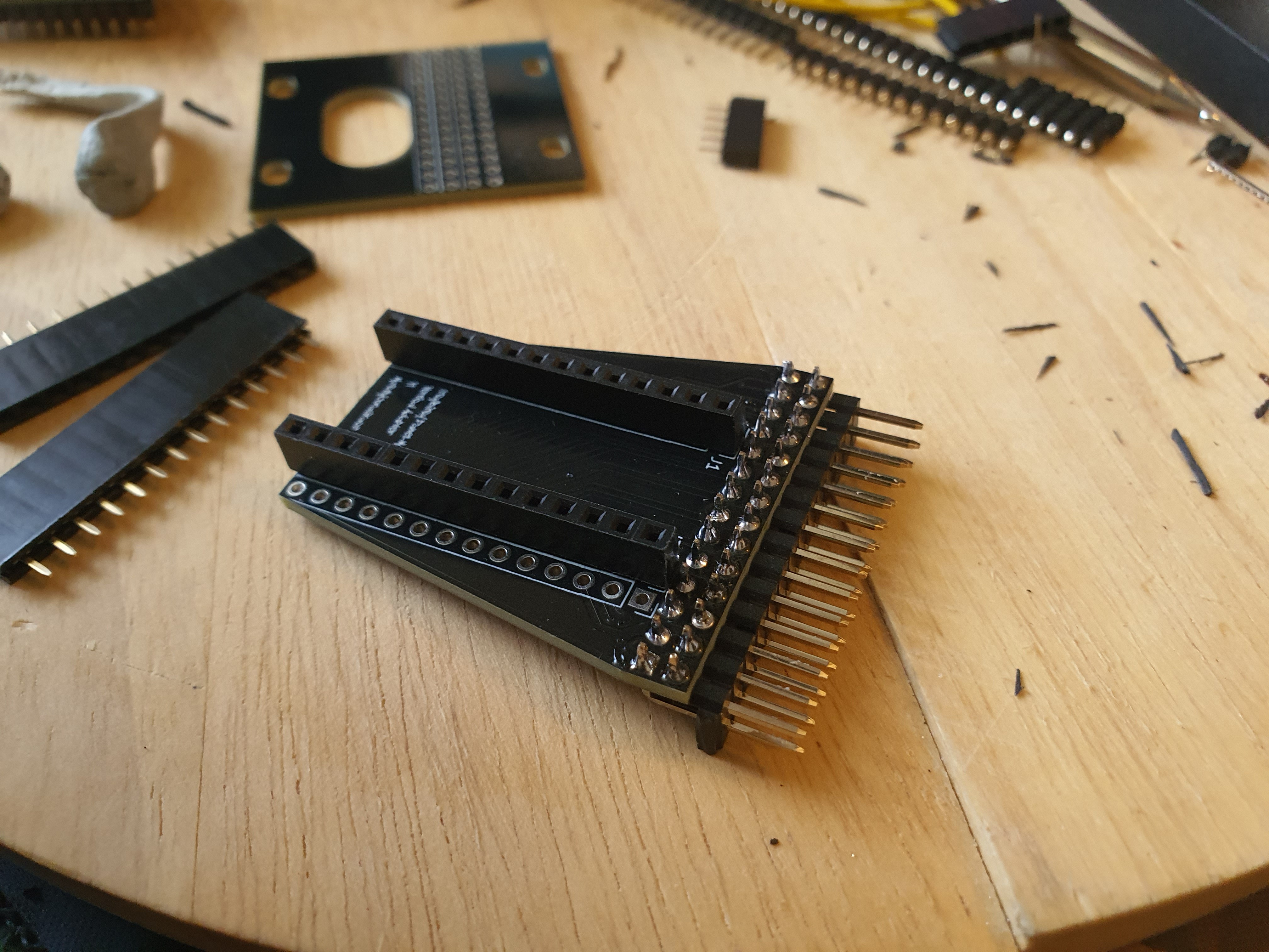
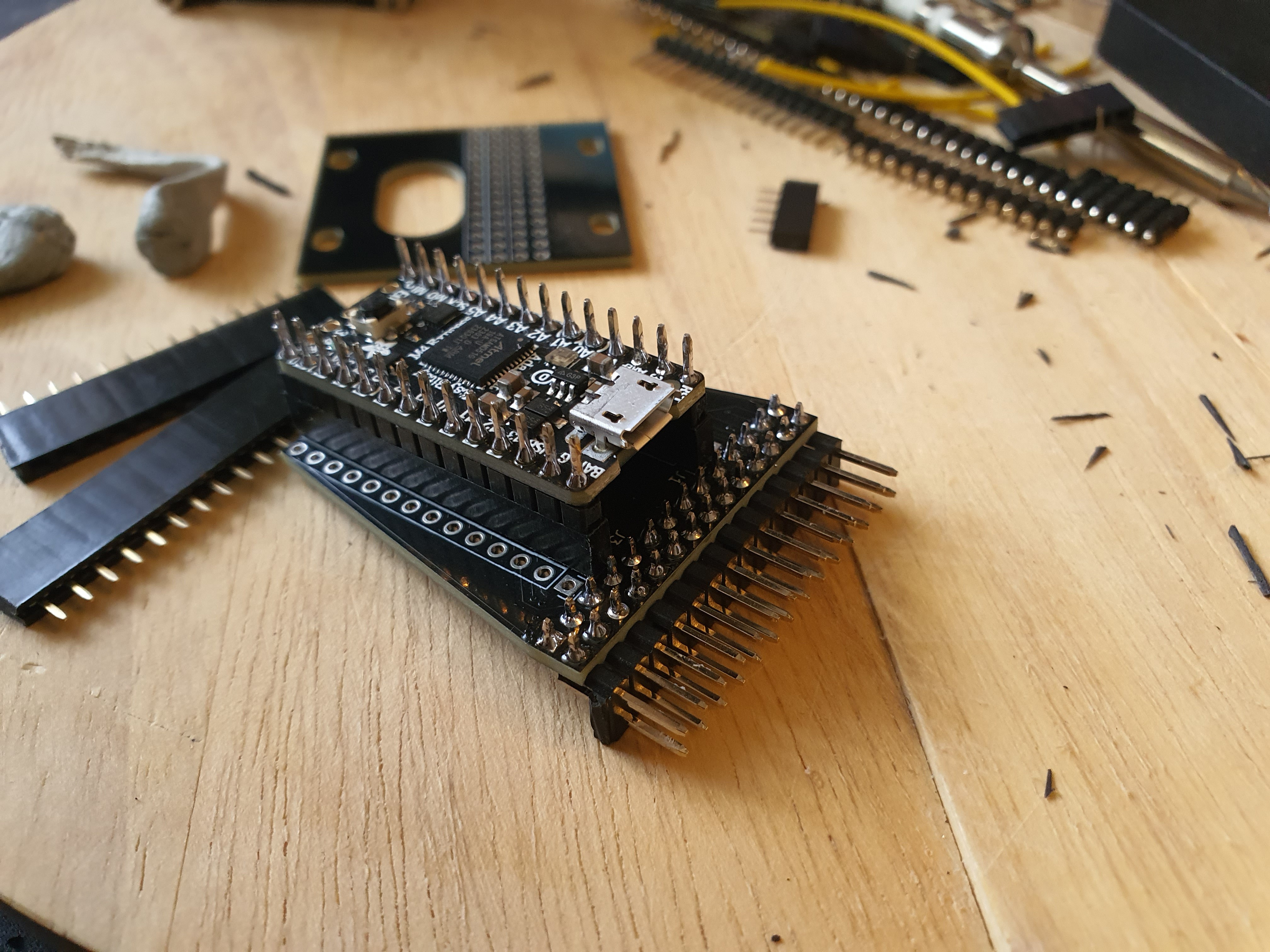
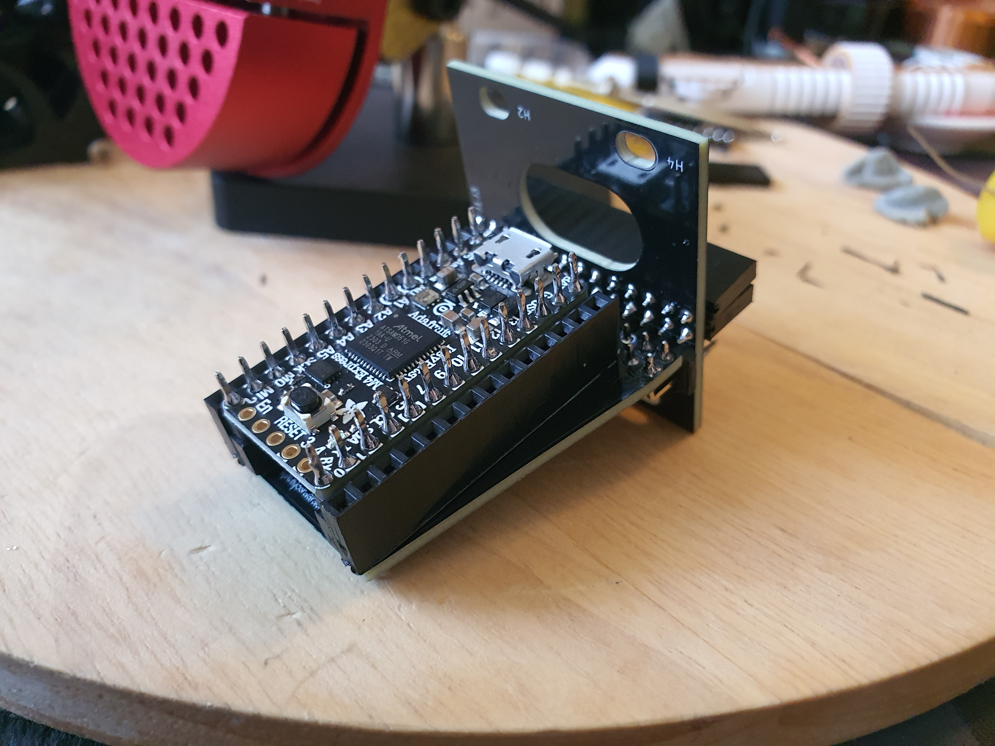
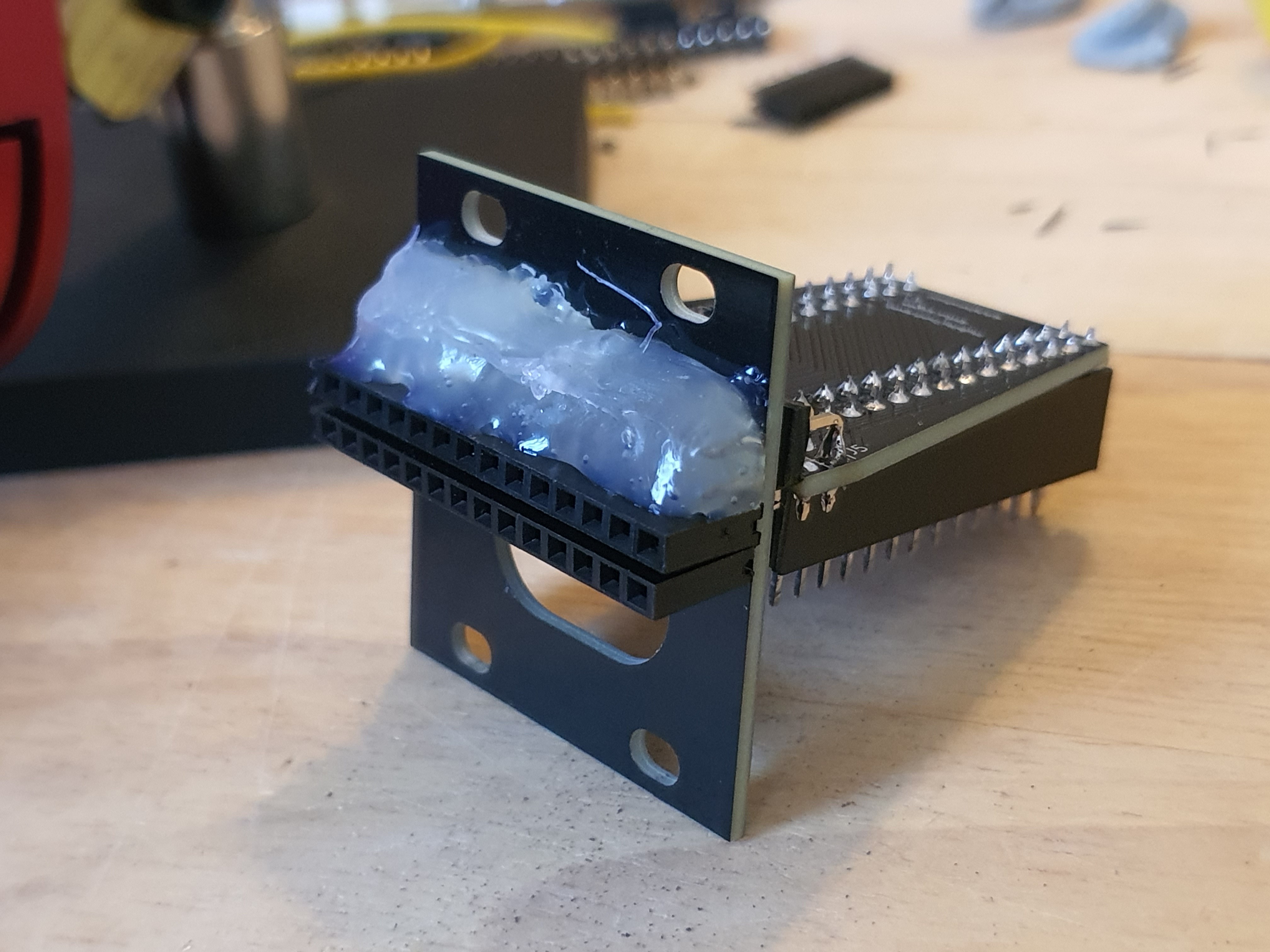
If I used right-angle header connectors as a physical connection as well as an electronic one, I could mount the controller vertically *inside* the case, with the USB port pointing out the same as all the headers, and it would take up much less space! So this is what I went ahead with. Now with the parts in front of me, I wasn't sure quite where to start; the fugue state I designed them in long past, figuring out the correct assembly order such that none of the parts became inaccessible to soon proved challenging.
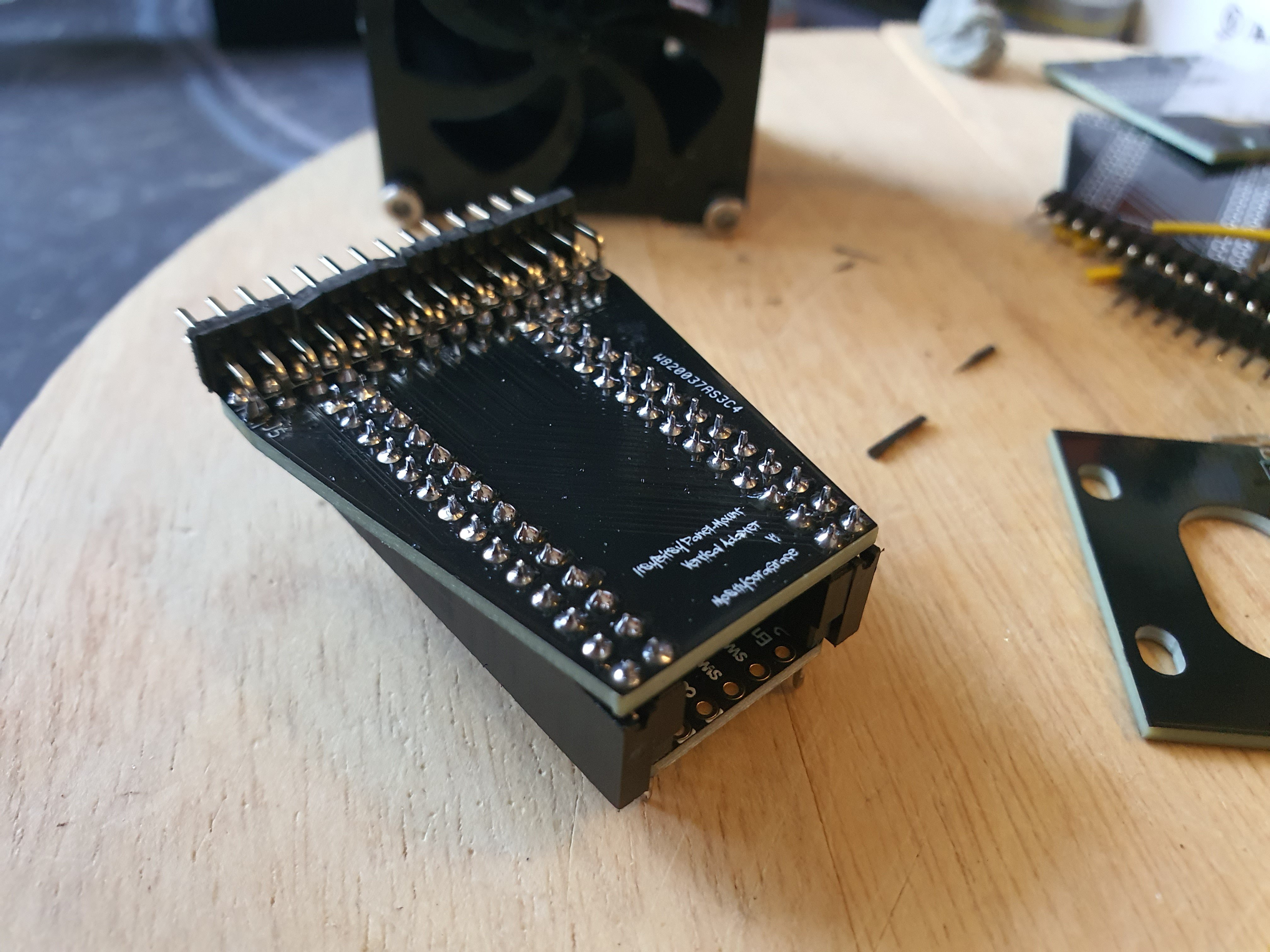
I managed to get the two sets of female headers, and one half of the right-angle headers, soldered on, and the other female headers and the other half of the right-angle headers soldered on, so all's well that ends well! It sure was a lot of soldering! Gee I sure hope it all works out...
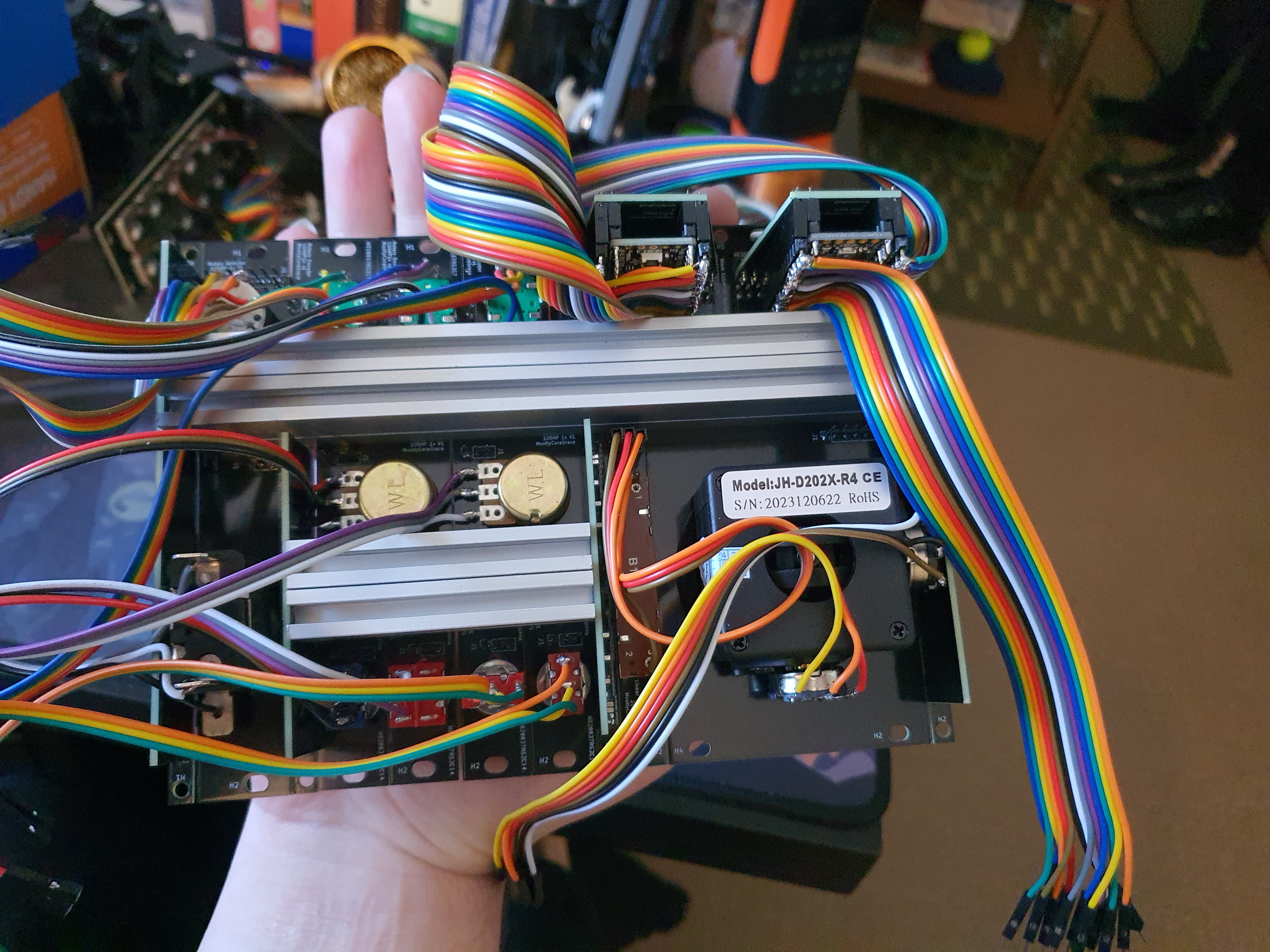
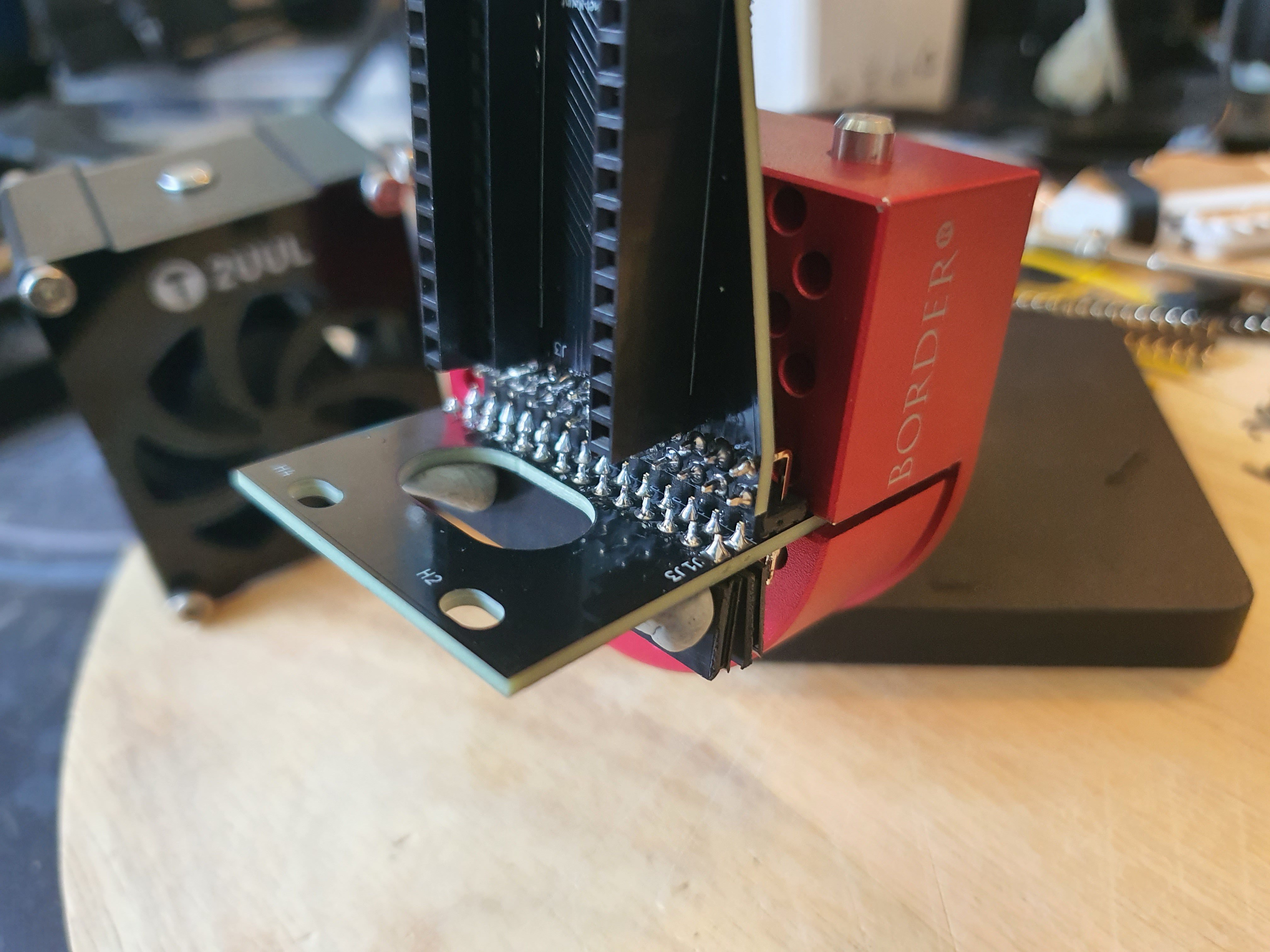
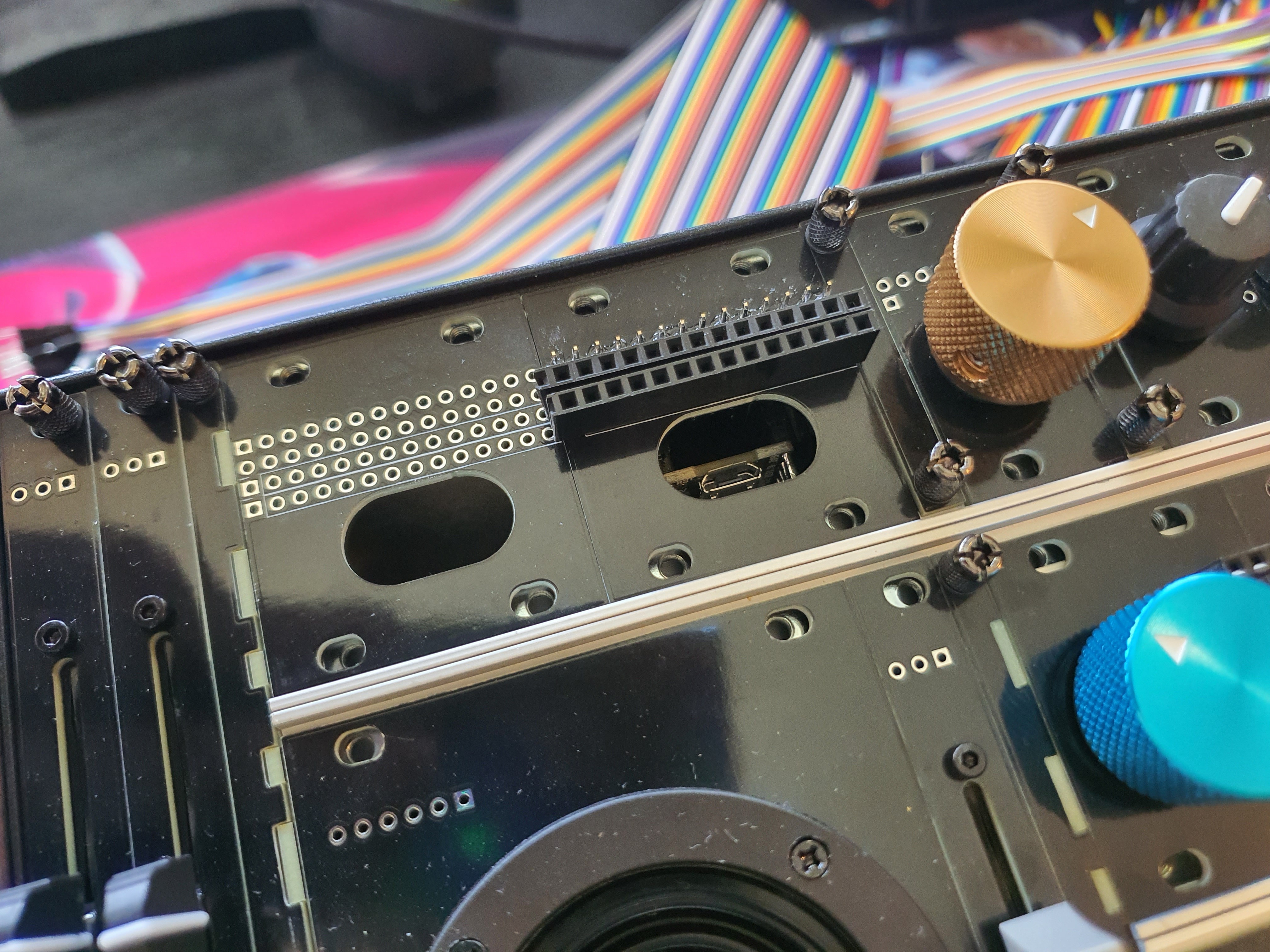
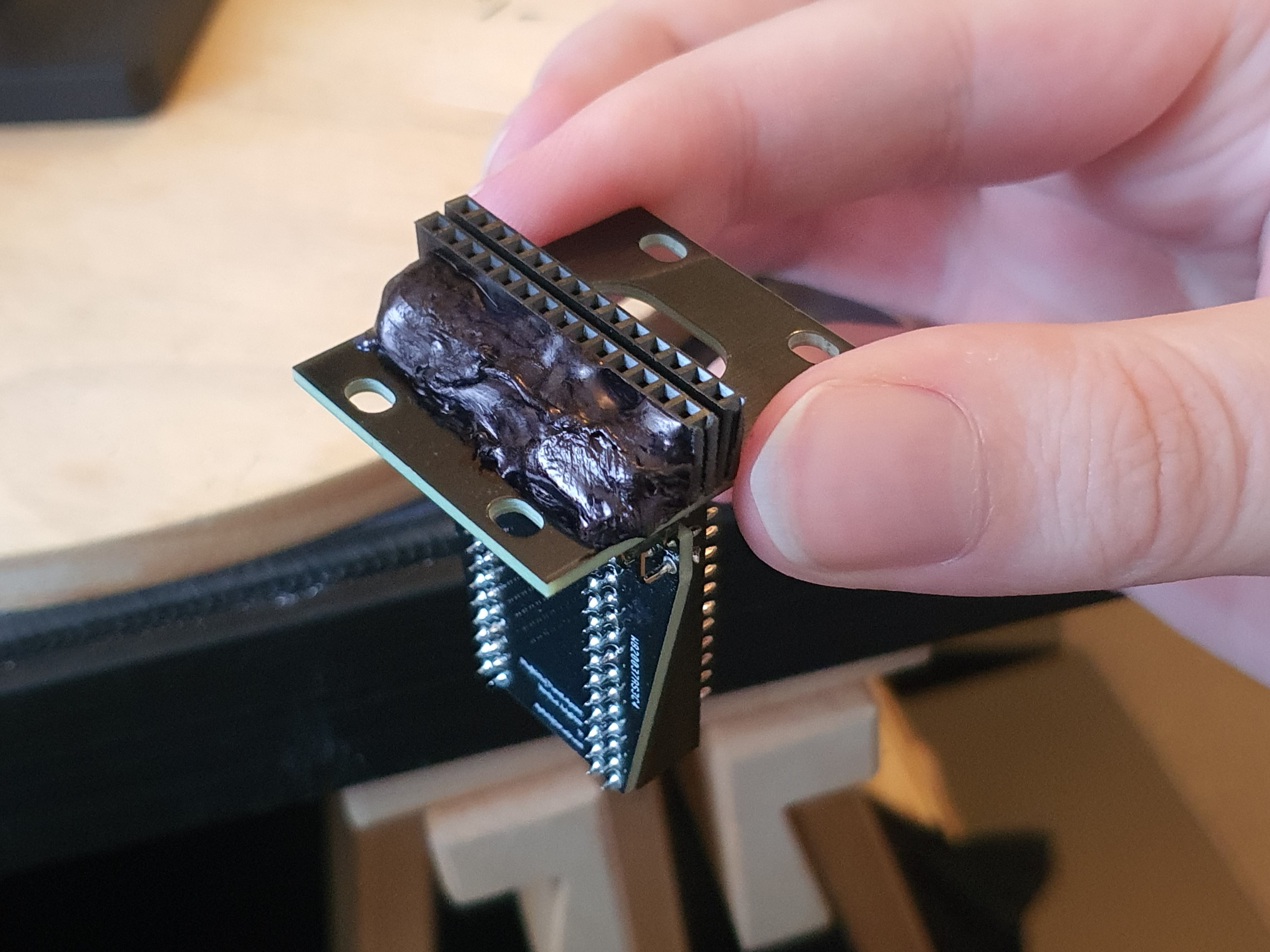
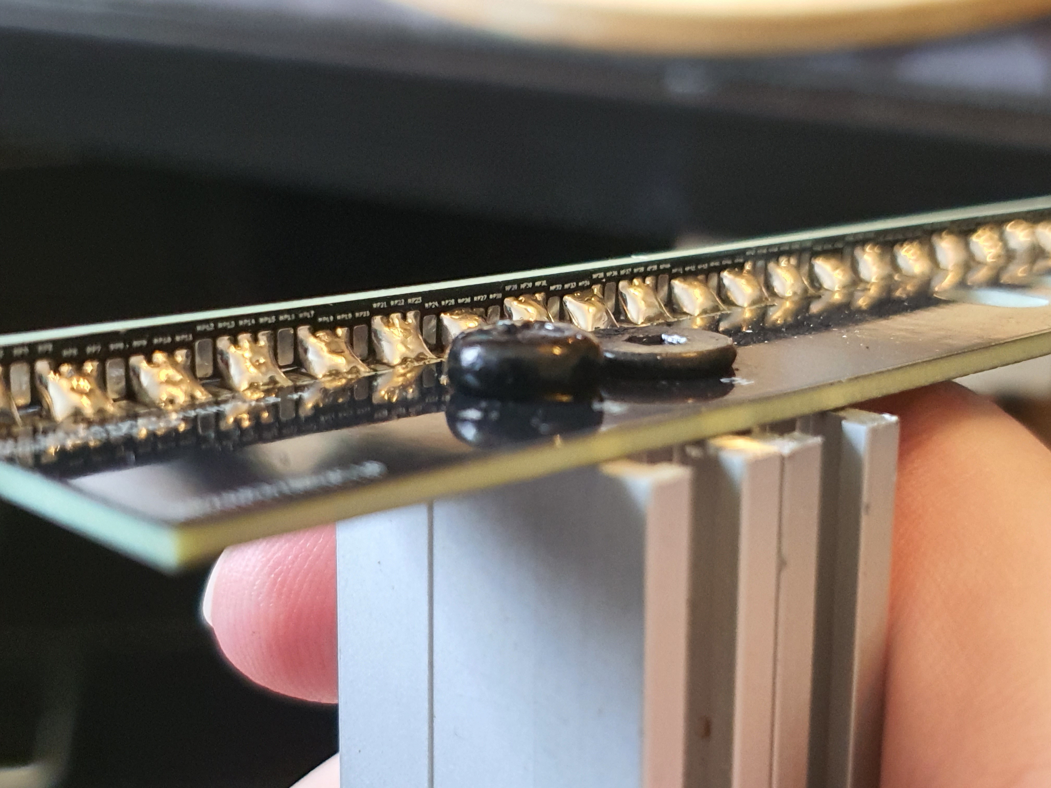
Once I had them assembled, I realized an error! A mistake! A design aspect I had neglected to consider! The headers overlapping the plate next to it I can work around, this part of the design has several blank plates on it for a reason, but the headers are exposed!
It wasn't that big of a deal, but now that it was in my hands, I could see that the top section of the right-angled headers poked out of the plate, and would expose the toxic leaded solder to my beautiful fingies whenever I were to fiddle with this after its assembly! This I could not abide, and my quick fix was to just... throw some hot glue over them and draw on it with some sharpie to make it look not quite so bad lmao.
This will, thankfully, be hidden behind all the chaos of the wiring once it's all done and dusted, but until then it does look quite comical compared to the quality of everything else so far.
So the nice thin screws for the adapter plates came in the mail! It turns out the cheap ones I got from my local hardware store fit fine anyway, but the new ones are a lot nicer:
Anyway, that's all for now!
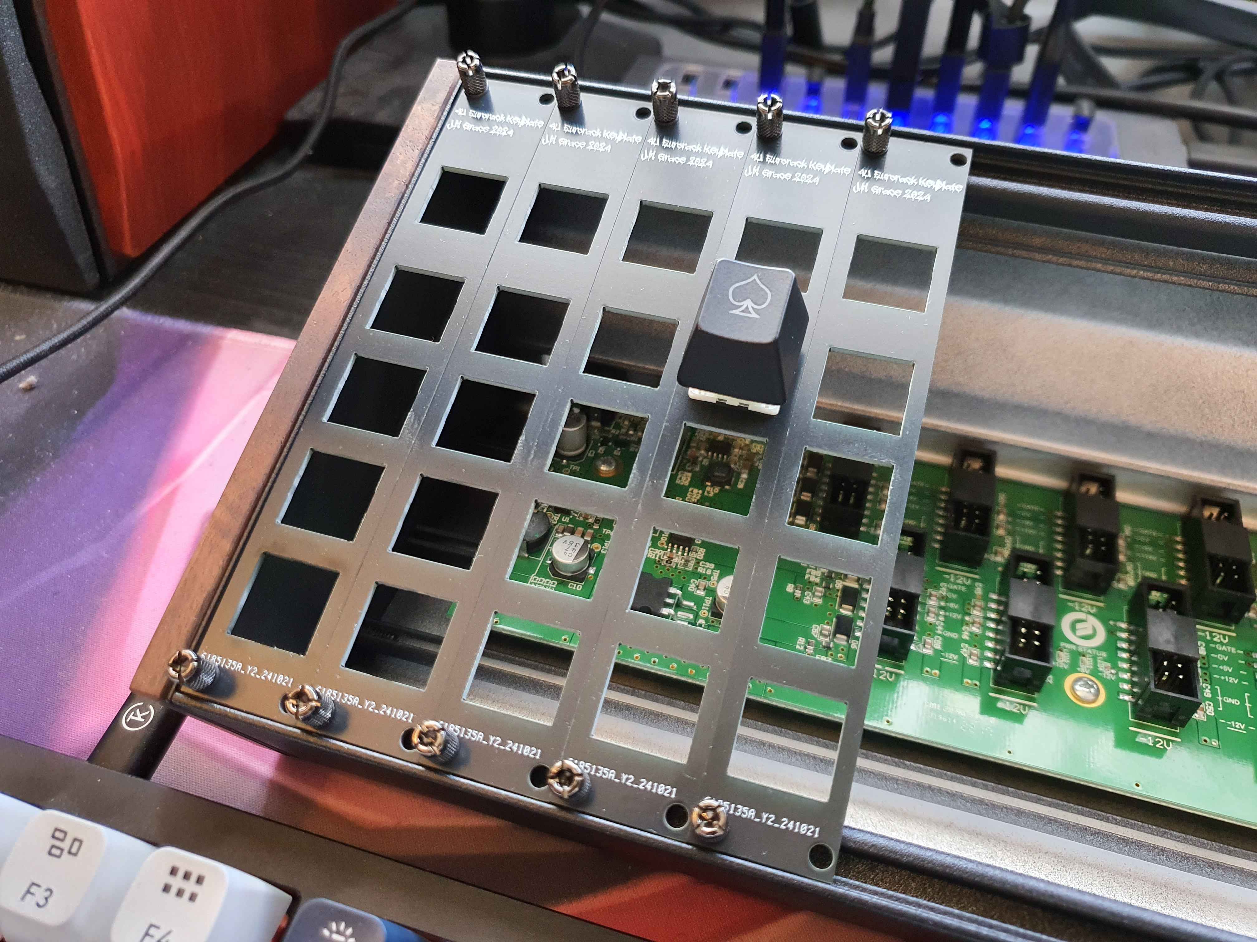
Once all the components spent their time in transit and were all collected on my workbench, I decided the first order of business was to dry-fit everything together; it wouldn't do if any of the parts I ordered were off or mis-sized, either by fault of my own design or otherwise!
First up, the plates:
so far so good!
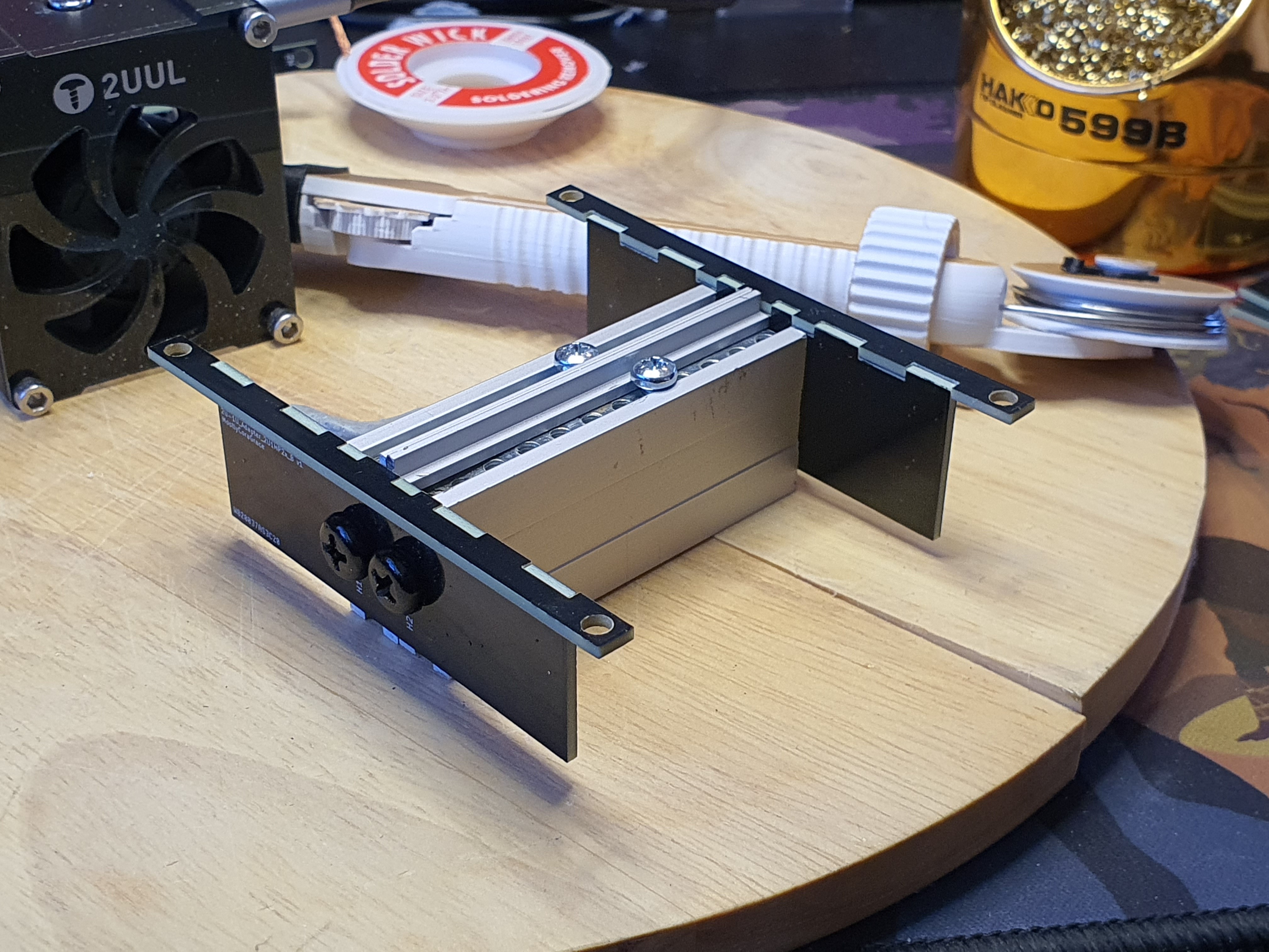
In order to dry-fit the more interesting 1U and 2U parts, I'm going to need to assemble the adapters I designed. The screws for them haven't arrived yet, but I ordered some other not-quite-as-nice ones from my local hardware store, and they will do for now.
I designed each of the parts such that they would be quite tight, but even so I did need to take a small file to them to get them to fully fit together. If I were to re-design them, I would add areas into the inner corners of each of the fingers to make sure the mill didn't leave too much material in between them. Thankfully, they didn't need much filing, and after a few attempts, they went together nicely.
Lining the two parts up with some blu-tac to hold it all together while I work, I first soldered just one corner on, then the other, and when I was happy with the angle I finished the middle sections.
PCBs have a bit of slack in them, and I took advantage of that as I worked the corners. I could finish one corner, check the angle of the plates, and bend the other corner into shape while the solder was hot, then simply re-heat the opposite corner to release the stress.
I designed many separate PCB-Attachment sections into the design because I wasn't sure if one single large slot would work, in terms of being able to heat it all up with my soldering iron while the solder melted into place, but I also kept in mind that the very tiny (1.25mm) slots might be too small to bother doing individually. I played around with a few combinations until I found one that worked nicely for me, which ended up being sets of 3 soldered together with one set between each. This was much easier to solder, and not too finicky to deal with.
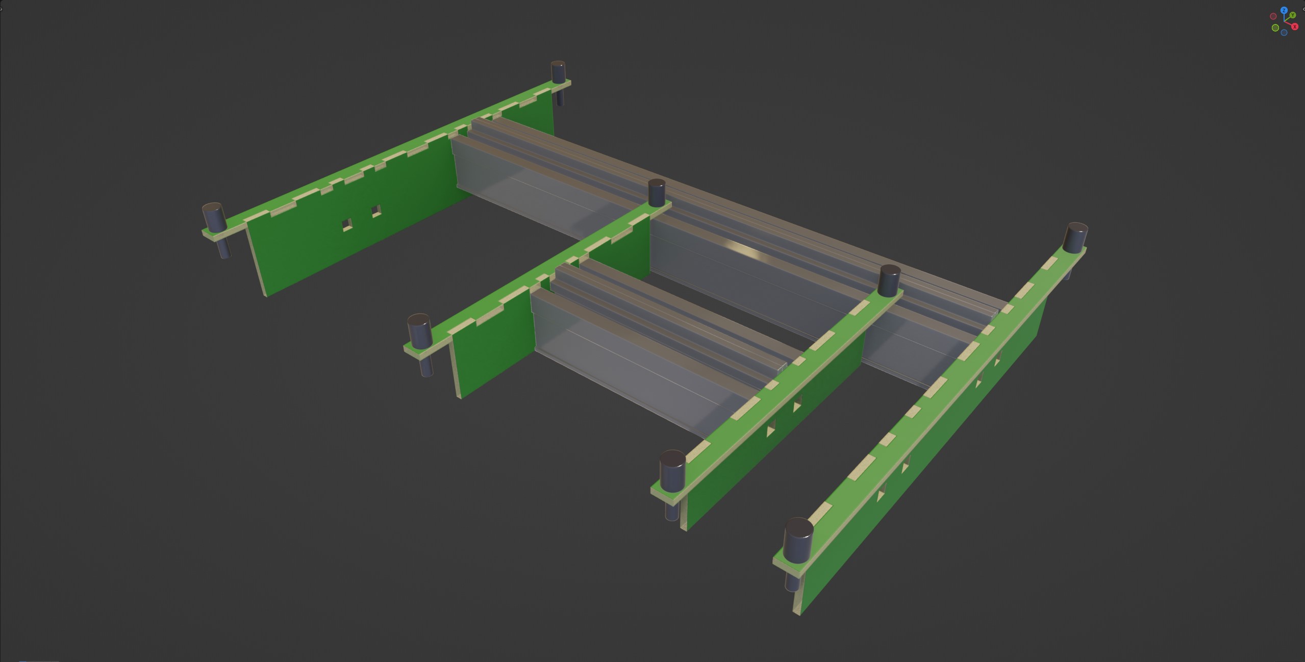
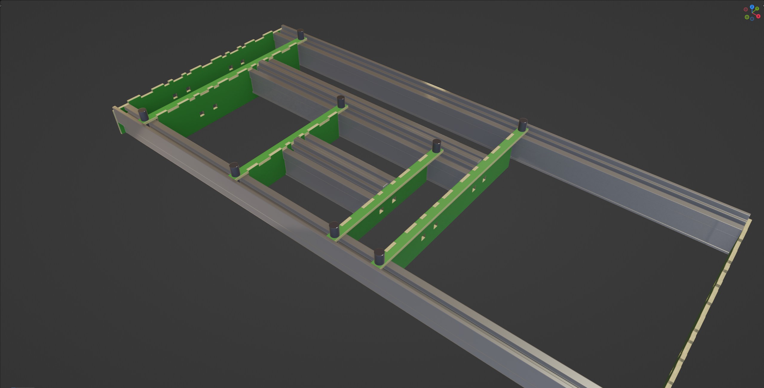
Lining them up on the table once they were done, I could get the screws tightened on the rails and make sure they were tried and true. The PCBs were nice and strong, and the rails light, so they didn't need much tightening, and all in all it was fairly painless!
I then put the rails into the case, and made sure they fit, and.. oh that's really quite nice, isn't it?
Maybe I will mention this in the Eurorack community, I'm sure someone would love a nice homemade alternative to some of the 3U-to-1U adapters, especially one as flexible as this! Just order the lengths you want, and solder it, and it's done! Perhaps I will do this alongside the publishing of this log update.
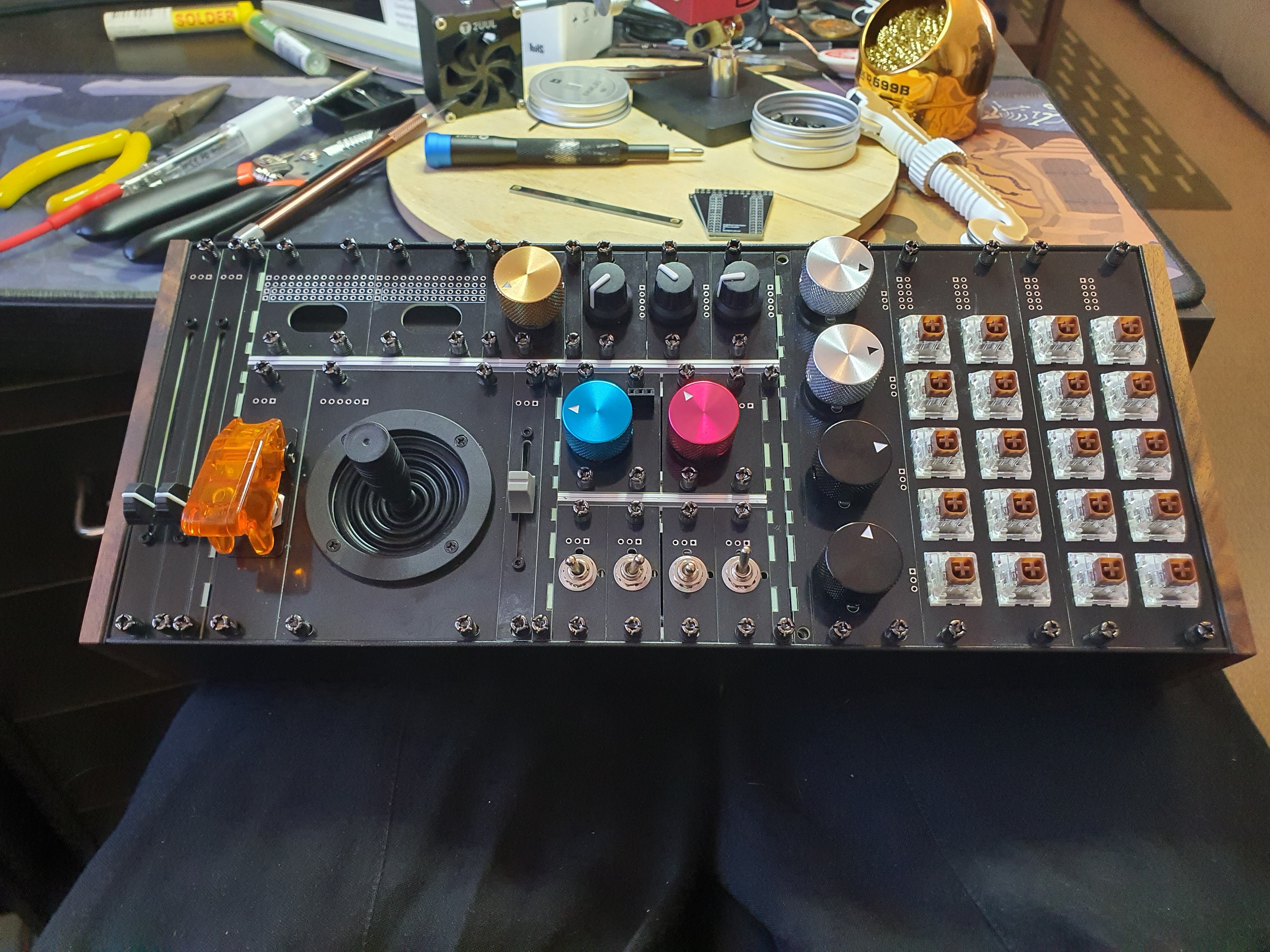
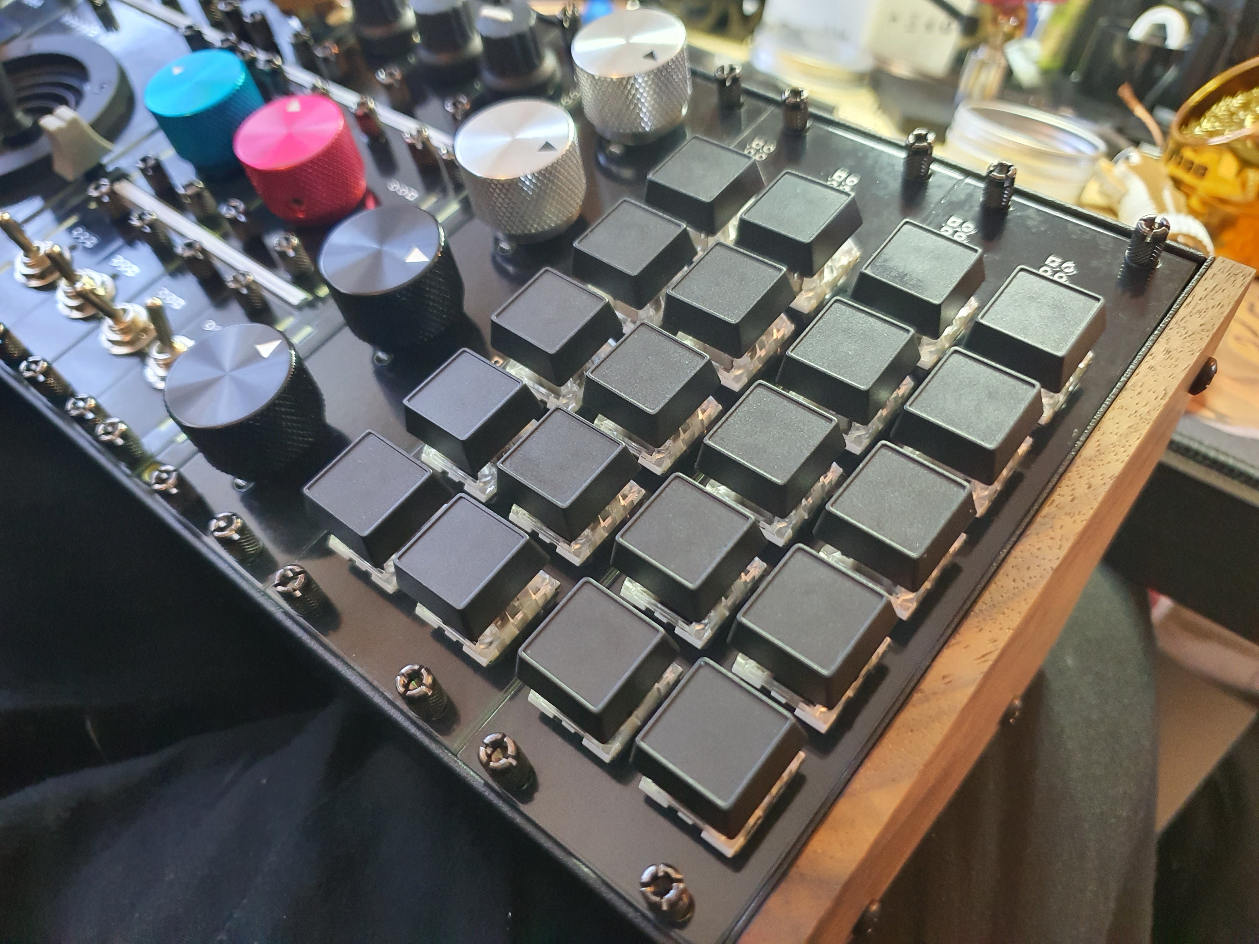
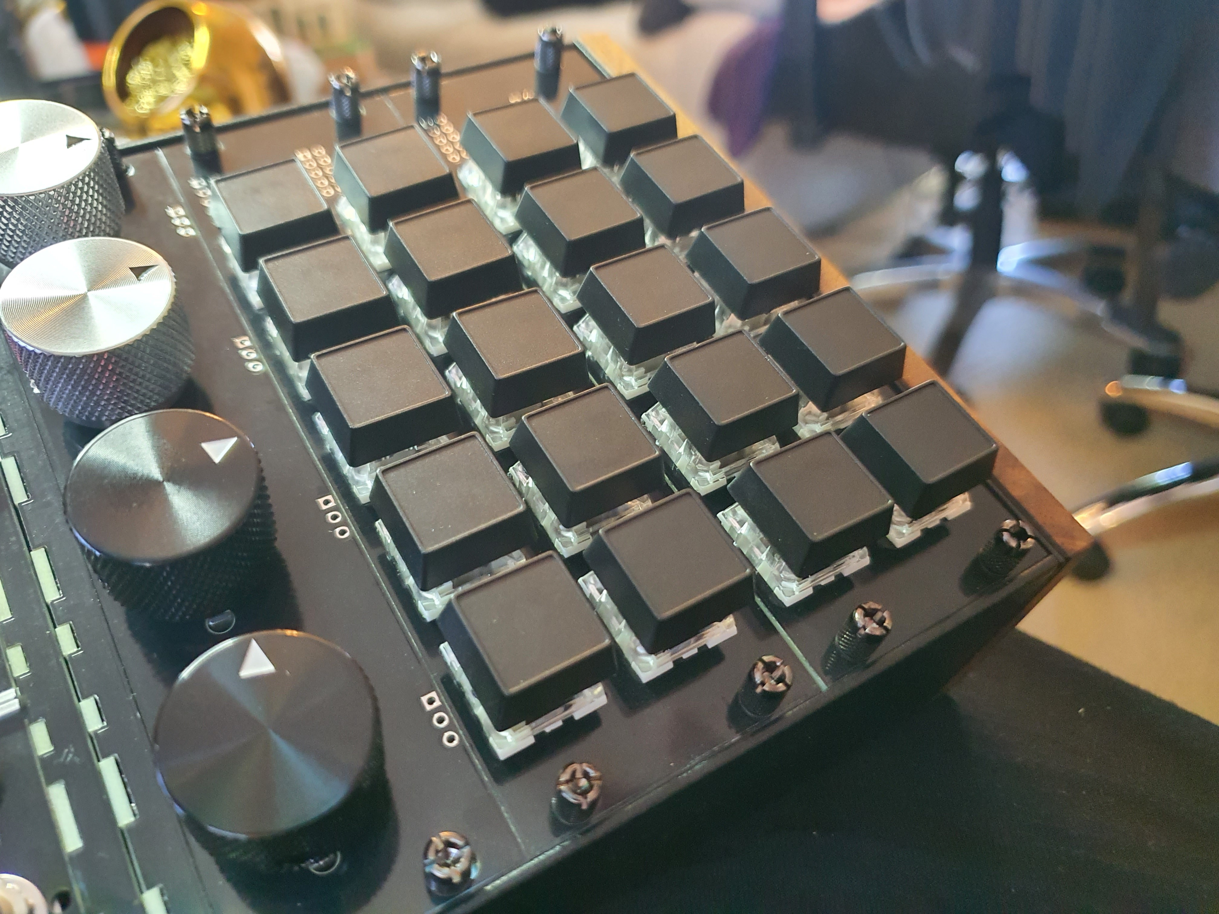
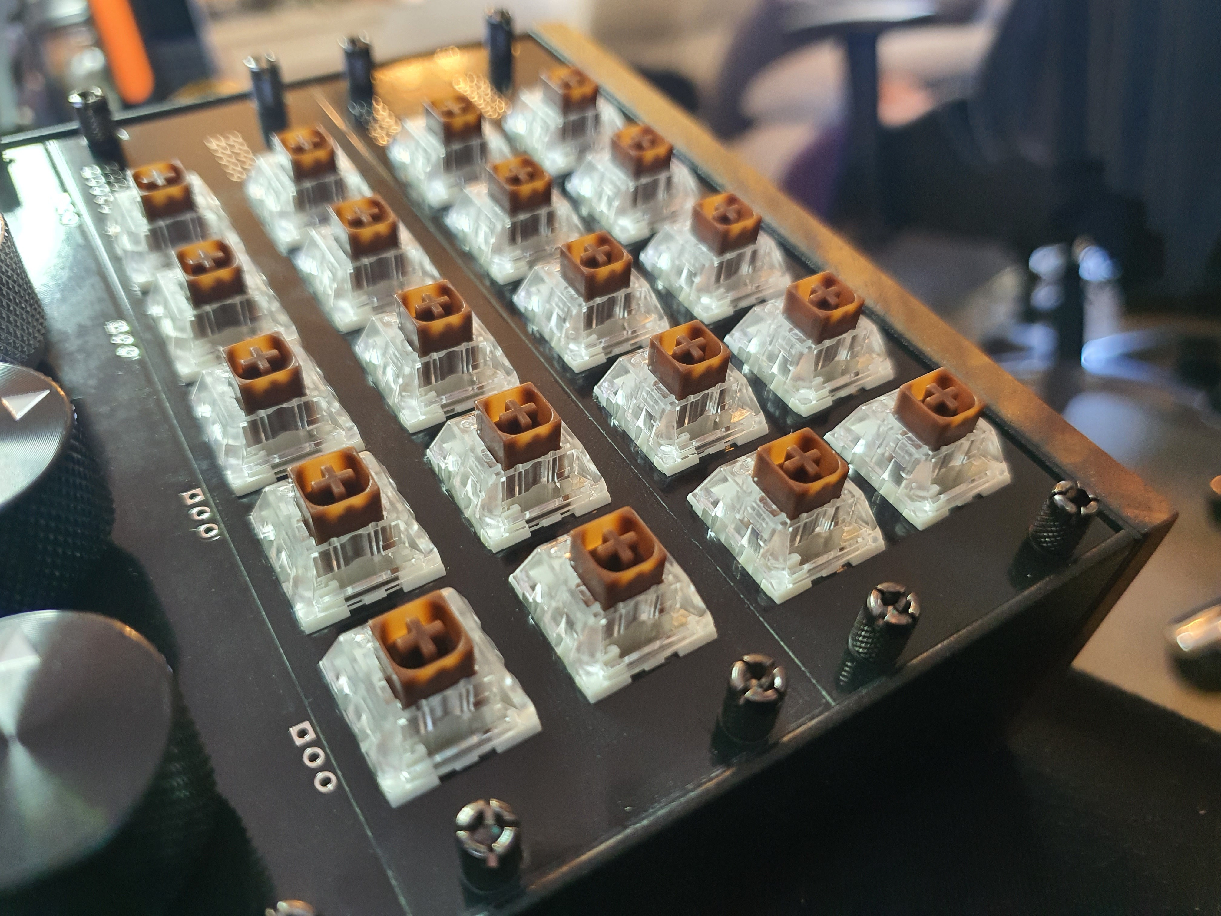
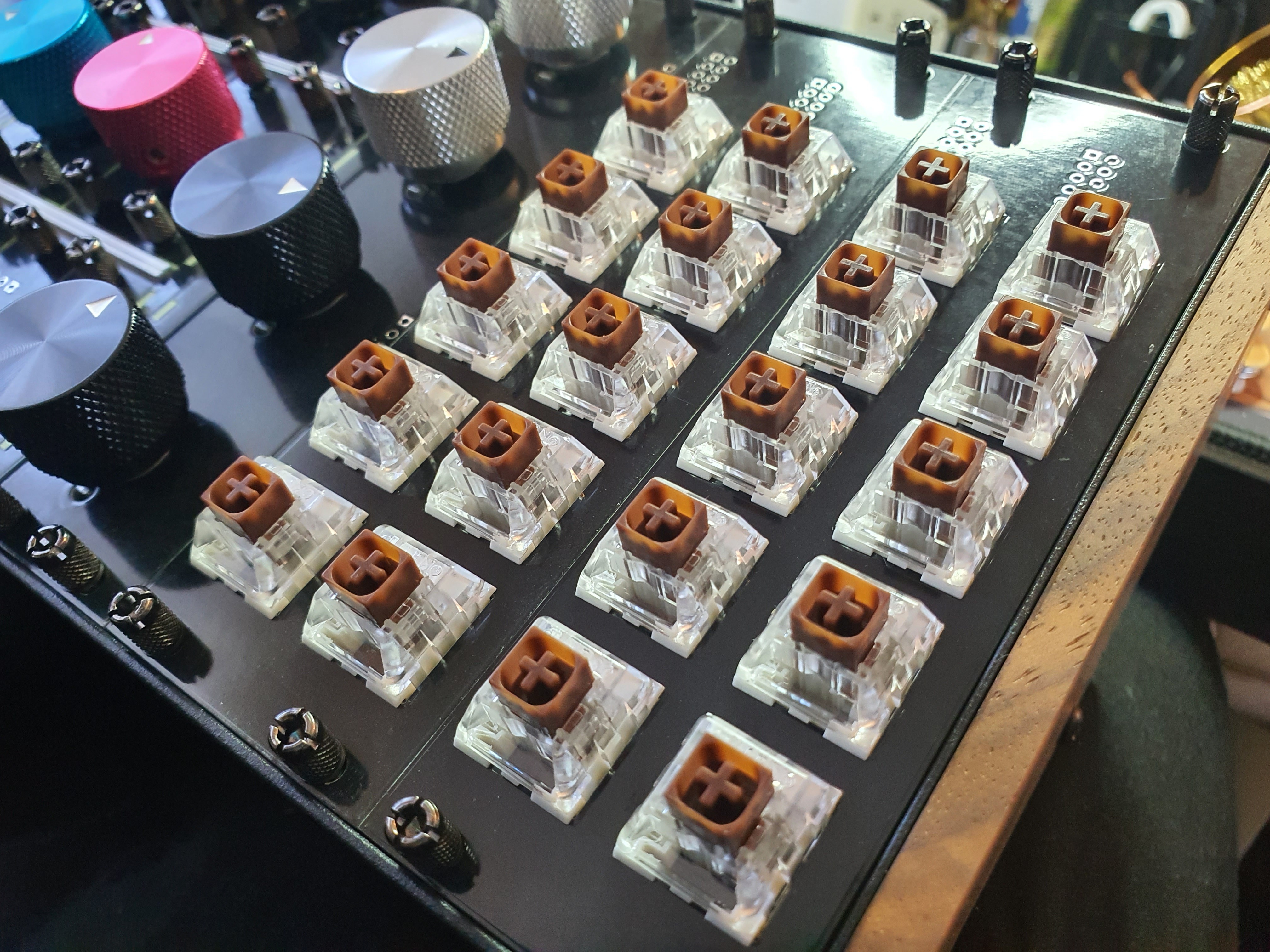
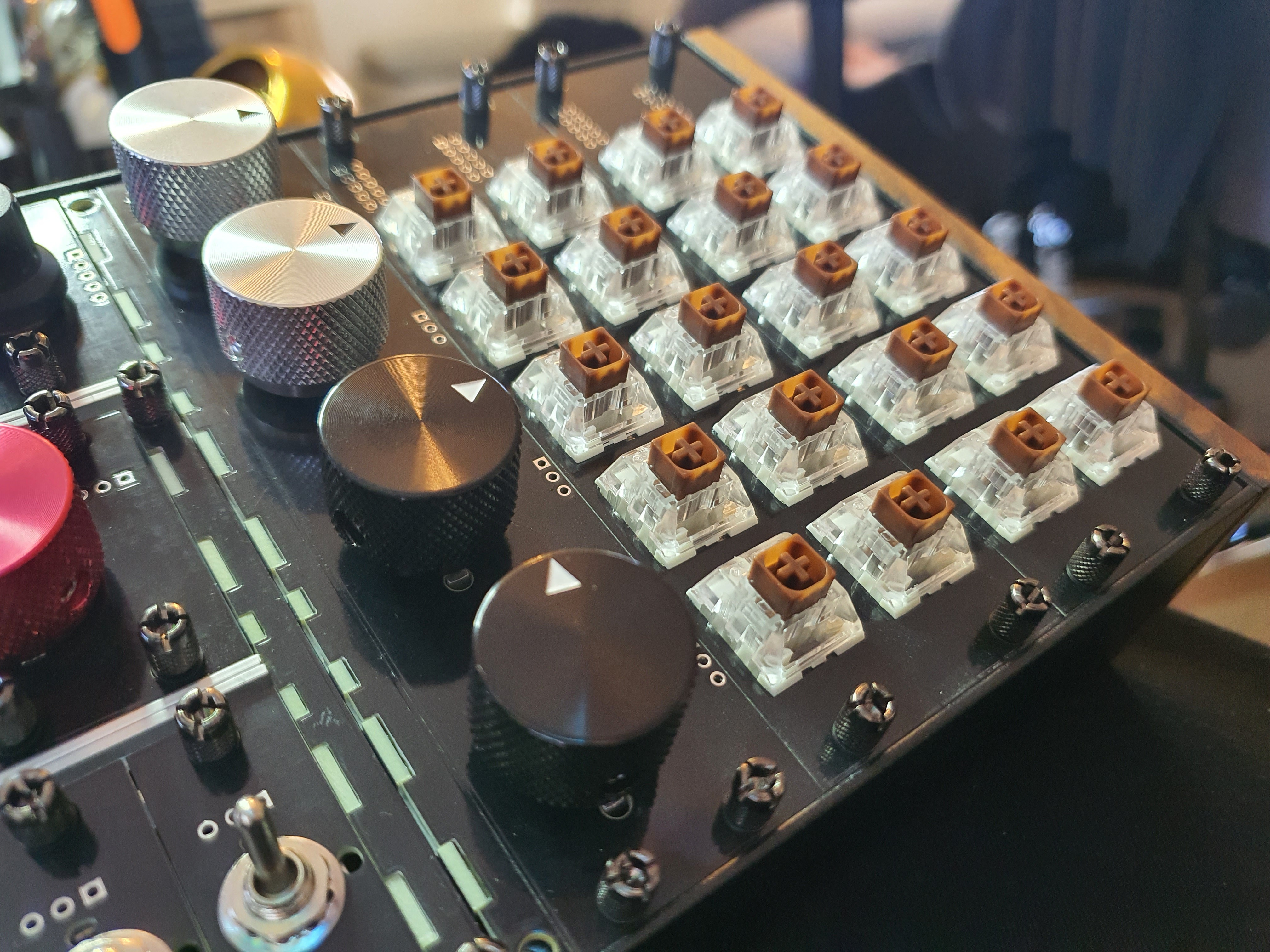
Anyway, now that I have the rail adapters done, I can screw in each of the individual electrical components into their respective PCB plates, and this is what that looks like:
Oooh isn't that just pretty!
It's got the sauce, as the kids say.
I'd post that to my aesthetic tumblr under #tactile.
actually, I might just do that too brb.
This is where this project started to get interesting! (for me)
I woke up one morning to a rather intriguing email from an interested party; they claimed they were a representative from a company called PCBWay, and were offering me a sponsorship opportunity.
This had me excited for several reasons;
1) How did they find out about me? I had only just been uploading the project to github for a little while, and definitely had not advertised it anywhere on social media; do PCBWay employees just go trawling through new GitHub pages to find interesting things? I was curious. I didn't even start this Hackaday log until long after they'd contacted me.
2) I have never been sponsored for anything before. I'm just some shmoe, I didn't even finish High School! I've had the same job for a decade, I don't hang out anywhere exciting, I definitely haven't been hanging out around people of enough import to have sponsorships. I was excited!
So I sent an email back saying "yes please!", and here we are. Exciting!
PCBWay promised to send me the PCBs I ordered for free, and in return I was to give them "some kind of shout-out or review". They were really quite vague about it, which I'm nervous about, but also that's pretty neat? Quite hands-off. Anywho-
The first PCBs I ordered for this project (see Log#2) were from JLCPCB, and ordering from them was... interesting. Manually generating the gerbers was tedious, but at least their documentation was thorough. The PCBs were shipped in a timely manner, and didn't have anything wrong with them, so I must have done the gerber generation properly, but it was still quite scary! I liked their colour options, and they even had thickness options which I toyed around with, since technically the Eurorack standard has 2mm-thick plates. In the end, I stuck with the default 1.6mm thickness, since I'm already designing 2U components so sticking perfectly with the standard doesn't really matter any more, and the extra 0.4mm won't really affect anything. There's plenty of extra space in the rails to accommodate the extra screw length leftovers.
I've also used OSH Park before (for different projects, many years ago), which was much easier (just upload the `.kicad_pcb` file), but were also more limiting; purple only, no thickness options, and no custom fonts! They do have the best PCB preview options of all of the ones I've tried so far though, so they're great for a first-timer. Nice large preview windows showing what either side of the PCB will look like! Very good for peace-of-mind.
PCBWay, on the other hand, is rather quite a lot more user-friendly compared to JLCPCB, and just as customizable; Not nearly as limited as OSH Park, and nearly as easy to use.
After receiving the go-ahead for the sponsorship, I looked into how to order from them, and it turns out they have a nice little one-click button you can install directly into KiCAD that will do all the gerber generating for you, and open an order page in your browser with it all uploaded for you! very cool. I didn't even have to look for it very hard! I opened KiCAD, opened the Plugin And Content Manager, and searched "PCBWay", and there it was! Installed that with no trouble, and now there was a button in the PCB Editor that, when pressed, opened a browser window with an order of the current PCB design ready-to-go! Love that. I'm probably just going to keep using PCBWay just for that, to be honest.
Can't get a more glowing review from me than "It Just Works", and boy howdy it just does. Neato!
I debated going with 2mm thickness for the PCBs this time again, but again the price was a factor- the 1.6mm thickness PCBs are just so much more common that their prices are so much cheaper than every other option, and again the extra 0.4mm for the screws won't be a problem. Sure I'm getting these ones for free, but Liam, my lovely liaison, doesn't have infinite patience, and I'm sure if I, some rando who happened to get his attention one day, came to him with a $500 bill for...
Read more »Since I'm trying to fit 1U (and now 2U) modules into a 3U case, I'm going to need some kind of adapter. There were a few I could find online by searching Modular Grid, but none of them were flexible enough or in stock enough for me to humor them as real alternatives. Instead, I decided I would make my own!
I had an epiphany one day, while designing some of the modules for this project. I was toiling away inside blender, doing what I do and hyperfocusing on what would probably never come to fruition, when it happened.
I stopped what I was doing, sat back in my chair, and just like that, I had it. I moved my hands together, crossed each finger over the other; that was it! I would make a fingerey-sandwichey-thing with PCBs at right-angles to each other, and use solder pads to hold it together like glue. Just like one would with a laser-cut wood project!
I'm sure there's a word for what this is, and I'm sure I'm not the only one to have this idea, but it felt magical to have come up with the idea on my own, even if it wasn't a unique one.
I got to googling, and found some nice DIY Eurorack case rails made by SynthRacks. There was some thorough documentation (which I love), with lots of pictures! Very nice, I thought. There are even custom HP length options! Perfect.
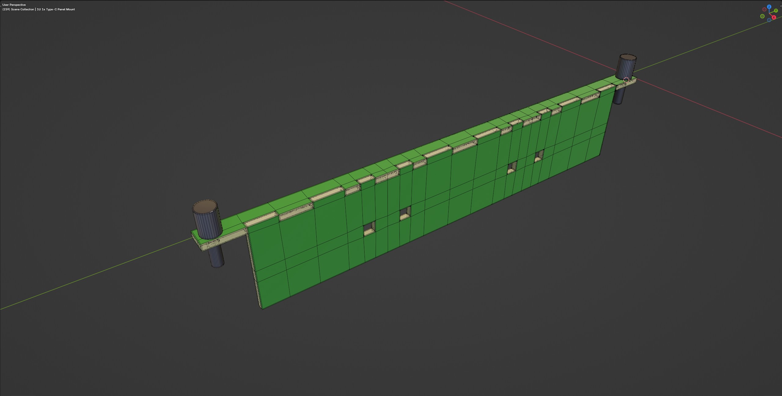
I couldn't find exact measurements of where the mounting hole would go, so I designed a slot instead of just a hole, for the screw to mount the rail to the PCB, and designed groves for the PCBs to mount to each other, and added some small surface-mounted areas for the solder to attach each part of the PCBs together. I found some nice screws on AliExpress with a recessed hex slot inside the shaft, so the screw had a much slimmer profile; this was important, since I wanted the adapter to take up only a single HP for each side of the adapter; this is what the alternatives I was looking at ordering used, and I didn't want to be shown-up by someone else!
Here's what I came up with:
Now it was just a matter of picking the right HP lengths for the modules I wanted to fit in them, and Order the parts, and hope I didn't screw anything up, and that my weird hack actually works! No big deal. We shall see.
Finding the parts to use, and making sure those parts fit witin the Eurorack standard was a fun and interesting challenge.
Following the Eurorack sizing guides from Doepfer and Intellijel, I could tell that I have only a certain amount of space in each module, if I want to be able to use a normal Eurorack case to keep it all in once it's done.
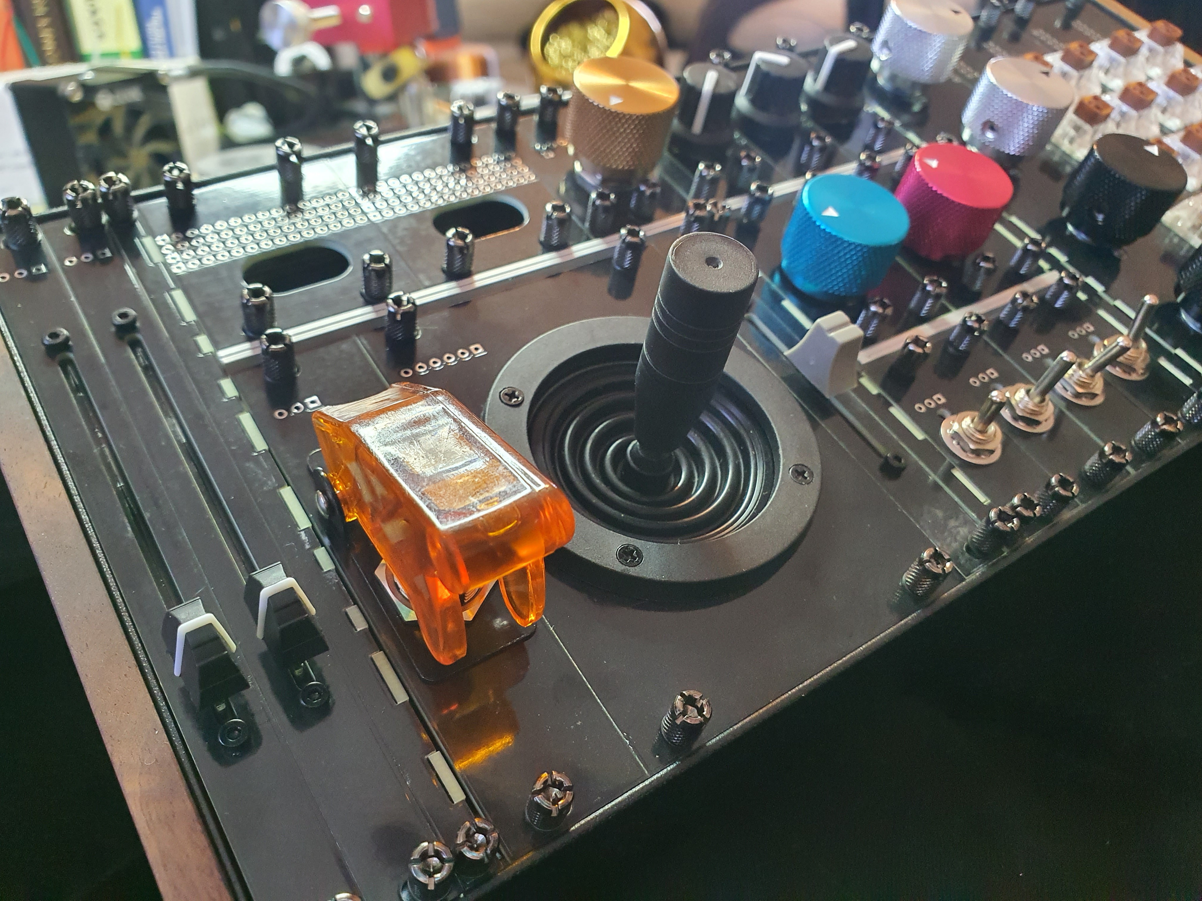
Some parts, like this Motorized Slide Potentiometer would be quite fun, but sadly are too long for a standard 3U module; I would have to find (or make) a case that was 4U in height. I didn't want to go quite that far for this project.
Other parts, like this smaller 75mm Slide Potentiometer fit just fine in 3U.
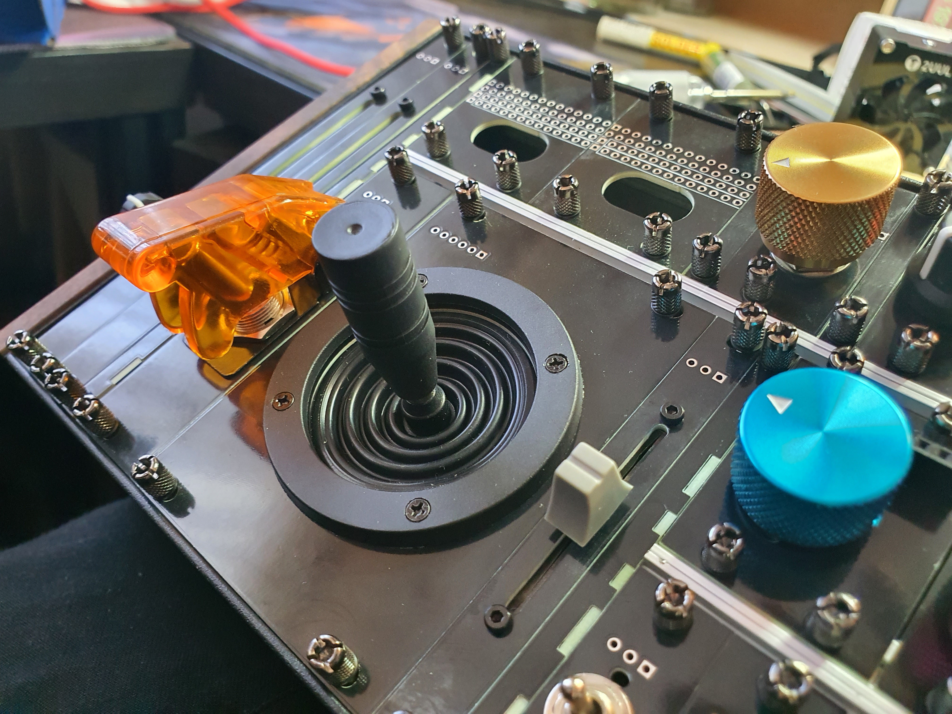
Some other parts would fit in 3U, but there would be a lot of wasted space around them, like this Mini Analog Joystick.
Perhaps if I smudge the Eurorack format a little bit? keep 3U and 1U modules, but also have modules that would fit into 2U? I mean, if I'm putting 1U modules into a 3U case, I'm going to have 2U left over... and sure I could fill that with two more 1U modules, but why not just have some 2U modules? That could be fun!
I'd previously ordered some PCBs from several places for other projects, and knew intuitively that what I was after for this project could easily be made and shipped to me for cheap as PCBs, and would quite easily fit the bill of requirements for an Eurorack module. by buying a Eurorack case, and filling it with PCBs-as-plates for the modules, and mounting the Electrical components directly to them, I could get away with a minimal amount of manual labour. All I would need do is solder it all together, and I wouldn't need to faff about with a custom 3D-printed-anything, or manually drilling holes, or any of that fun stuff. Just made-to-order goodness.
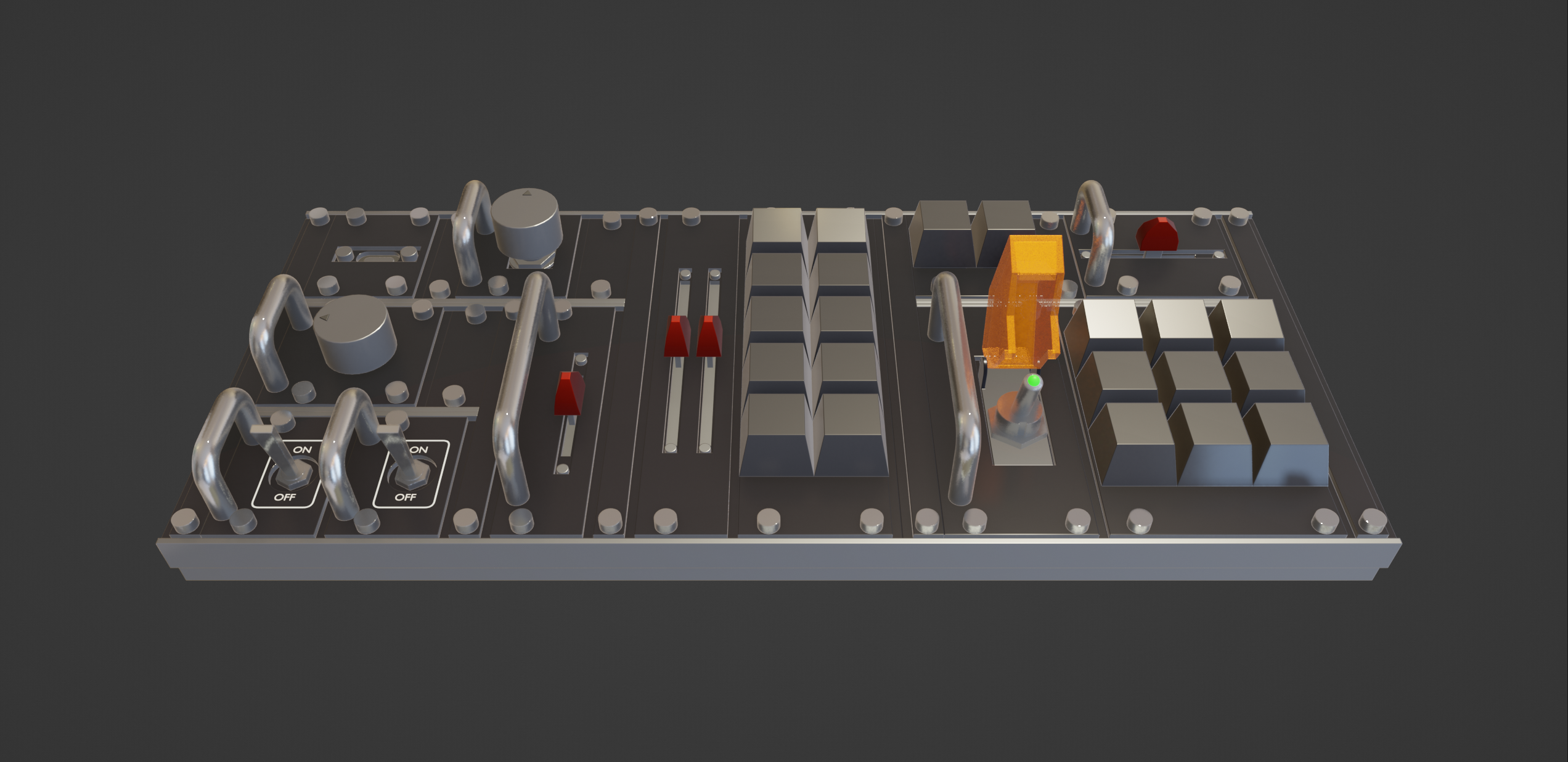
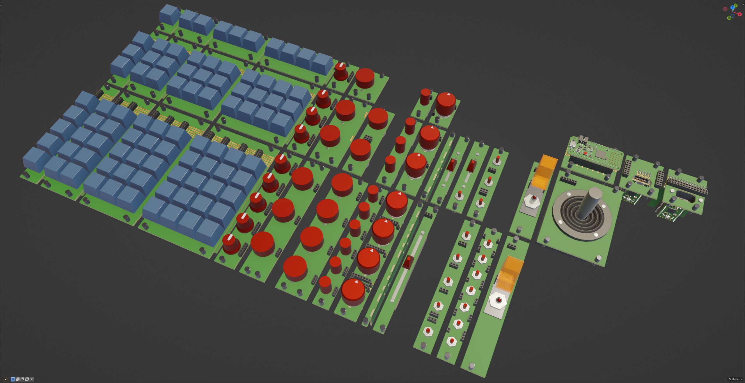
I created some crude approximations of some components I found online (mostly AdaFruit, and AliExpress), and imported them into Blender. These will be my playing blocks.
I then designed some rough outlines of the Eurorack rails.
Making frequent comparisons to the sizes of the front face of the modules on the Doepfer website, and the sizes of the PCB on the Intellijel website, I could ensure that whatever component I designed around would fit in the spaces I wanted to put it.
I played around with positioning and sizing of the components, I came up with several sizes of module that fit each of the parts I wanted to use. This is what they look like:
Since I'll be wiring this all up by hand, I only really have to worry about whether there will be enough finger space between each component once it's all assembled. So long as the part fits, I can add more blank spacers between the parts if I find it's all too cramped.
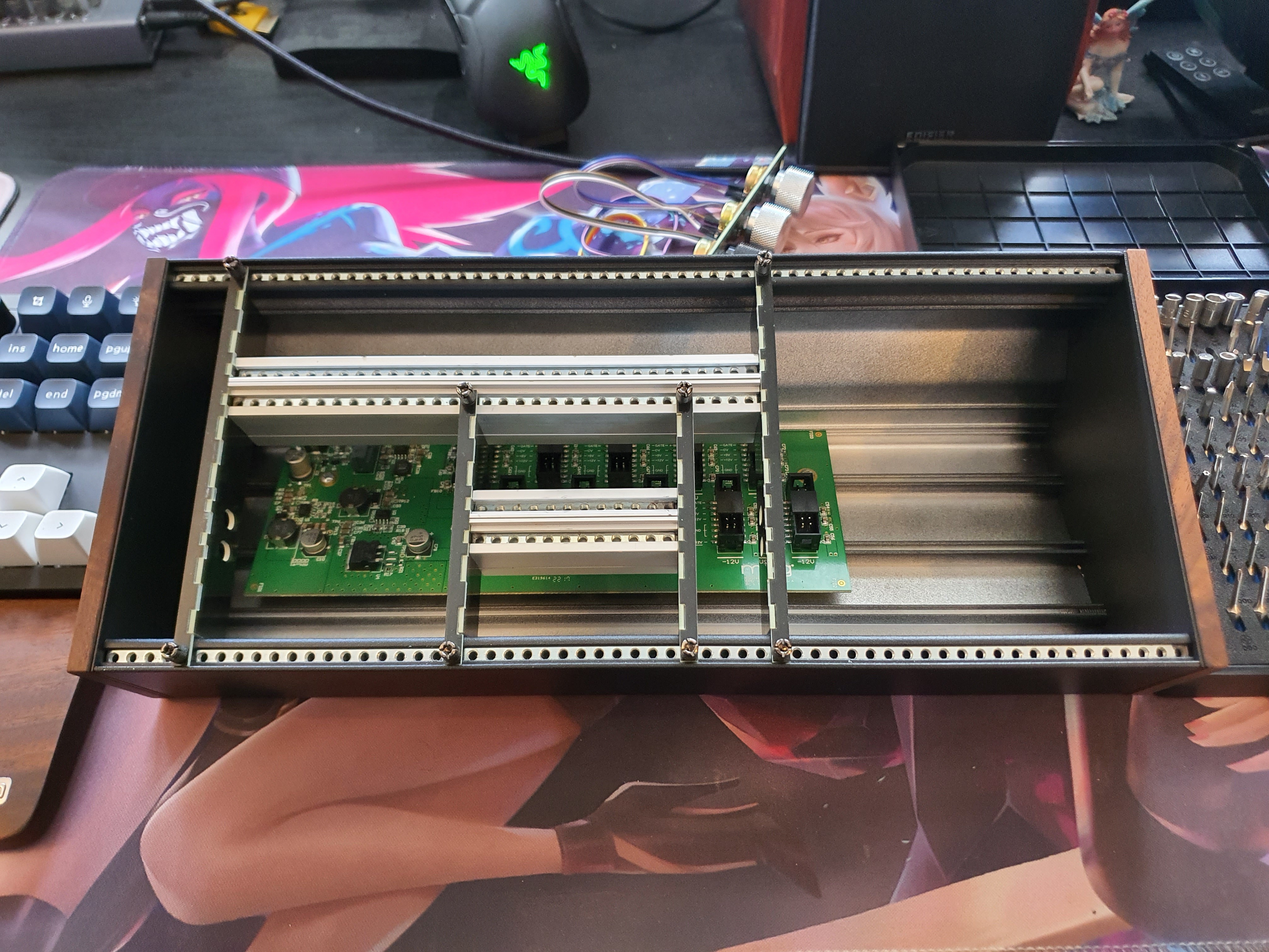
The first PCBs arrived last week, as did the case I ordered from a local Music store!
Look how perfectly they fit!
Next steps will be designing more modules which support more types of Thing (as cool as Cherry-MX keyswitches are, they can't do everything).
Fingers crossed the next few parts fit too!
Two things are true:
Maybe i want more dedicated buttons while I'm playing this game, or maybe i want more knobs or sliders for that game. Maybe i want some toggle switches while I'm playing this, but those toggles would be useless while i play that.
There are so many considerations to keep in mind while designing a buttonboard. How do you decide what to include in yours?
Why make the choice at all?
If you don't have to choose, you can do it all.
Maybe it's because the format was on my mind, or maybe its because the format lends itself well to a modular workflow (because it is one), or maybe its just because the hardware is abundant and there are many cases and screws and other such hardware to choose from, maybe its because the documentation for said hardware specifications is abundant.
Maybe it's because the size is Just Right.
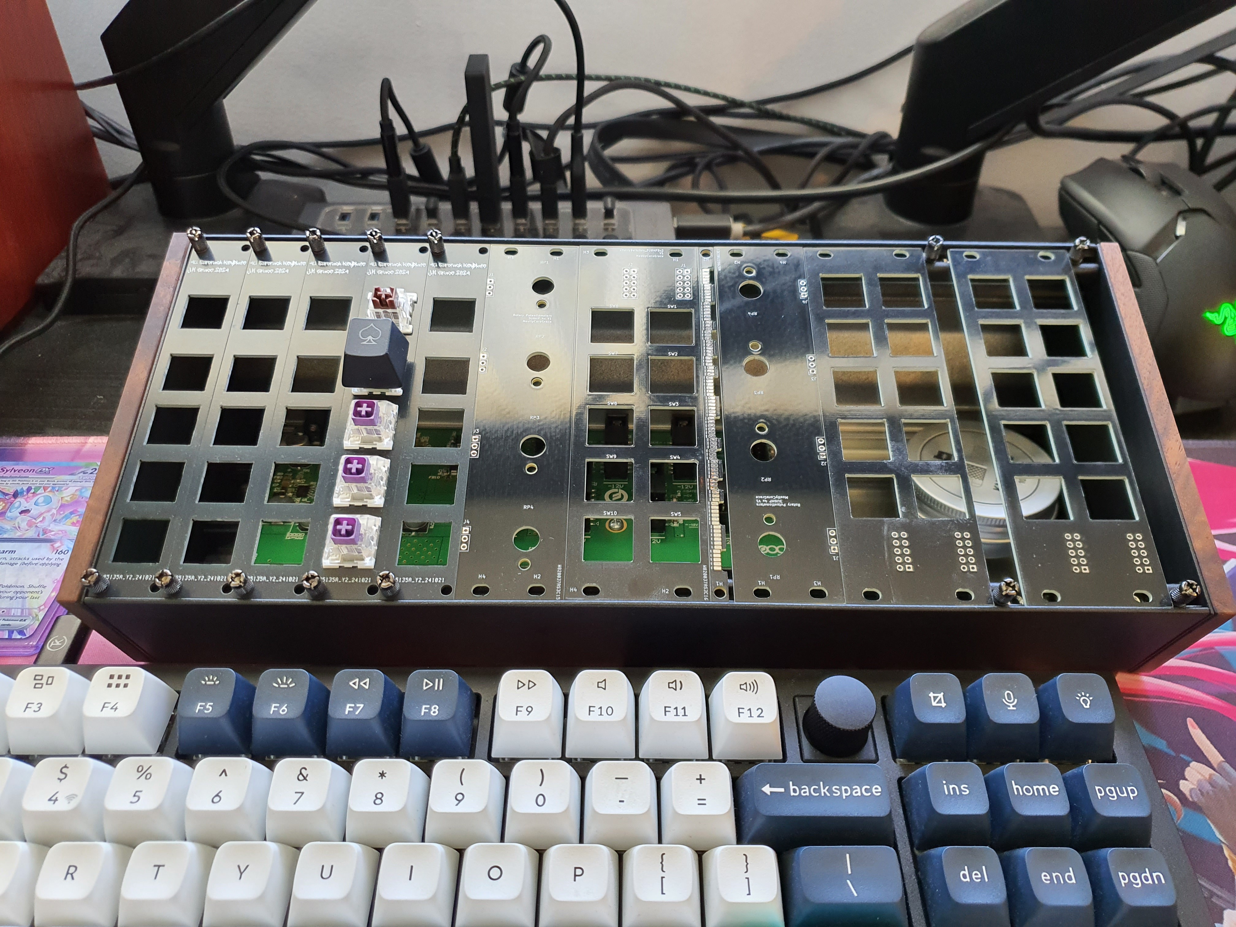
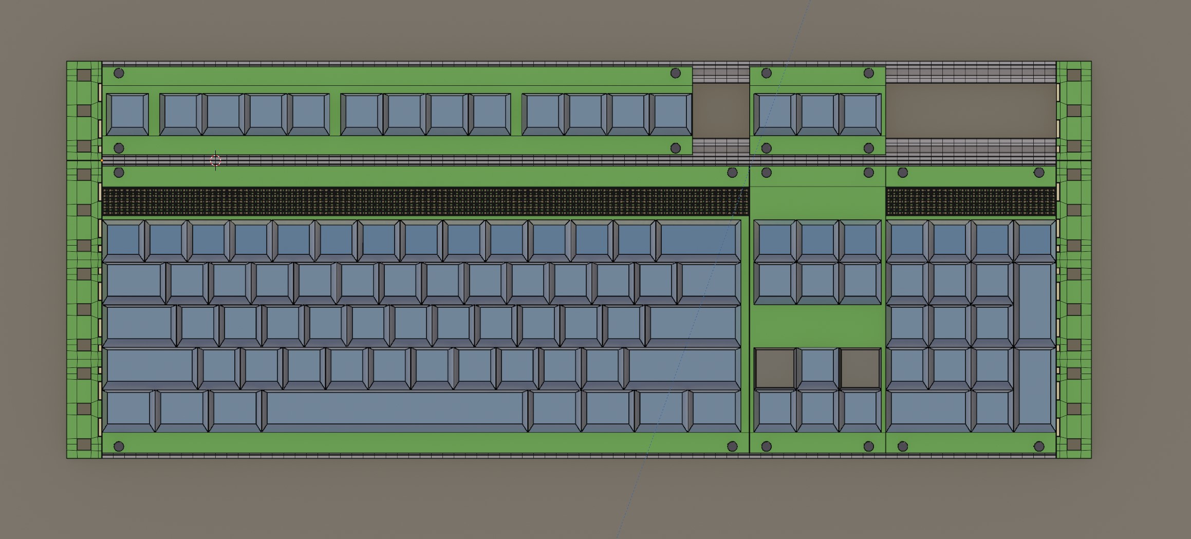
Take a look at this, an early mockup I put together of a complete 104-key keyboard fitting inside a standard 19" frame. 3U for the alphas, and 1U for the function row:
Look how perfectly it fits!! I'm sure someone who understands the Imperial measurement system won't find this interesting, but as someone who only ever uses Metric, this just feels so wild to me. Sure, the function row and ESC keys are pretty far away, but let's ignore that. A 1U intellijel-compatible module can fit a rotary encoder, a toggle switch, a cherry-MX or Choc-compatible keyswitch, or a rotary selector. A 3U Eurorack-compatible module can fit 5 (or 6) Cherry-MX or Choc keyswitches, a linear potentiometer, various toggle switches, rotary encoders, rotary selectors, etc.
There's also the question of why I went with an existing standard, instead of coming up with my own. Sure, if i went with my own standard, i could make the sizes better suit the parts I intend to use- an Eurorack module leaves a lot of 'wasted' space to the rails, and lots of gaps between parts as 1U is too small for some of the parts, and 3U is too large for some of the parts- but the alternative is i have to make my own standard.
many people have tried to make their own standards before- but they've all of them ended up being way too over-engineered. I've seen projects that used pogo pins, and a microcontroller that has firmware to allow hot-swapping components, and custom 3d-printed shrouds, and- its a lot. It's too much. It doesn't have to be that complicated.
You don't need to have support in the firmware for hot-swapping components, because the only way to bind an action to an input in a game is to press the button, and if you can't press the button, you can't bind to it. There's no need to de-register the firmware for the button if you can't bind to it.
You don't need to 3d-print custom cases if you can use an existing case, and simple PCB plates.
You don't need custom pogo pin matrices to combine components if you just jam all the cables behind a façade.
And so, Eurorack.


 Peter Lyons
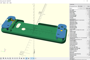
 Maave
Maave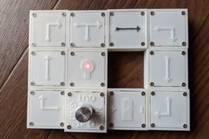

 deʃhipu