 Cora
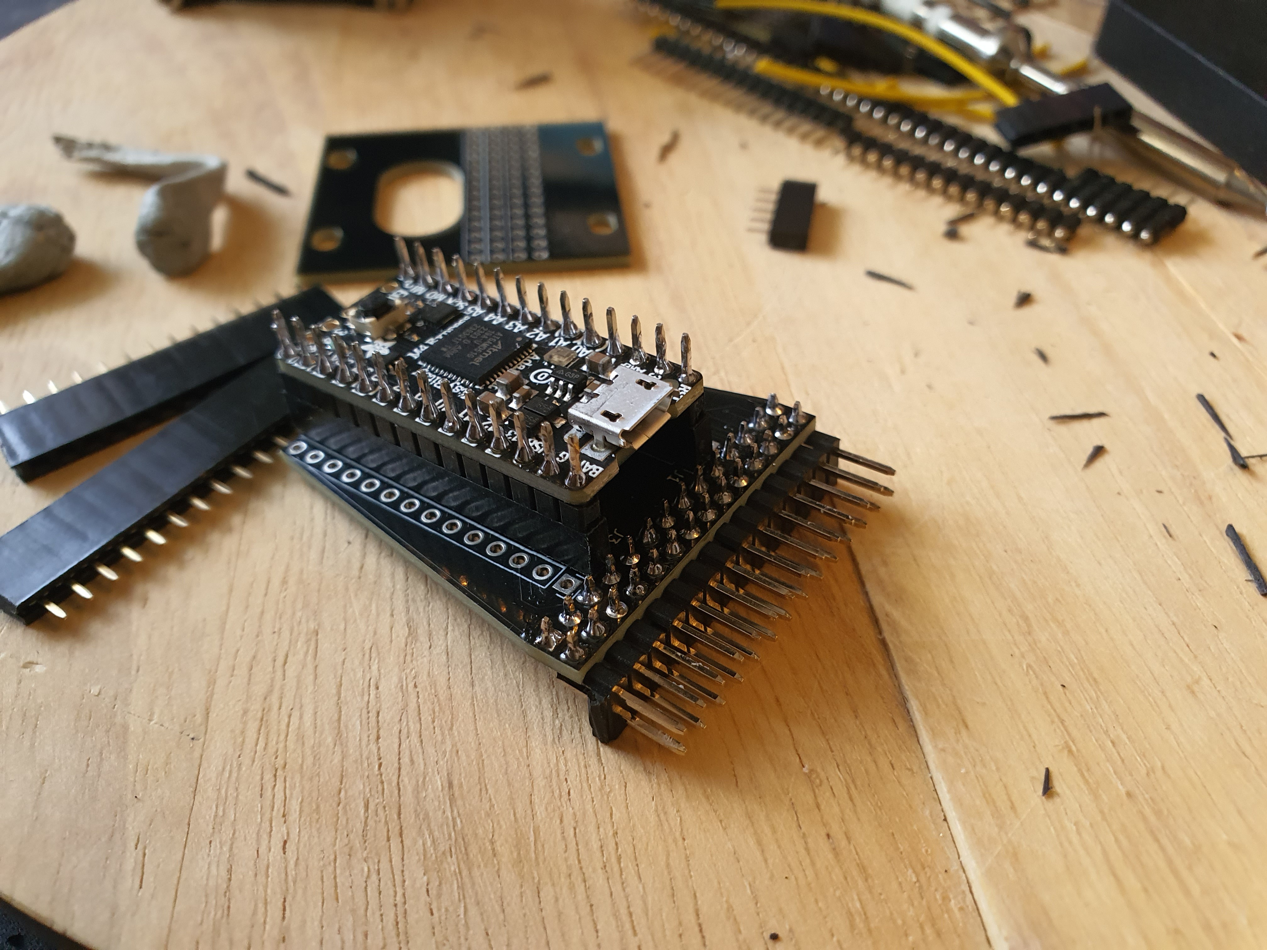
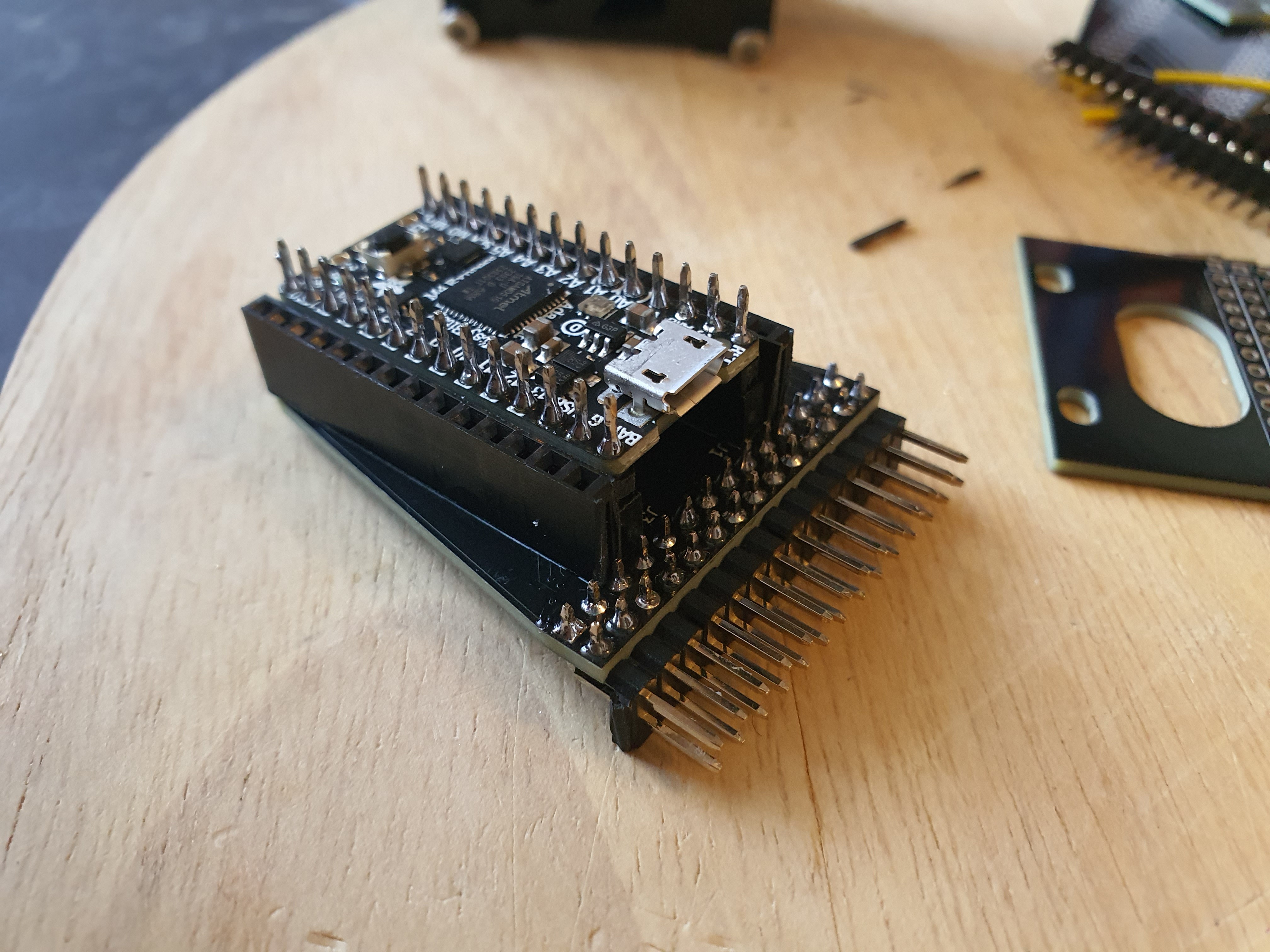
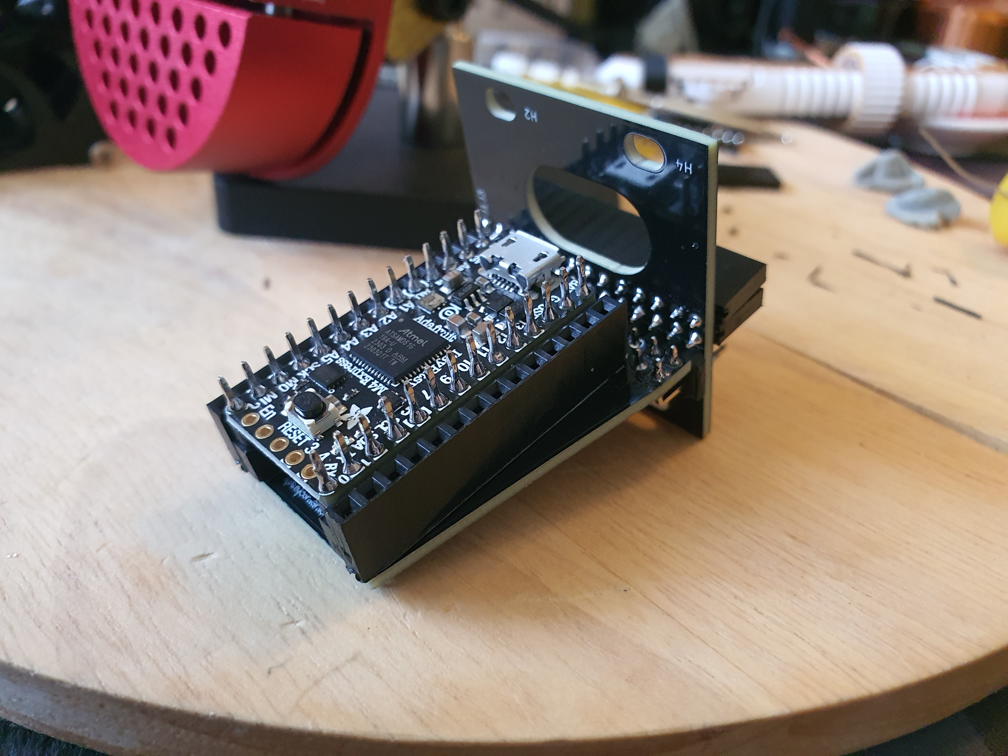
CoraWhen designing the components, I wanted the USB controller to be a part of the design, instead of just hidden inside the case.
Part of the aesthetic of this project is to mirror the beauty of the Eurorack scene by making the chaotic wiring a part of the design, and that means the headers of the controller need to be just as exposed as the components I'm connecting to them. Since I also wanted to make sure none of the exposed sections of the design had anything poisonous on them, that meant I couldn't simply have the controllers connected flat on the plate with some headers. I briefly experimented with this, but they took up a comparatively large area, meant the attachment points would have to be underneath the controller, and meant I couldn't just have them side-by-side (since the USB connector would interfere with whatever was next to them). So a more... *complicated* solution was required.
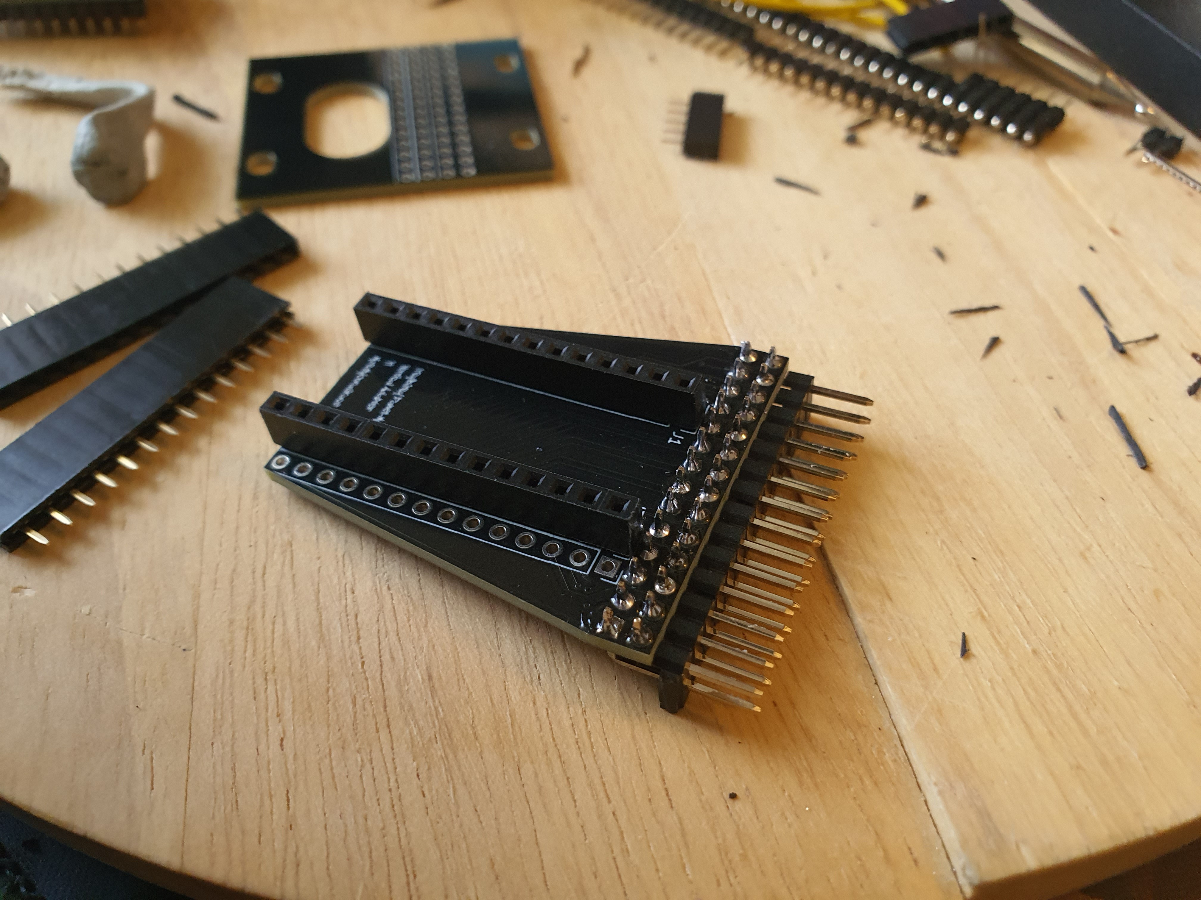
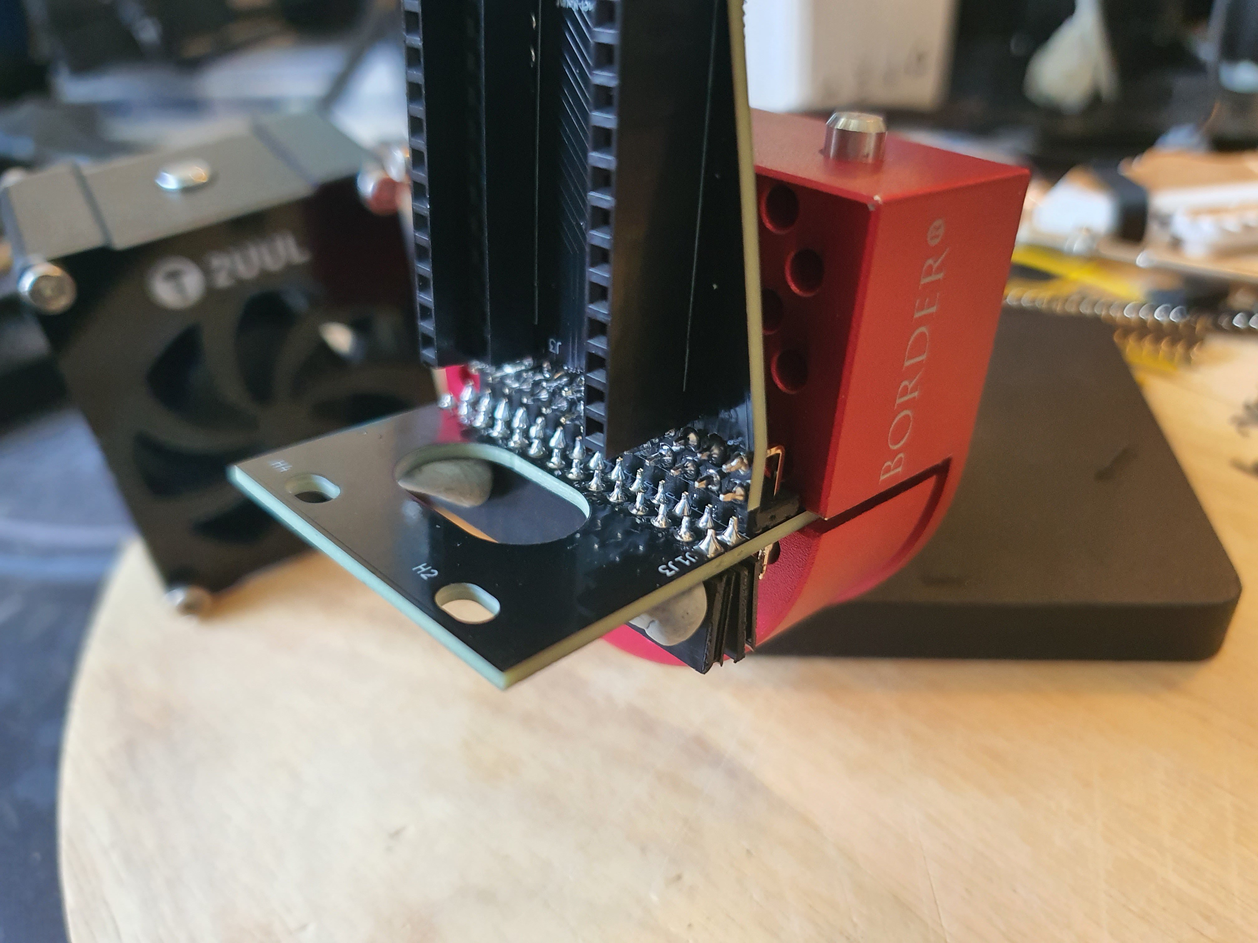
If I used right-angle header connectors as a physical connection as well as an electronic one, I could mount the controller vertically *inside* the case, with the USB port pointing out the same as all the headers, and it would take up much less space! So this is what I went ahead with. Now with the parts in front of me, I wasn't sure quite where to start; the fugue state I designed them in long past, figuring out the correct assembly order such that none of the parts became inaccessible to soon proved challenging.
I managed to get the two sets of female headers, and one half of the right-angle headers, soldered on, and the other female headers and the other half of the right-angle headers soldered on, so all's well that ends well! It sure was a lot of soldering! Gee I sure hope it all works out...
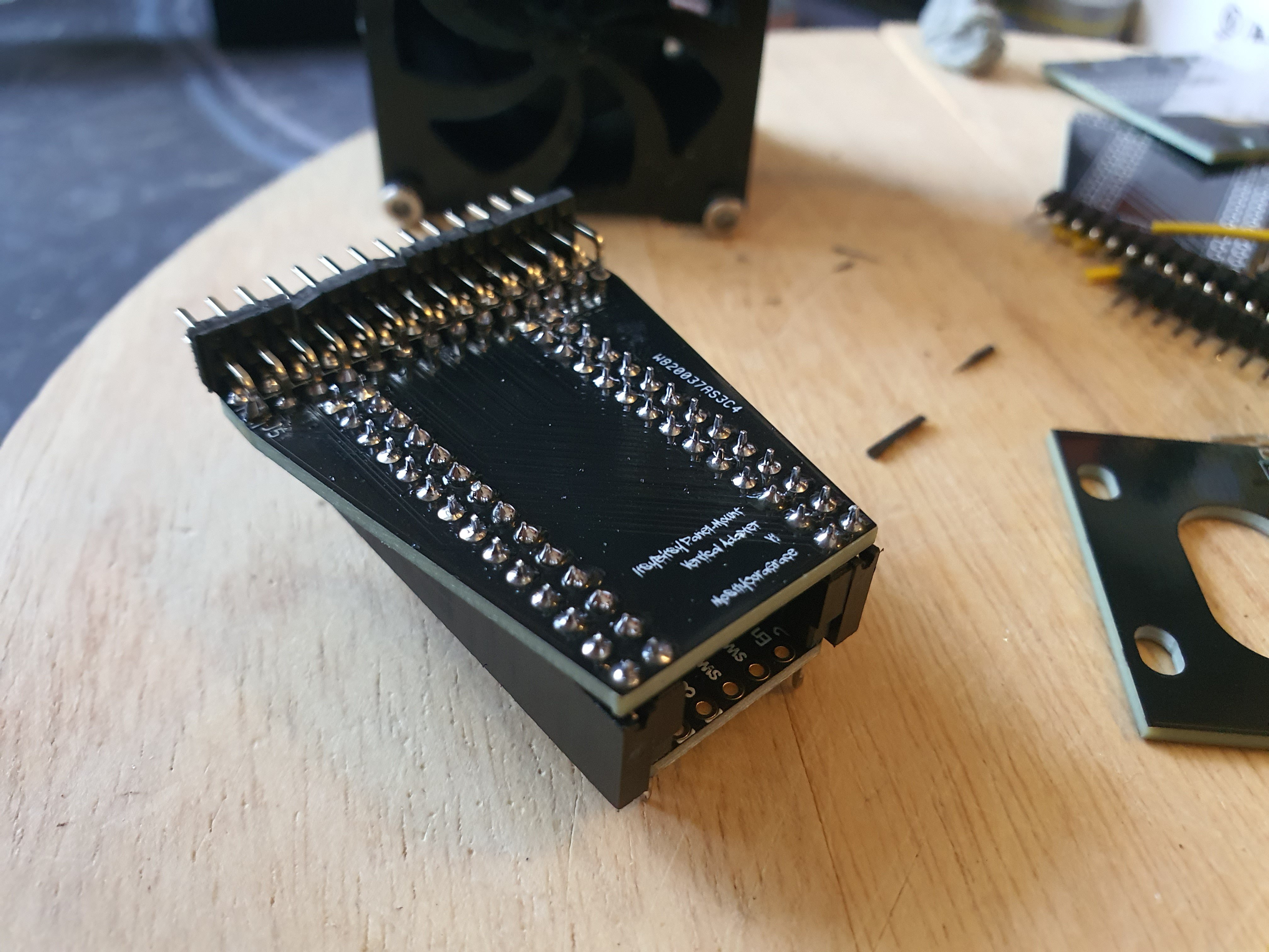


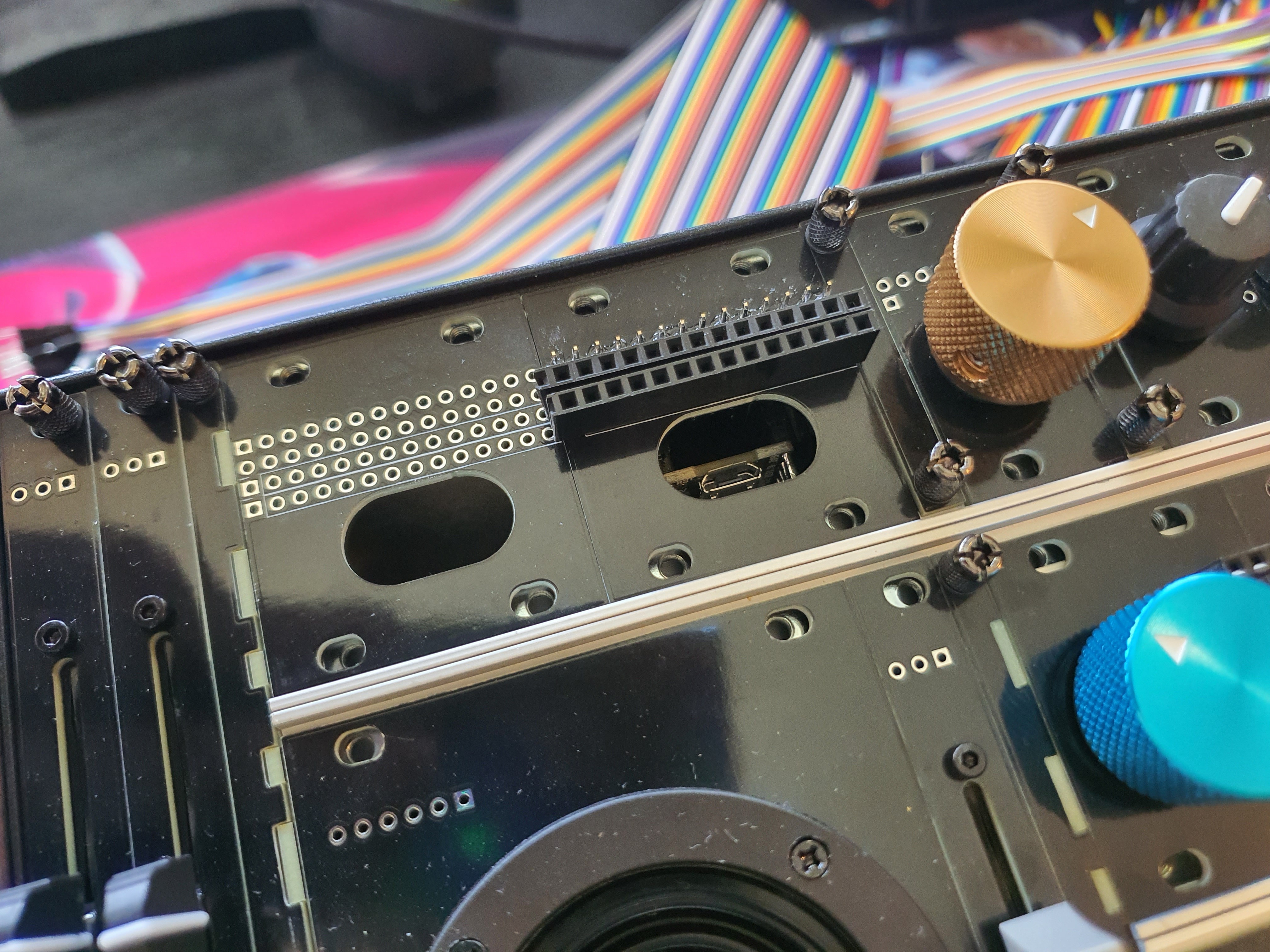
Once I had them assembled, I realized an error! A mistake! A design aspect I had neglected to consider! The headers overlapping the plate next to it I can work around, this part of the design has several blank plates on it for a reason, but the headers are exposed!
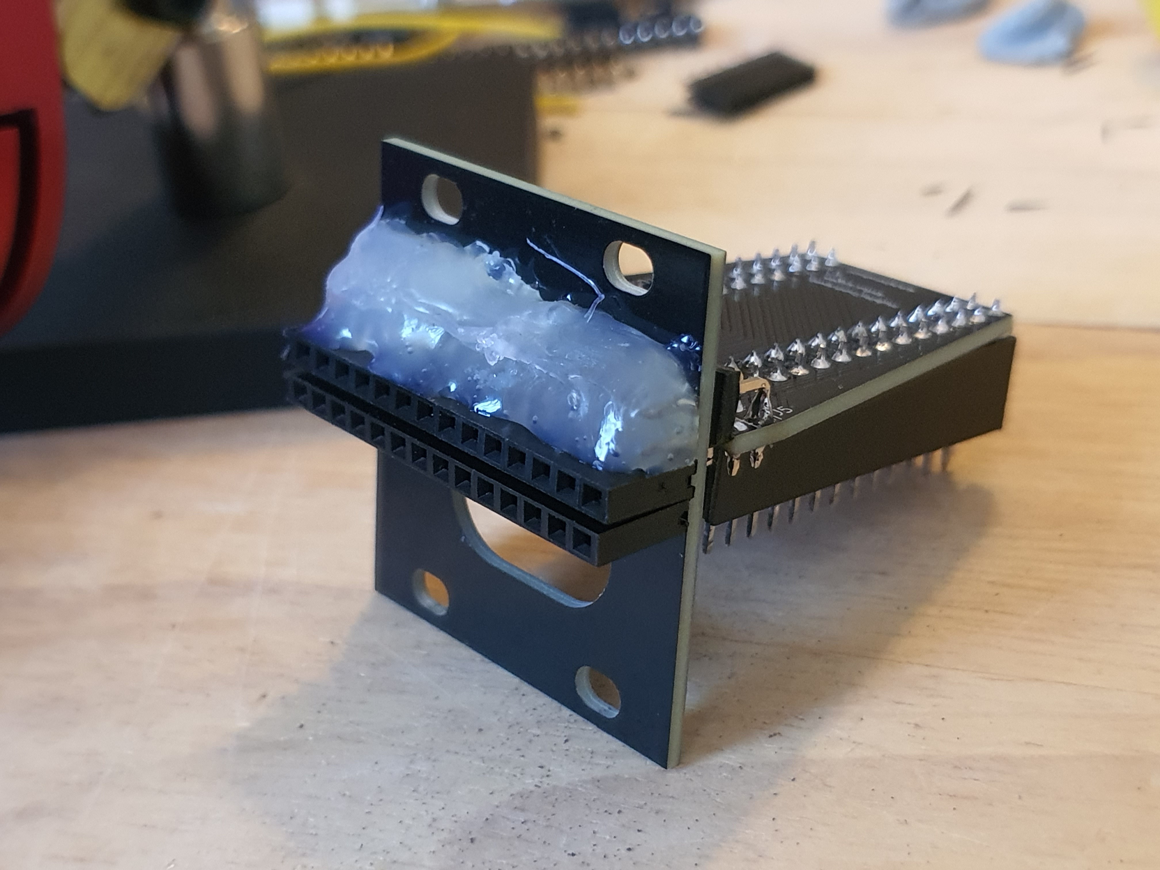
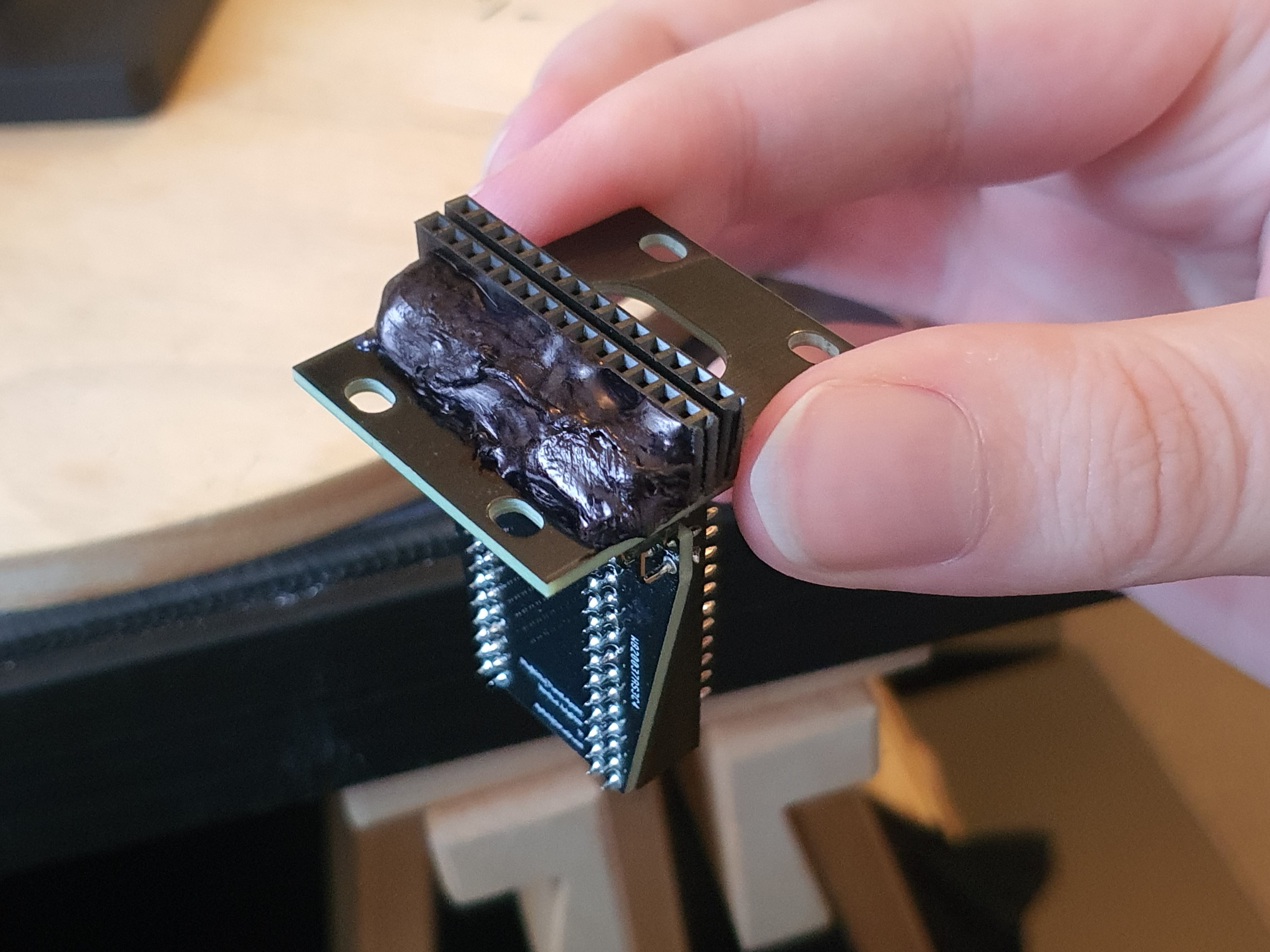
It wasn't that big of a deal, but now that it was in my hands, I could see that the top section of the right-angled headers poked out of the plate, and would expose the toxic leaded solder to my beautiful fingies whenever I were to fiddle with this after its assembly! This I could not abide, and my quick fix was to just... throw some hot glue over them and draw on it with some sharpie to make it look not quite so bad lmao.
This will, thankfully, be hidden behind all the chaos of the wiring once it's all done and dusted, but until then it does look quite comical compared to the quality of everything else so far.
Discussions
Become a Hackaday.io Member
Create an account to leave a comment. Already have an account? Log In.