 Cora
CoraOh boy. This was a journey. Up until now, it had been smooth sailing; things I could do fairly quickly, nice neat updates I could make here and there, fun things to occupy my time. It was not to last.
Now, I'm not electrical engineer; I've not so much as even replaced a mains breaker. I'm barely literate. I dropped out of High School, I can't remember things well, and often repeat myself.
My previous soldering experience includes one keyboard I made from a kit I bought, and one other PCB project many years ago.
This project was ambitious.
It was A Time.
I had fun, yes, but it had its ups and downs. This update will attempt to highlight some of those ups, and some of those downs.
The first Attempt
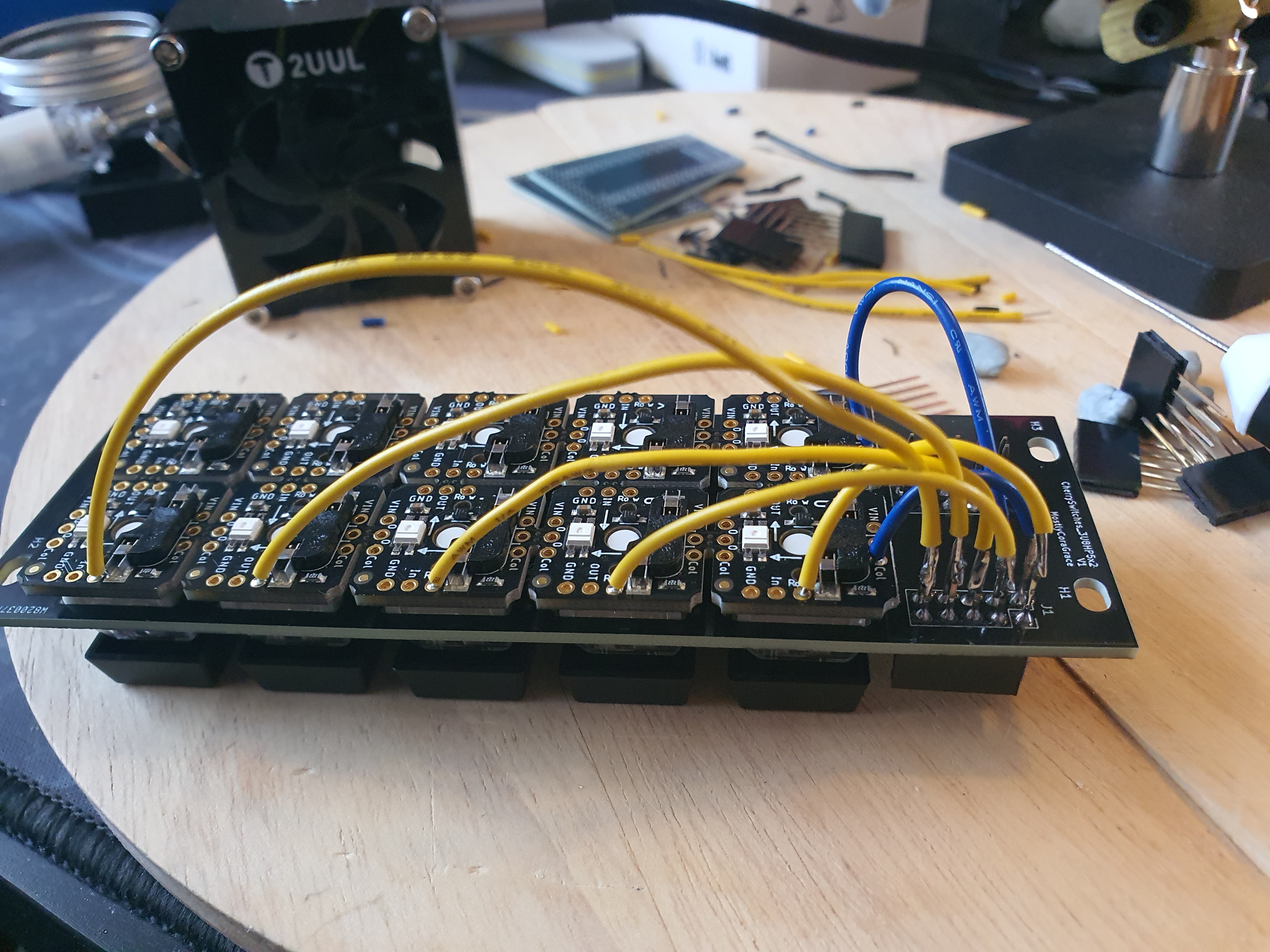
Soldering the first component to the first plate was a big high; cutting the wires to length, trimming the leads, soldering it on. But it was tedious, and I wasn't even sure if I wanted to keep all the wires on top. What if I got to the end, and decided that actually I wanted all the wiring underneath, inside the case? That would be prettier, it would match the aesthetic of a proper buttonboard better, and it would be less prone to breakage. So after finishing this, I decided to change my mind;
The Second attempt
Thankfully, my brain is often bigger than I am. The headers I chose to use for the plates were the longer "Stacking Headers" AdaFruit have; they have a much longer male end, made for attaching several sets of headers together with PCBs between them. This meant I could use header leads on the undersides; solder one end to the component, and use the female end of the header to stick into the plate's header. This meant I could access them from the top, and also that I could unwire them without needing to de-solder them, if I ever decided to keep all the wires inside.
The Other Components
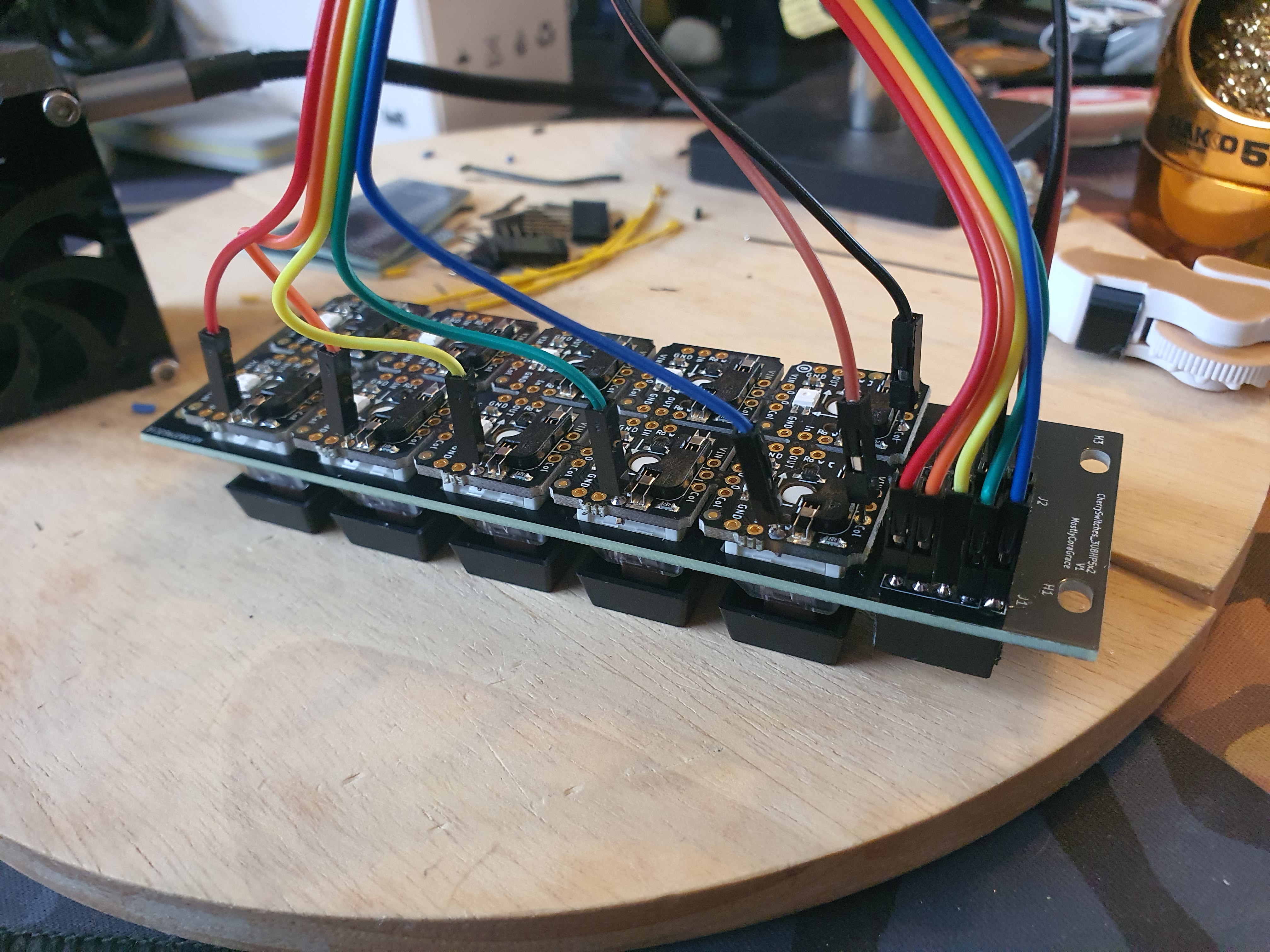
Repeating the process for the rest of the components, using one stripped end of the headers this time instead of soldering directly to the dupont leads like a dumbass, I managed to make some solid progress.

This took a few days! Maybe even a week or two.
I honestly don't remember. I'm writing all these updates in retrospect, since I have ADHD and have no concept of doing things properly. Everything must be done in a rush at the last possible moment, or not at all.
It took a while, regardless. My hands hurt. The tips of my fingers tingled. I googled lead poisoning and its effects comparing leaded solder with non-leaded to make sure I was washing my hands often enough, and ignored the "tingling extremities are a sign of acute lead poisoning" articles, since I knew, logically, that I was just sore from physical activity. I ordered some latex gloves online.
The First Wiring Attempt
So I wanted to test that everything worked before screwing it all together. That's okay; I made all the leads removable for each component, so I can just connect a breadboard to each component via the wires already soldered to them! I'm thinking farther ahead than even I knew. Except now I need to wire the controllers too, and actually while I'm at it why don't I try and fit all the wiring in the case? There's plenty of space in there, surely I can fit the breadboard and the extra-long wires all in there! Lets give it a go.
Except I didn't consider the height of the dupont wires when I designed the 1U plates for the controllers:
No matter, I can solder male headers directly to the wires, at a right-angle, and make my own dupont wires! I'm a genius!
Yeah, that works just fine.
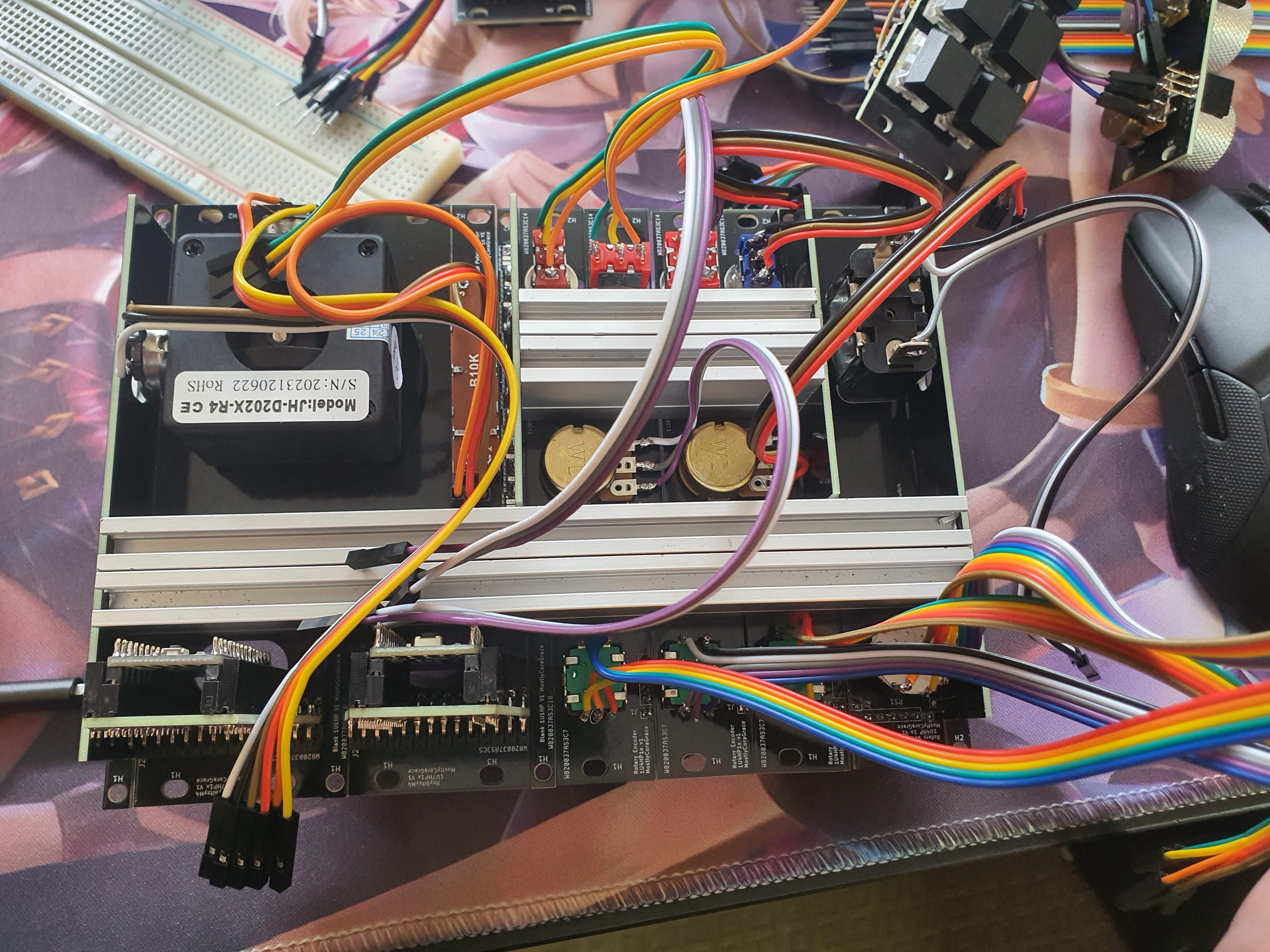
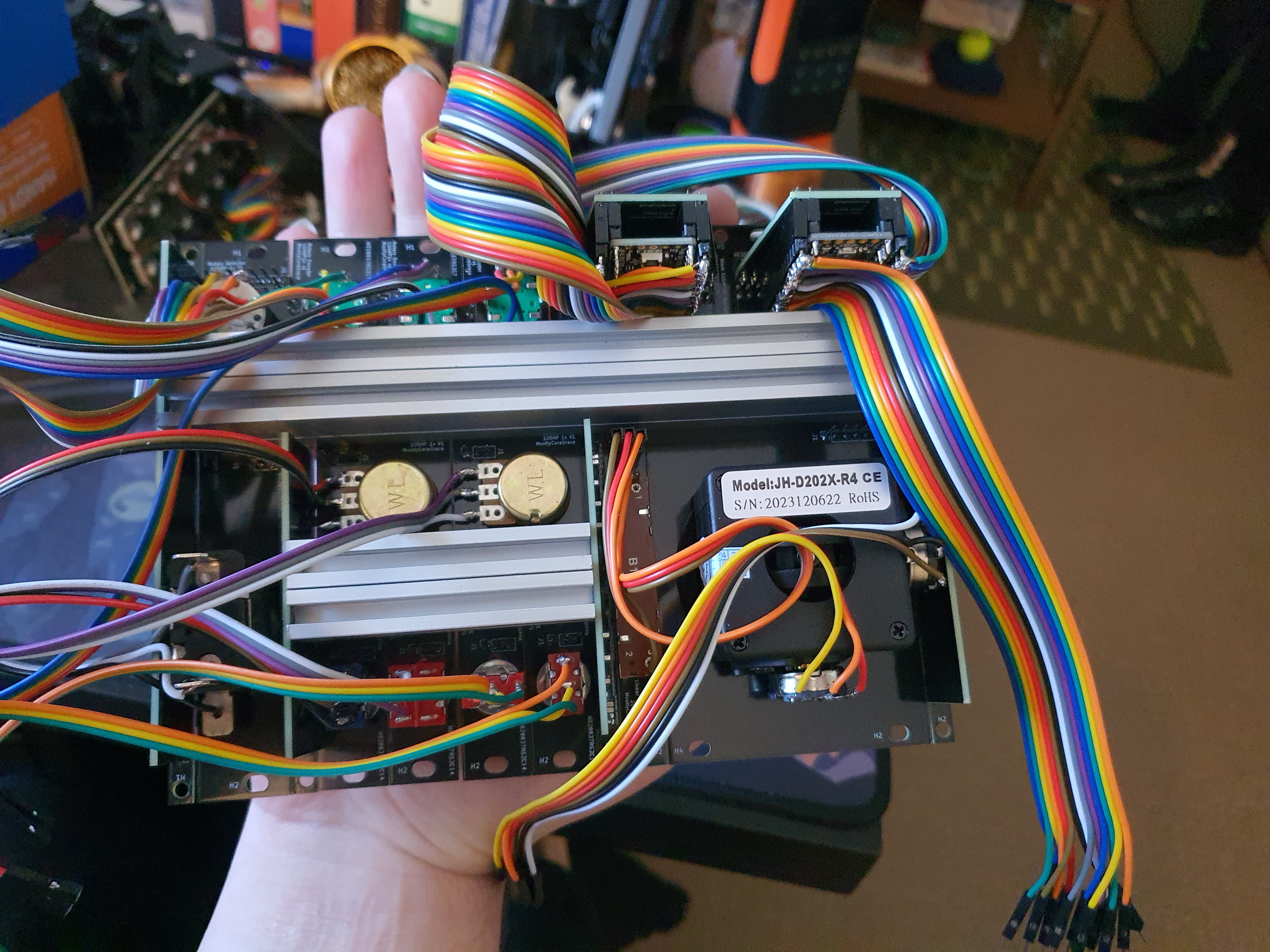
Connecting all the extra wiring together, on a breadboard, was easy enough. It's a *lot* of wires though! so much spaghetti. It did remind me of one thing I had overlooked, which is that many of the components need to be routed to 3.3V or Ground, and if I were to wire this up on the top, I would have no place to wire them up; I hadn't ordered any of the perfboard plates I designed, and I hadn't designed any power or ground buses into the controller board or plates, so I might have to try and shove all these wires into the case anyway!
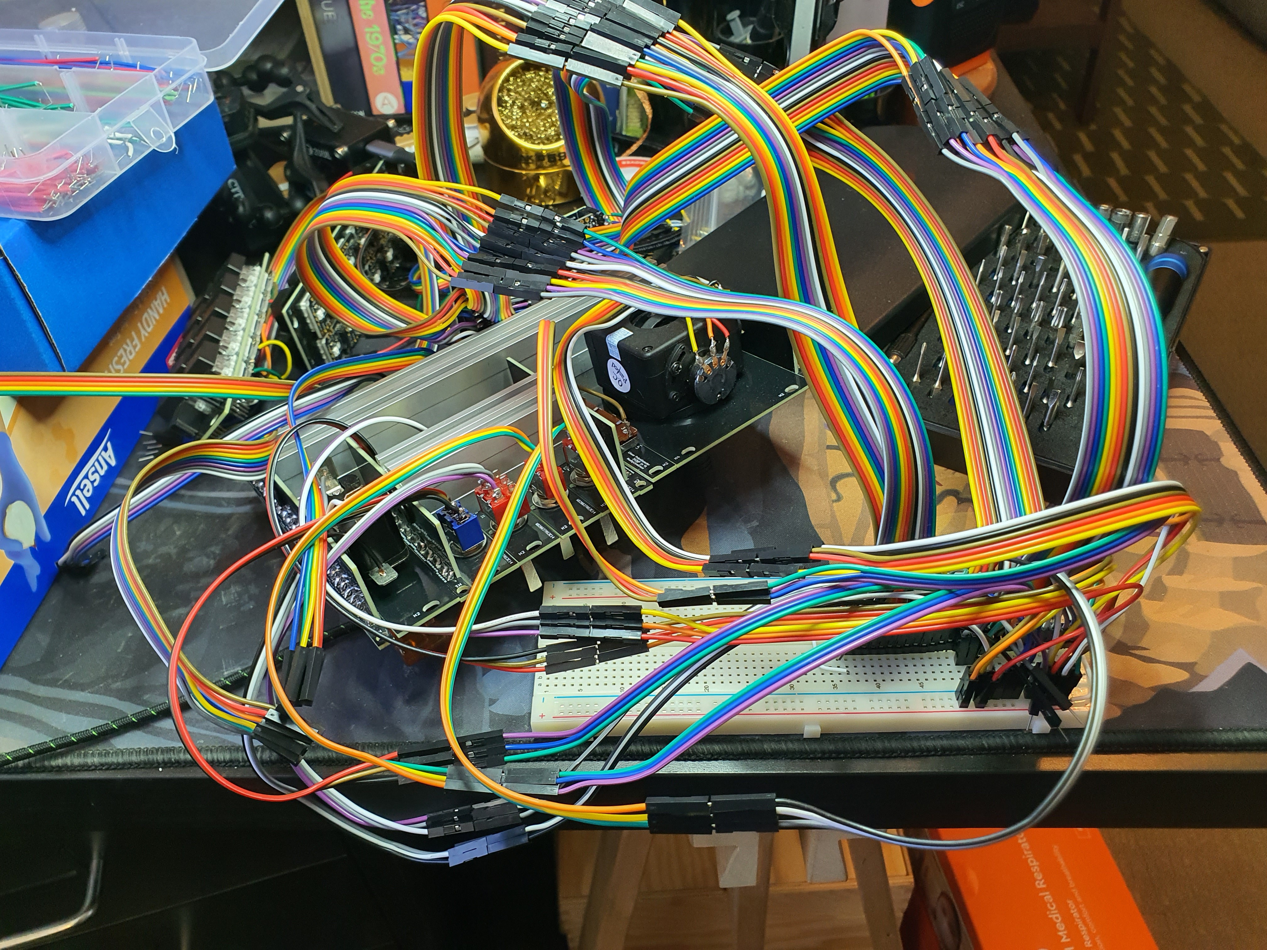
Gotta get those wires grounded somehow, and I'm already half-way towards getting it all inside anyway, so once again I'm thinking farther ahead than I thought, and once again its turning out in my favour! I'm on cloud nine! I'm unstoppable-
ah.
Yeah, that wont work.
A Crossroads
I've got two choices now; go full-ham, hand-solder the wires inside the case, learn how to connect things properly. This is the way I should go, if I want this to be something other people want to have in their house, on their desk. This is the way it *should* be done.
I do not want to do this.
It sounds tedious, complicated, permanent. Difficult.
Scary.
Or: find a way to have a ground and a 3v3 bus on the outside.
I look closely at my breadboard. I've never really paid that much attention to it; just taken it for granted. Now it is providing the one last thing I lack for this to work. I hold it in my hands, turning it over. The front is plain, serviceable. The sides are slightly warped; a sign I cheaped out on these when I ordered them all those years ago. AdaFruit have upgraded the ones they serve on their website now, with a metal base to stop the warping. Maybe I should order some. The back of mine are slightly mushy- there's a sticker here, two-sided tape with some intermediate sponge holding it together. The other side of the tape is untouched, ready and waiting all these years for something to stick to, but why would i-
oh.
I can just stick the breadboard to the back of the case, and-
yeah that'll work.
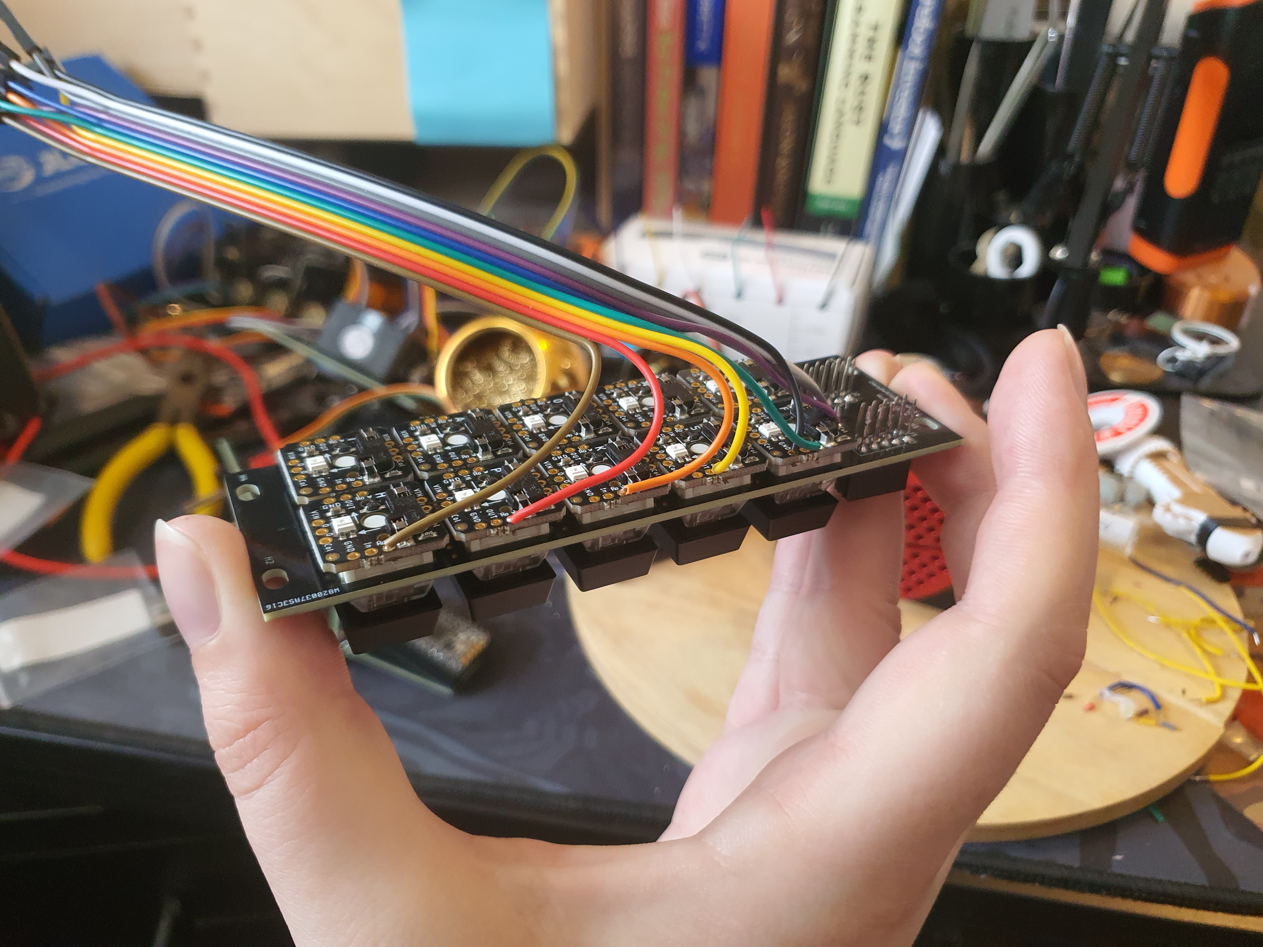
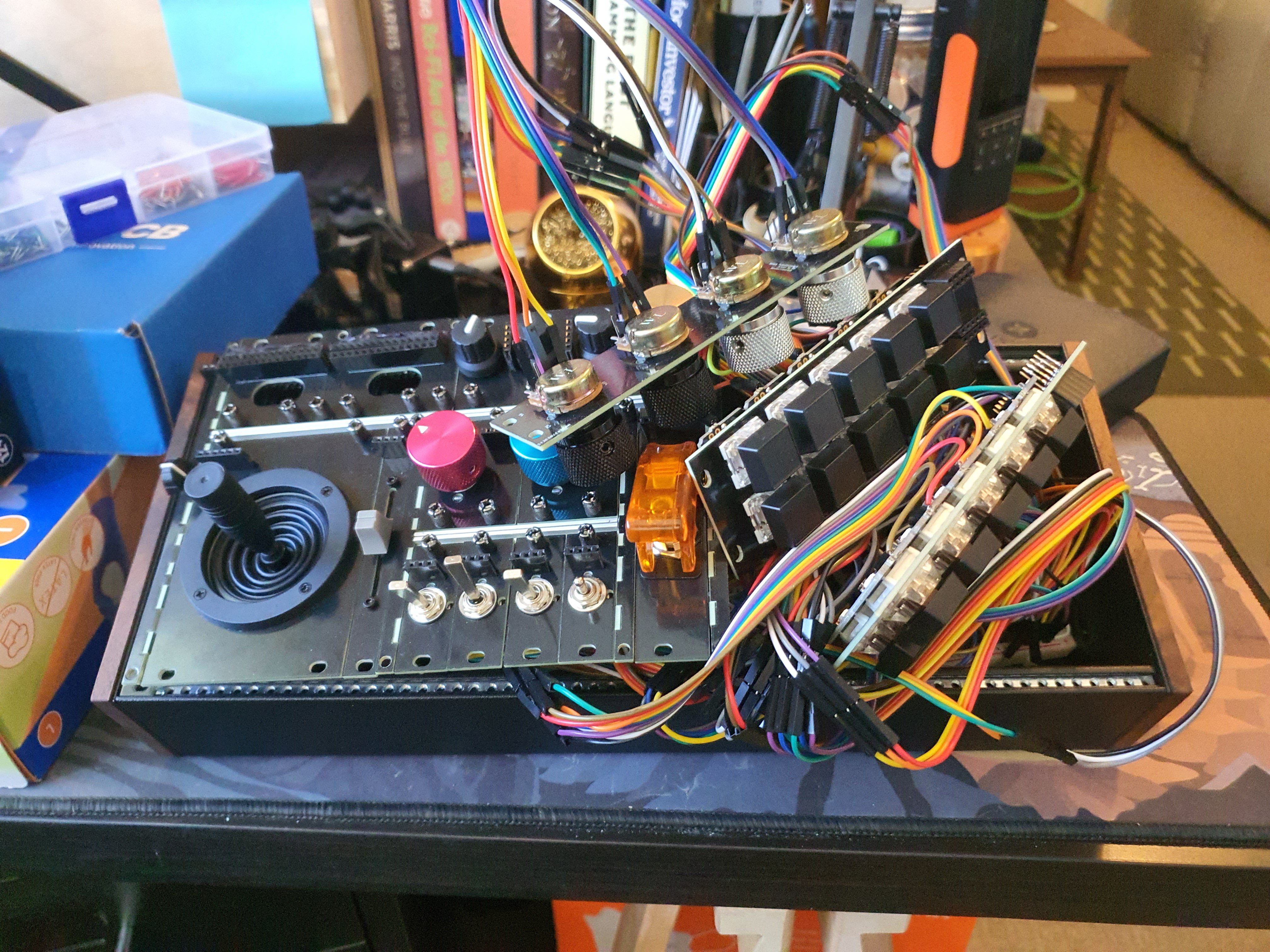
I use some 22AWG wires, colour-coded Red for 3v3 and black for ground, and connect some parts up to the breadboard for my ground and voltage connections.
Yeah that'll work nicely.
This was a fun process; cutting the wires to length, bending and smoothing them Just So to get them to fit along the gaps and spaces between the components. It's meditative, like vacuuming. Do you like vacuuming? I do. The repetition allows for the mind to wander and drift. Maybe you prefer some other activity, like folding the laundry, or washing dishes. Mine's vacuuming.
This Thing All Things Devours
So I finish wiring the thing up. I wrote the firmware as I was assembling it on the breadboard, and it was working then- but it's not working now. I don't know what I did differently. Obviously a lot; the wiring got completely gutted and re-done, but it took me a few weeks! I don't know if I have the constitution to figure it out.
I don't own a voltmeter or whatever they're called; I should own one. How I've made it so far in my endeavours without one is a miracle. But what if I've just fucked it up somehow? Shorted a wire somewhere in the controller; those wires were awful close to the rails.
I sit on it a while.
A week, and then two.
A month.
I have Long Covid. I caught it years ago, but the fatigue haunts me. I can go weeks with nothing wrong, and I feel like I could lift the whole world on my shoulders, like I was never sick, like it's finally left me for good, and then one day I'll wake up and feel like shit. Like I didn't sleep at all. Like I ran a marathon during the night. One such event hit me during this period of limbo for this project. It was not fun. But every day, the Eurorack Button Board would be sitting there, on my desk, waiting. Patiently, like the immutable physical object it is.
Everything decays, but the decay of things like this are on a timescale greater than that of life. It will outlive me. I will be long-gone, but the Eurorack Button Board will still be here, a testament to my aspirations. A monument to my failures and my ambition, my crudeness and my genius.
Sometimes you need to leave a project for a day in order to figure something out. Sleep on it, or take a walk, or read a book.
With Long Covid, that one day away from the project becomes a week, a month. I persevered.
I open KiCAD one day; I think I've figured it out.
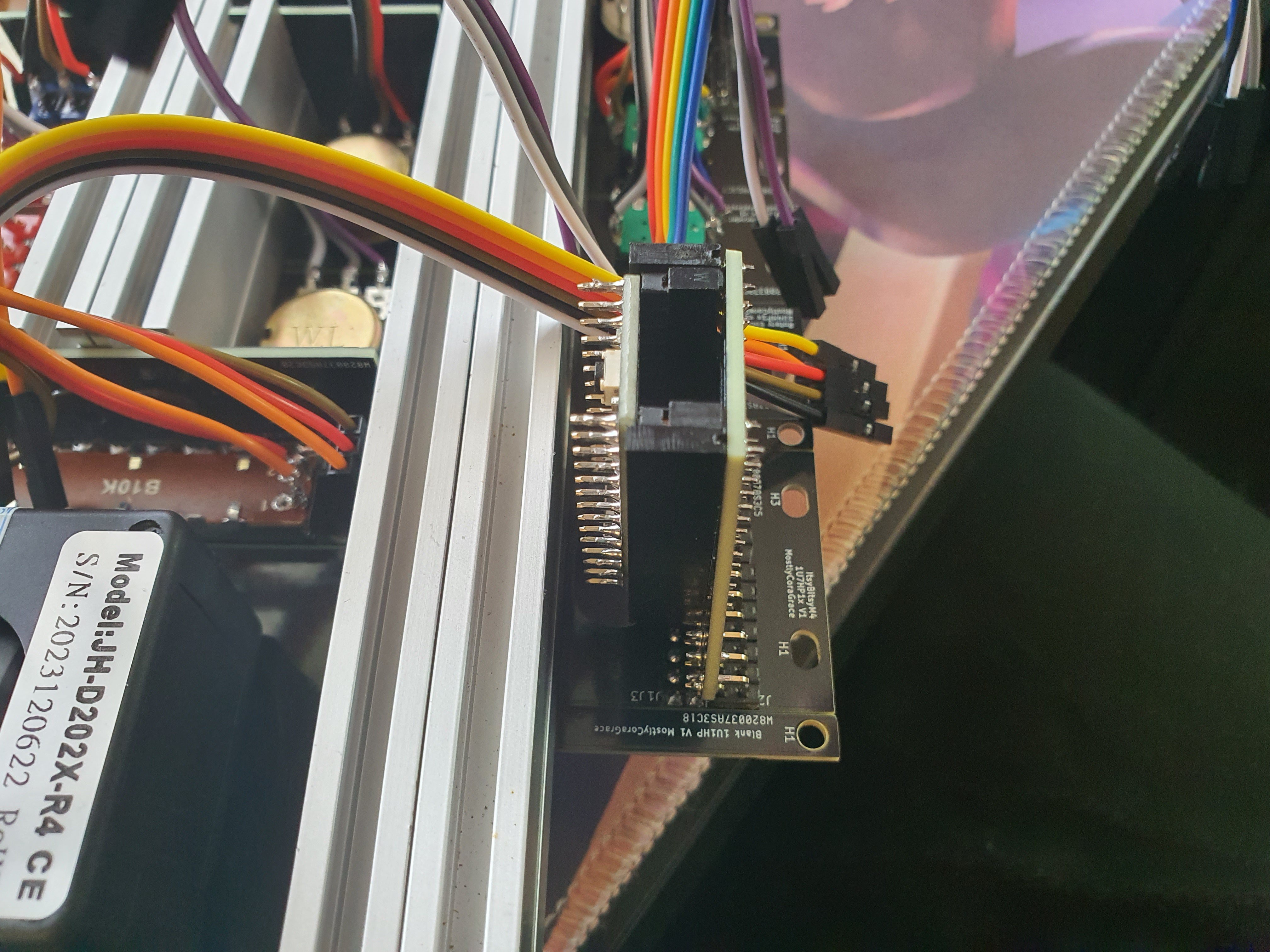
I look closely at the pins of the controller's plate, and vertical mounted PCB. I had originally decided the pins should be somewhat related to the controller they were connected to; imagine the USB port of the controller to be on the left of the headers; the bottom row of headers on the plate would be the left row of headers on the controller, and so with the right. But in my excitement in the sponsorship, I rushed things; I got ahead of myself. I messed up.
I look at one pin on the PCB design in KiCAD, and its corresponding header on the plate is on the left; this is correct. I look at the other pin on the other side of the controller, and its corresponding header on the plate is on the other side! It's flipped horizontally. Oh no!
I had tried all other combinations; what if the headers were both flipped horizontally, what if the headers were flipped vertically; the left one on top, and the right one on the bottom. No; The left one was correctly on the bottom, but the right one was flipped horizontally on the top!
Of course, this wasn't a problem when I was testing things on the breadboard, since I was connecting directly to the side of the controller via the headers directly next to their corresponding controller pin.
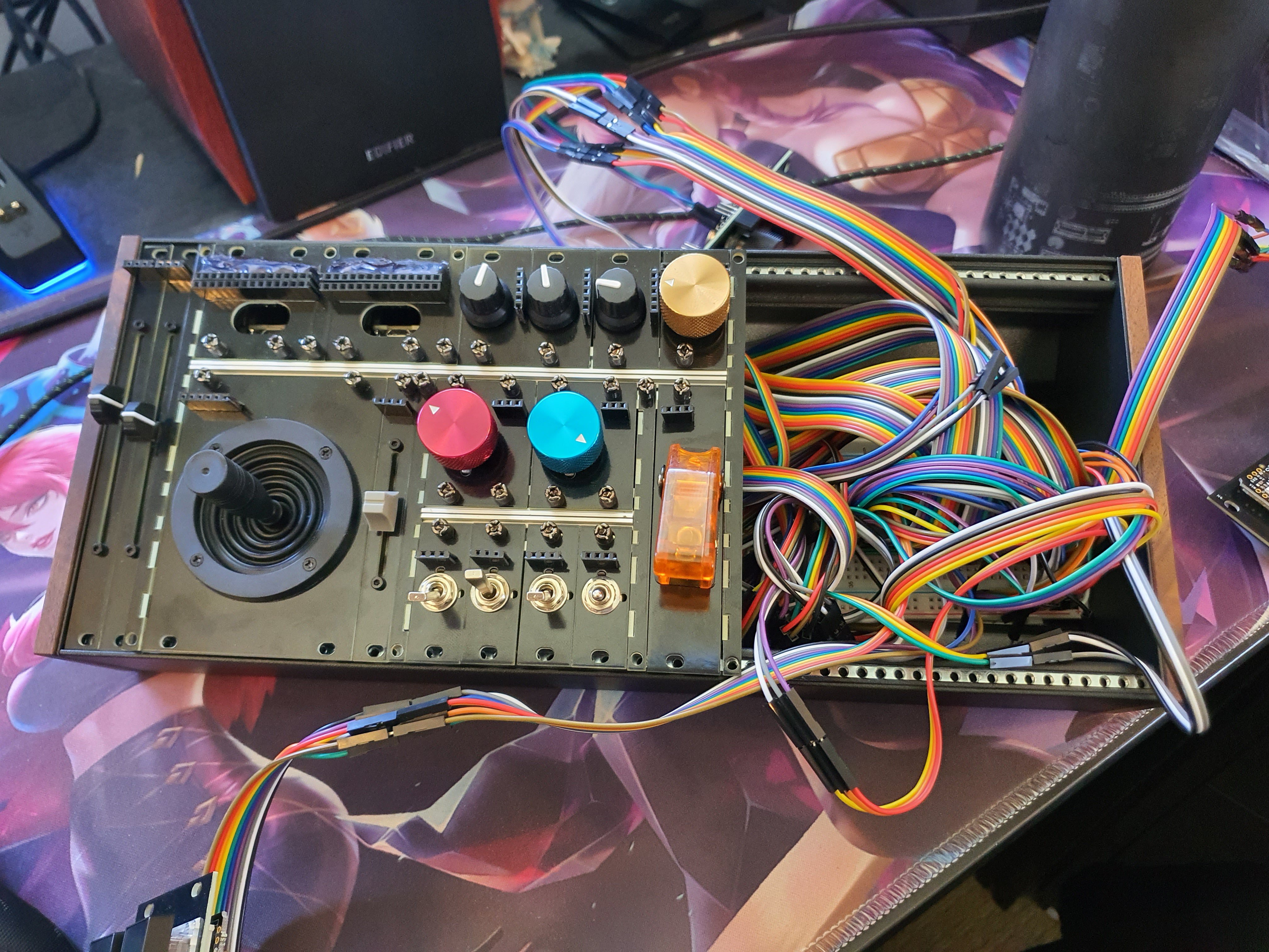
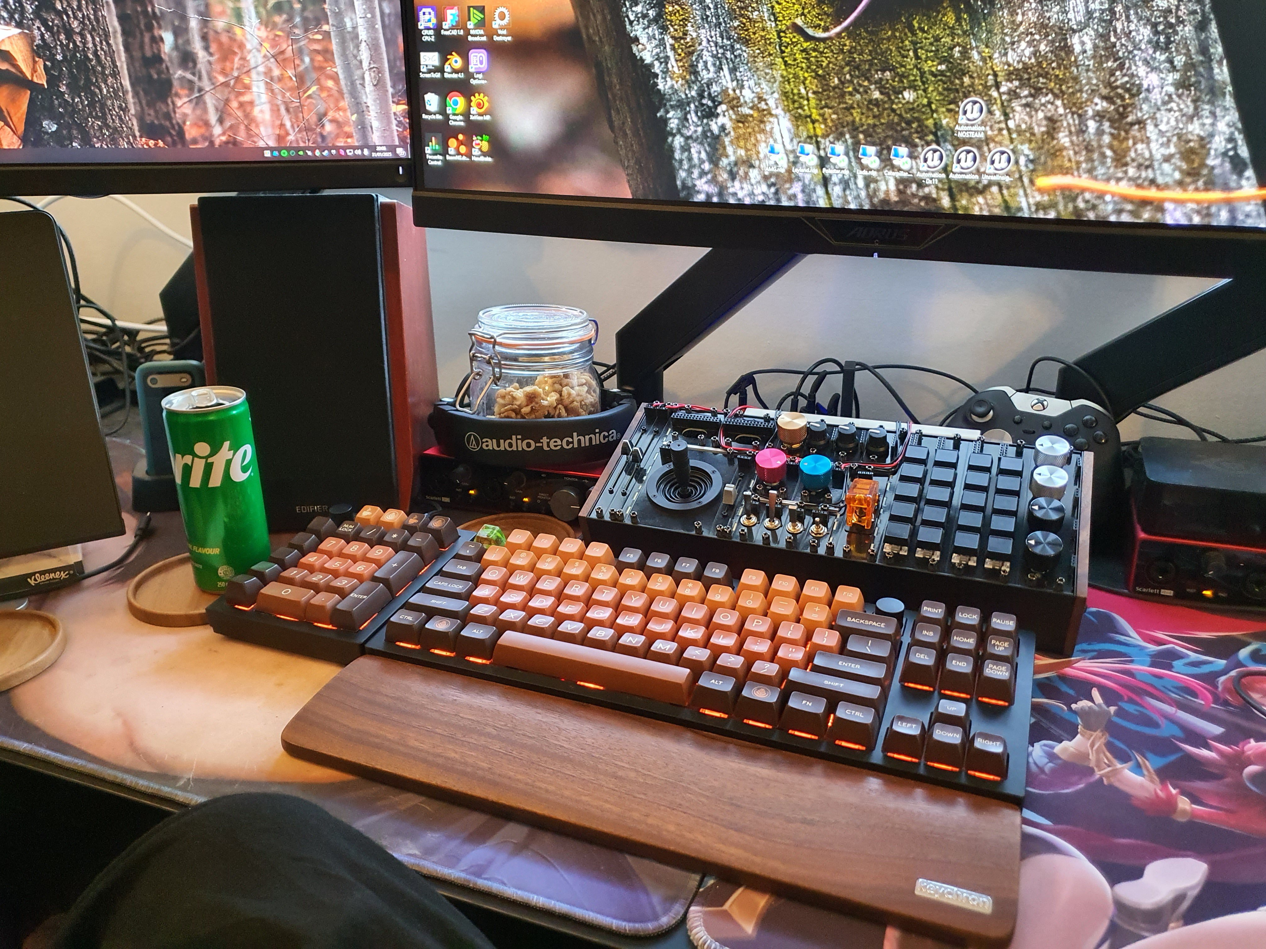
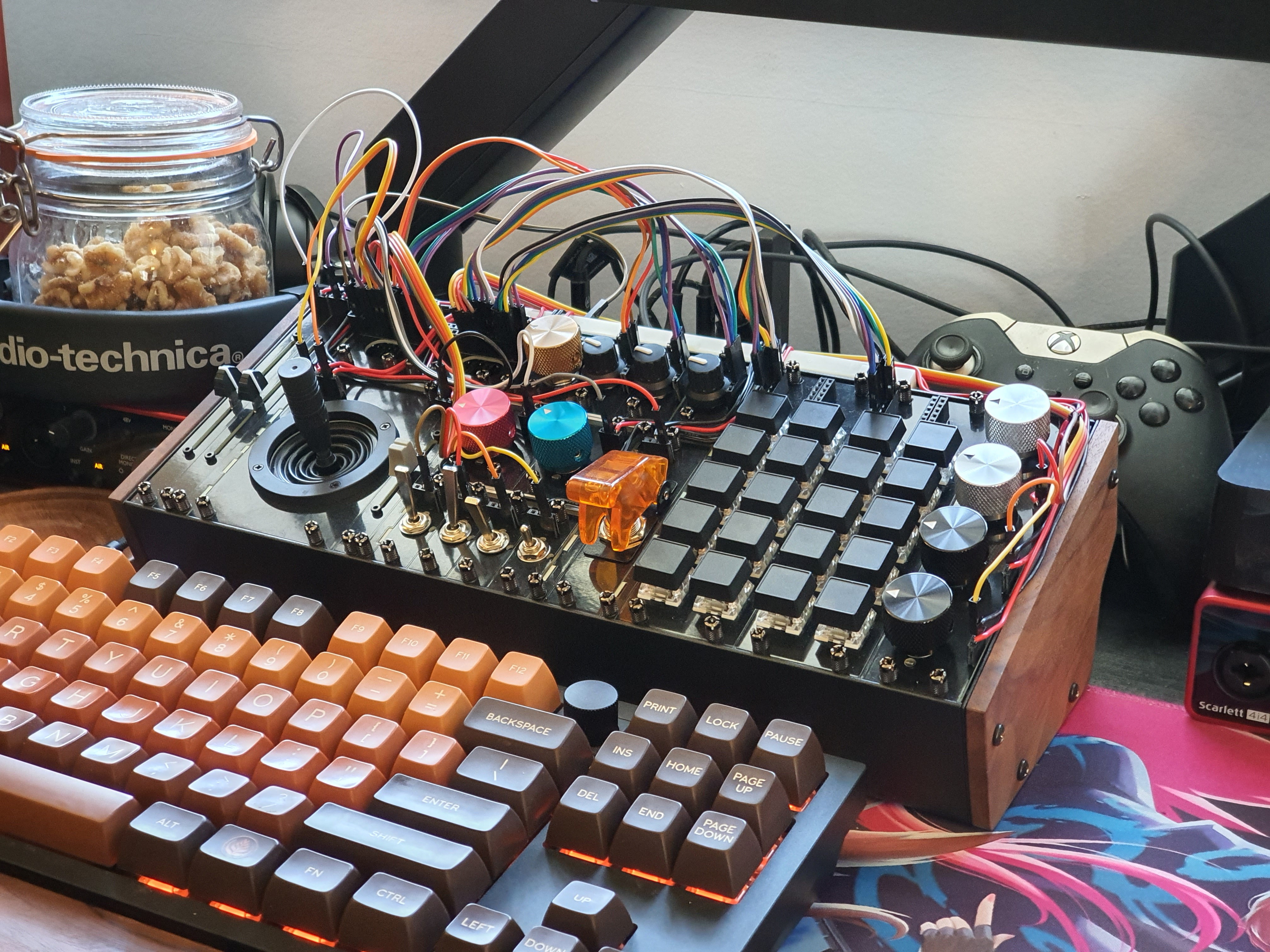
I re-wire things up; One button works. I wire a slider up, it works too. I wire the knobs, the keyboard matrices, the toggle switches, the rotary encoders. They work.
I launch a game- I bind the buttons, and the knobs, and the sliders; it works. I've done it.
Tomorrow (for realsies) I will take some final pictures and finish up the documentation. For now, my ADHD meds have run out, and I need to sleep.
Discussions
Become a Hackaday.io Member
Create an account to leave a comment. Already have an account? Log In.