 Cora
CoraFinding the parts to use, and making sure those parts fit witin the Eurorack standard was a fun and interesting challenge.
Following the Eurorack sizing guides from Doepfer and Intellijel, I could tell that I have only a certain amount of space in each module, if I want to be able to use a normal Eurorack case to keep it all in once it's done.
Some parts, like this Motorized Slide Potentiometer would be quite fun, but sadly are too long for a standard 3U module; I would have to find (or make) a case that was 4U in height. I didn't want to go quite that far for this project.
Other parts, like this smaller 75mm Slide Potentiometer fit just fine in 3U.
Some other parts would fit in 3U, but there would be a lot of wasted space around them, like this Mini Analog Joystick.
Perhaps if I smudge the Eurorack format a little bit? keep 3U and 1U modules, but also have modules that would fit into 2U? I mean, if I'm putting 1U modules into a 3U case, I'm going to have 2U left over... and sure I could fill that with two more 1U modules, but why not just have some 2U modules? That could be fun!
I'm not here for an Artisinal Experience
I'd previously ordered some PCBs from several places for other projects, and knew intuitively that what I was after for this project could easily be made and shipped to me for cheap as PCBs, and would quite easily fit the bill of requirements for an Eurorack module. by buying a Eurorack case, and filling it with PCBs-as-plates for the modules, and mounting the Electrical components directly to them, I could get away with a minimal amount of manual labour. All I would need do is solder it all together, and I wouldn't need to faff about with a custom 3D-printed-anything, or manually drilling holes, or any of that fun stuff. Just made-to-order goodness.
The Fun Part
I created some crude approximations of some components I found online (mostly AdaFruit, and AliExpress), and imported them into Blender. These will be my playing blocks.
I then designed some rough outlines of the Eurorack rails.
Making frequent comparisons to the sizes of the front face of the modules on the Doepfer website, and the sizes of the PCB on the Intellijel website, I could ensure that whatever component I designed around would fit in the spaces I wanted to put it.
I played around with positioning and sizing of the components, I came up with several sizes of module that fit each of the parts I wanted to use. This is what they look like:

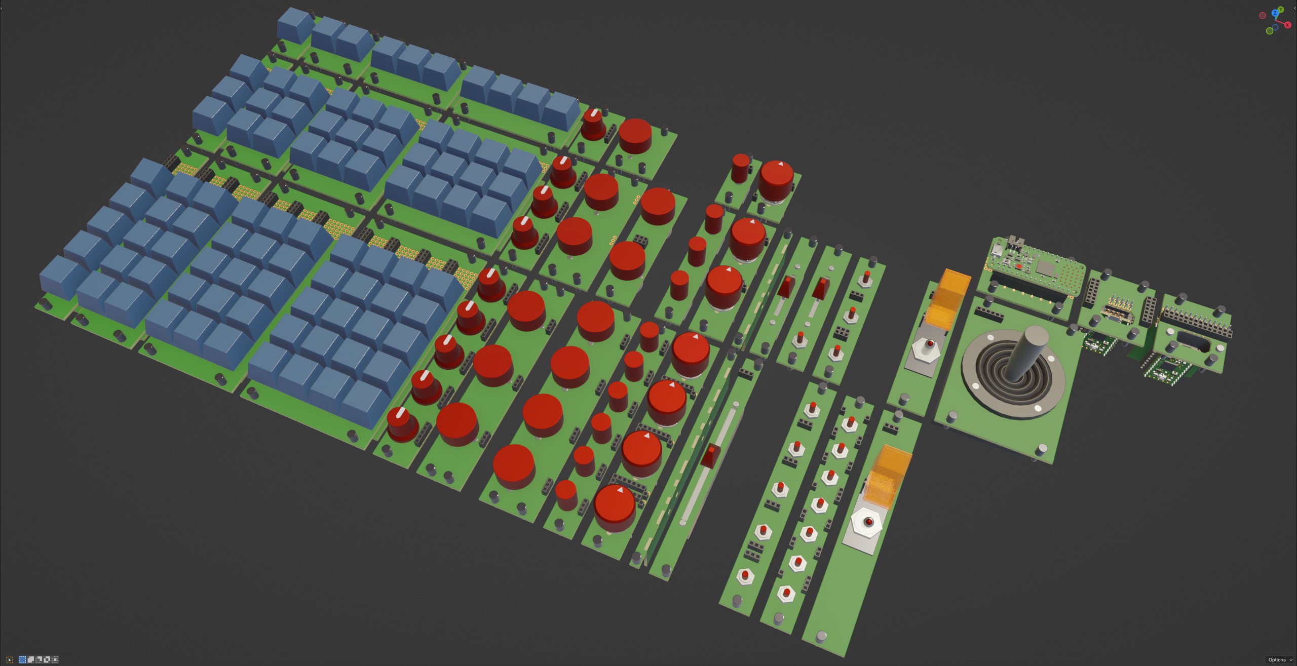
Since I'll be wiring this all up by hand, I only really have to worry about whether there will be enough finger space between each component once it's all assembled. So long as the part fits, I can add more blank spacers between the parts if I find it's all too cramped.
Discussions
Become a Hackaday.io Member
Create an account to leave a comment. Already have an account? Log In.