 Cora
CoraOnce all the components spent their time in transit and were all collected on my workbench, I decided the first order of business was to dry-fit everything together; it wouldn't do if any of the parts I ordered were off or mis-sized, either by fault of my own design or otherwise!
First up, the plates:
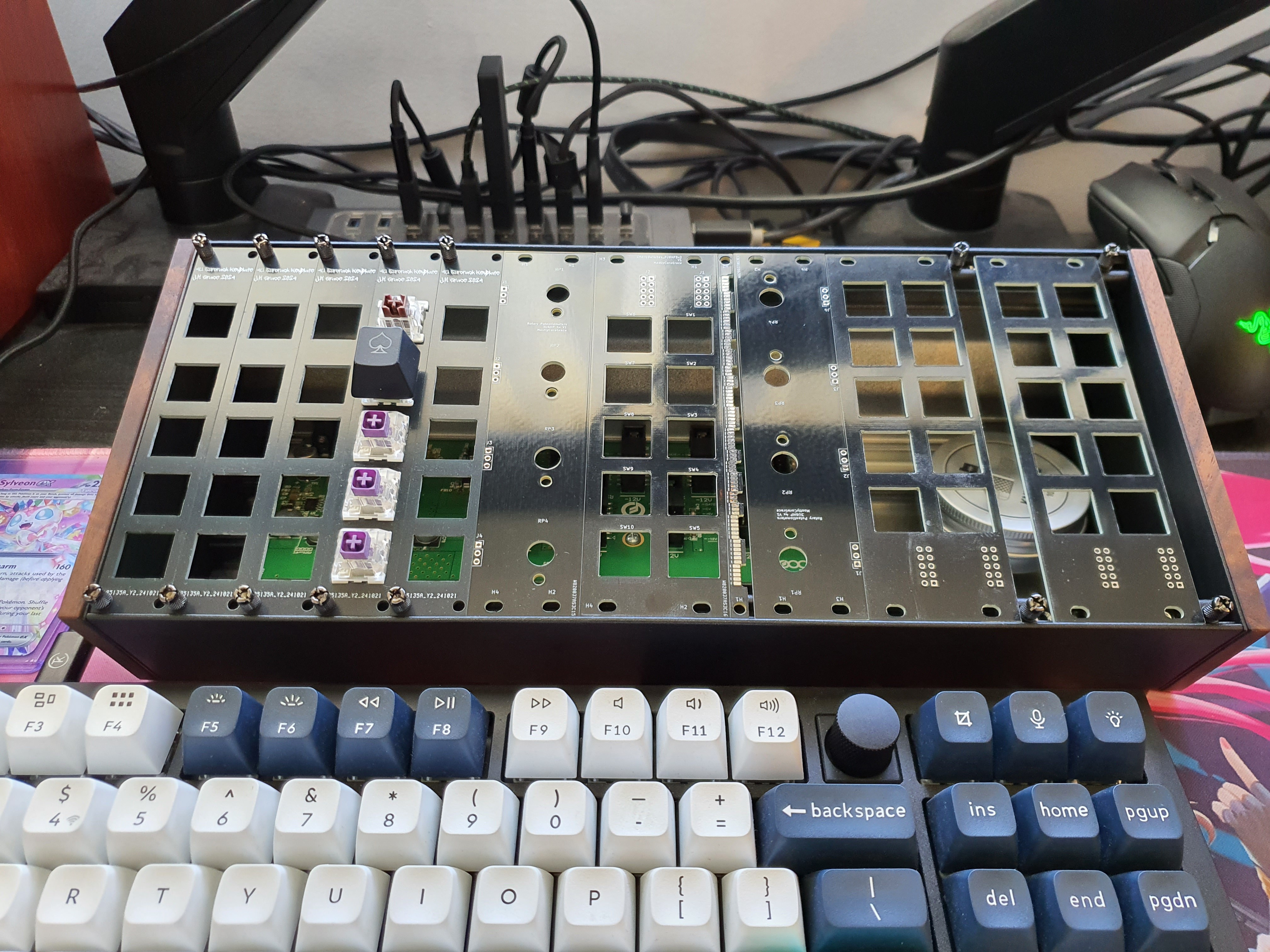
so far so good!
The next part is where it gets tricky.
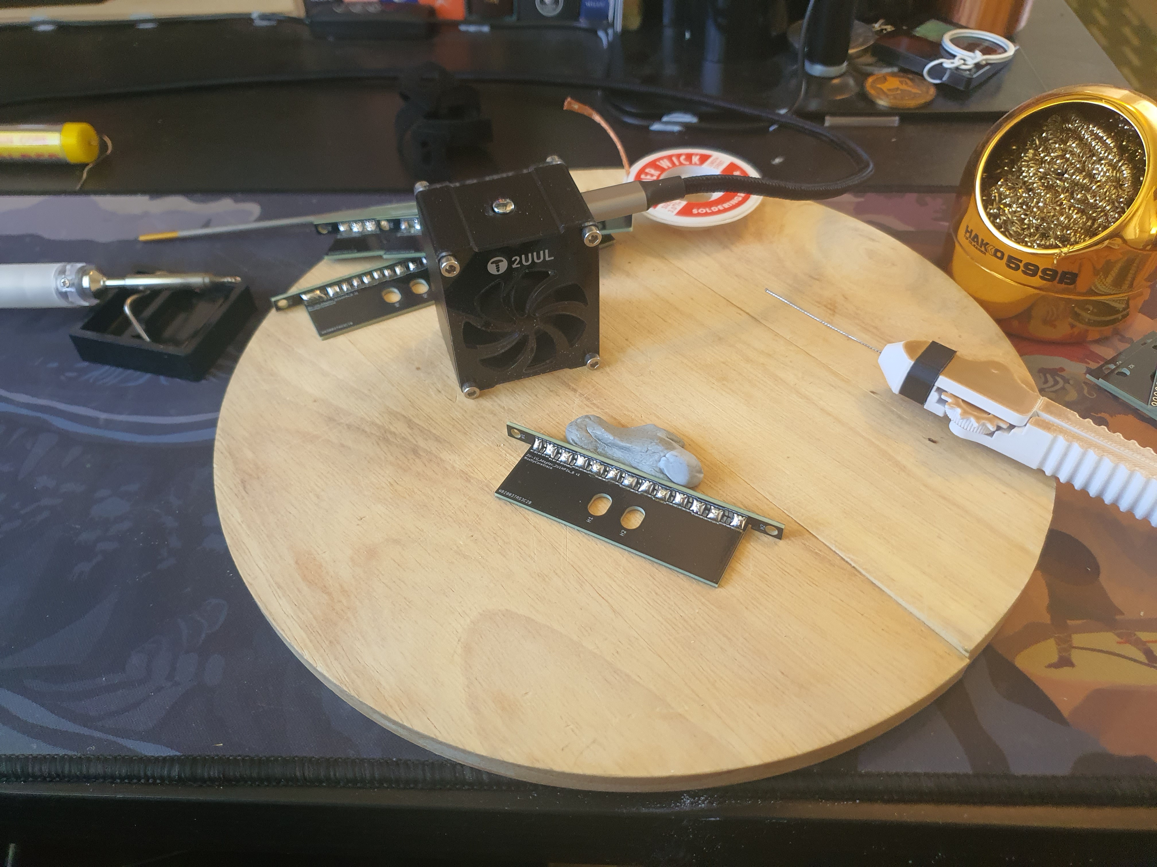
In order to dry-fit the more interesting 1U and 2U parts, I'm going to need to assemble the adapters I designed. The screws for them haven't arrived yet, but I ordered some other not-quite-as-nice ones from my local hardware store, and they will do for now.
I designed each of the parts such that they would be quite tight, but even so I did need to take a small file to them to get them to fully fit together. If I were to re-design them, I would add areas into the inner corners of each of the fingers to make sure the mill didn't leave too much material in between them. Thankfully, they didn't need much filing, and after a few attempts, they went together nicely.
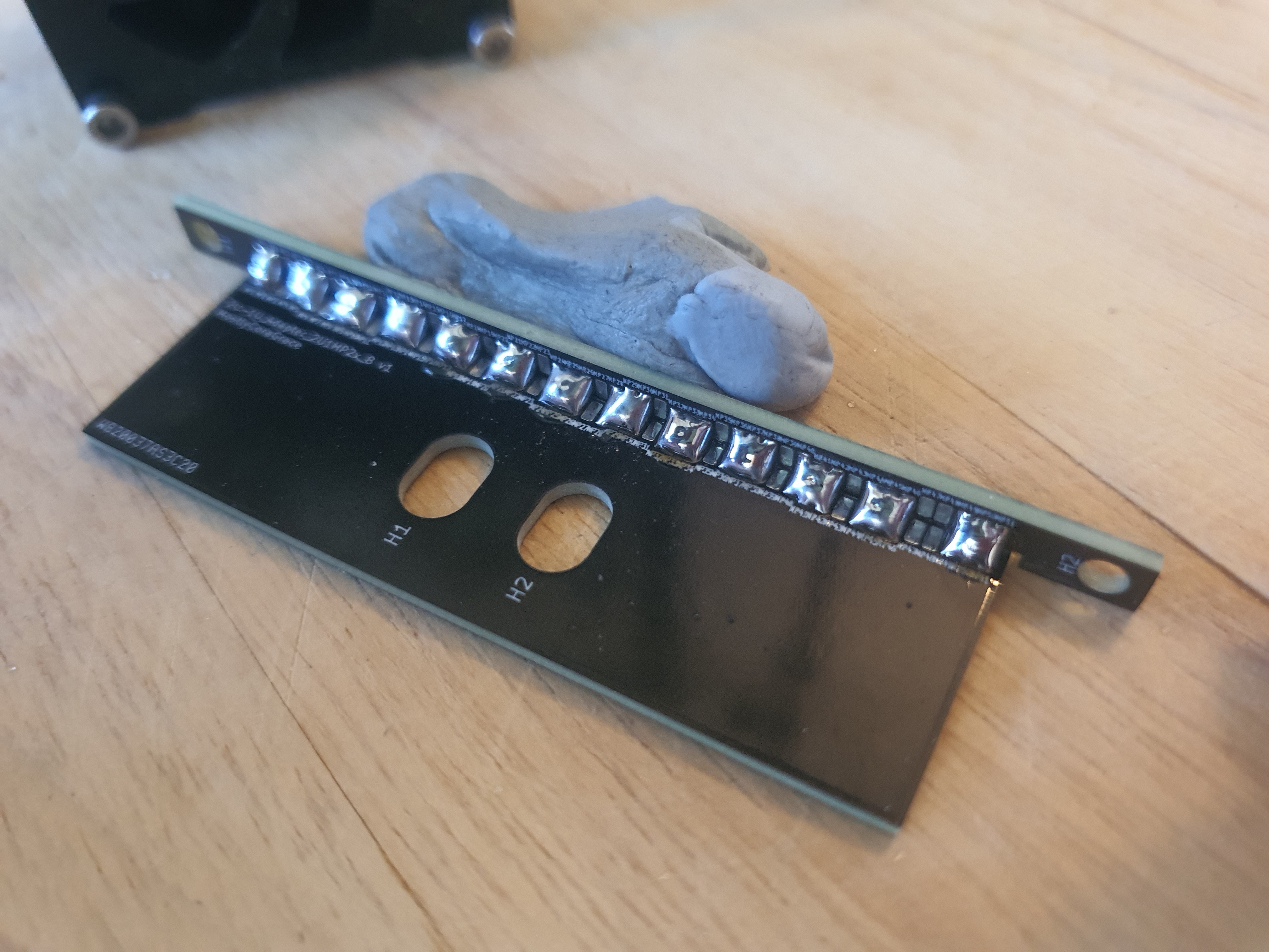
Lining the two parts up with some blu-tac to hold it all together while I work, I first soldered just one corner on, then the other, and when I was happy with the angle I finished the middle sections.
PCBs have a bit of slack in them, and I took advantage of that as I worked the corners. I could finish one corner, check the angle of the plates, and bend the other corner into shape while the solder was hot, then simply re-heat the opposite corner to release the stress.
I designed many separate PCB-Attachment sections into the design because I wasn't sure if one single large slot would work, in terms of being able to heat it all up with my soldering iron while the solder melted into place, but I also kept in mind that the very tiny (1.25mm) slots might be too small to bother doing individually. I played around with a few combinations until I found one that worked nicely for me, which ended up being sets of 3 soldered together with one set between each. This was much easier to solder, and not too finicky to deal with.
Lining them up on the table once they were done, I could get the screws tightened on the rails and make sure they were tried and true. The PCBs were nice and strong, and the rails light, so they didn't need much tightening, and all in all it was fairly painless!
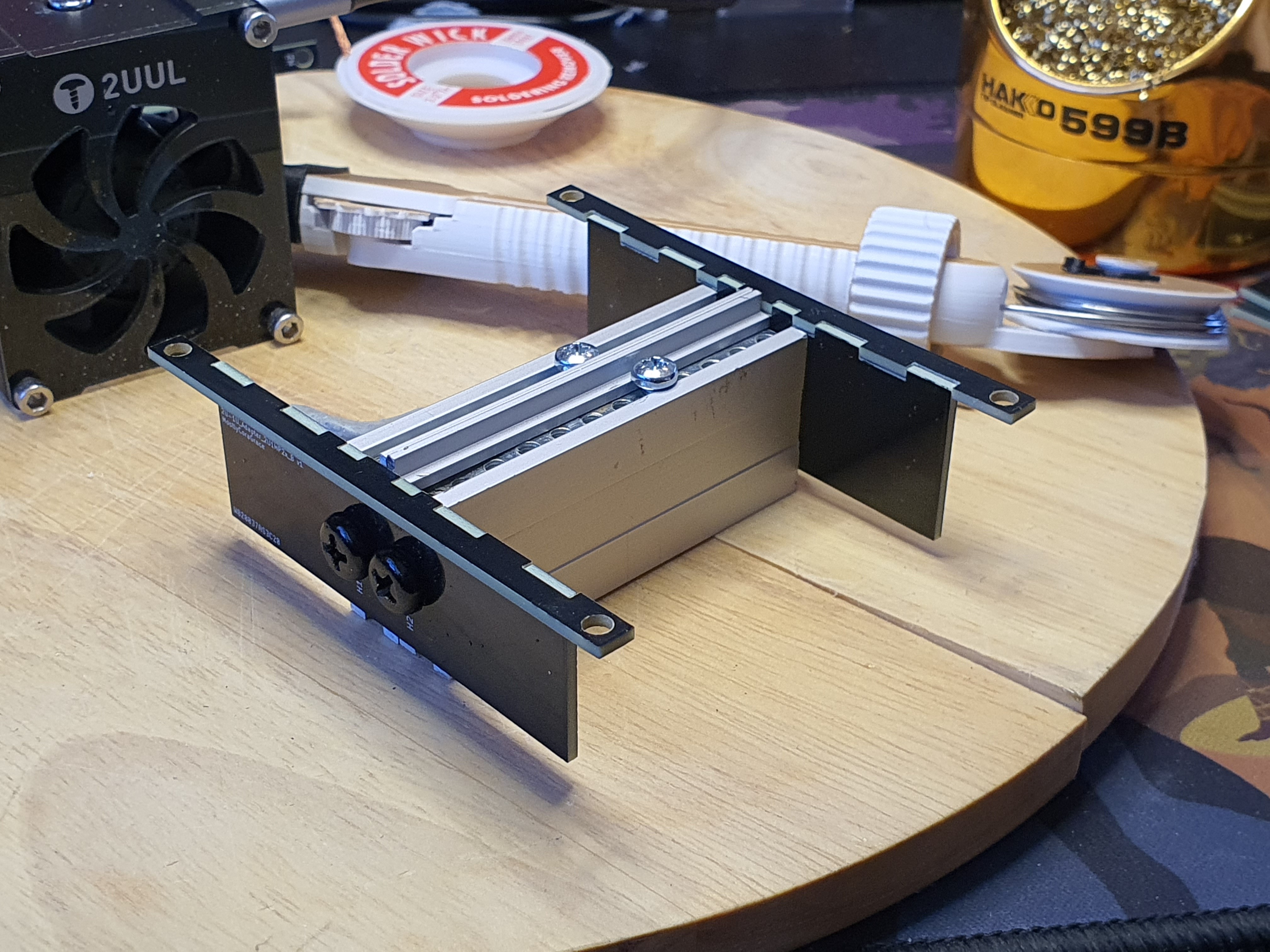
I then put the rails into the case, and made sure they fit, and.. oh that's really quite nice, isn't it?
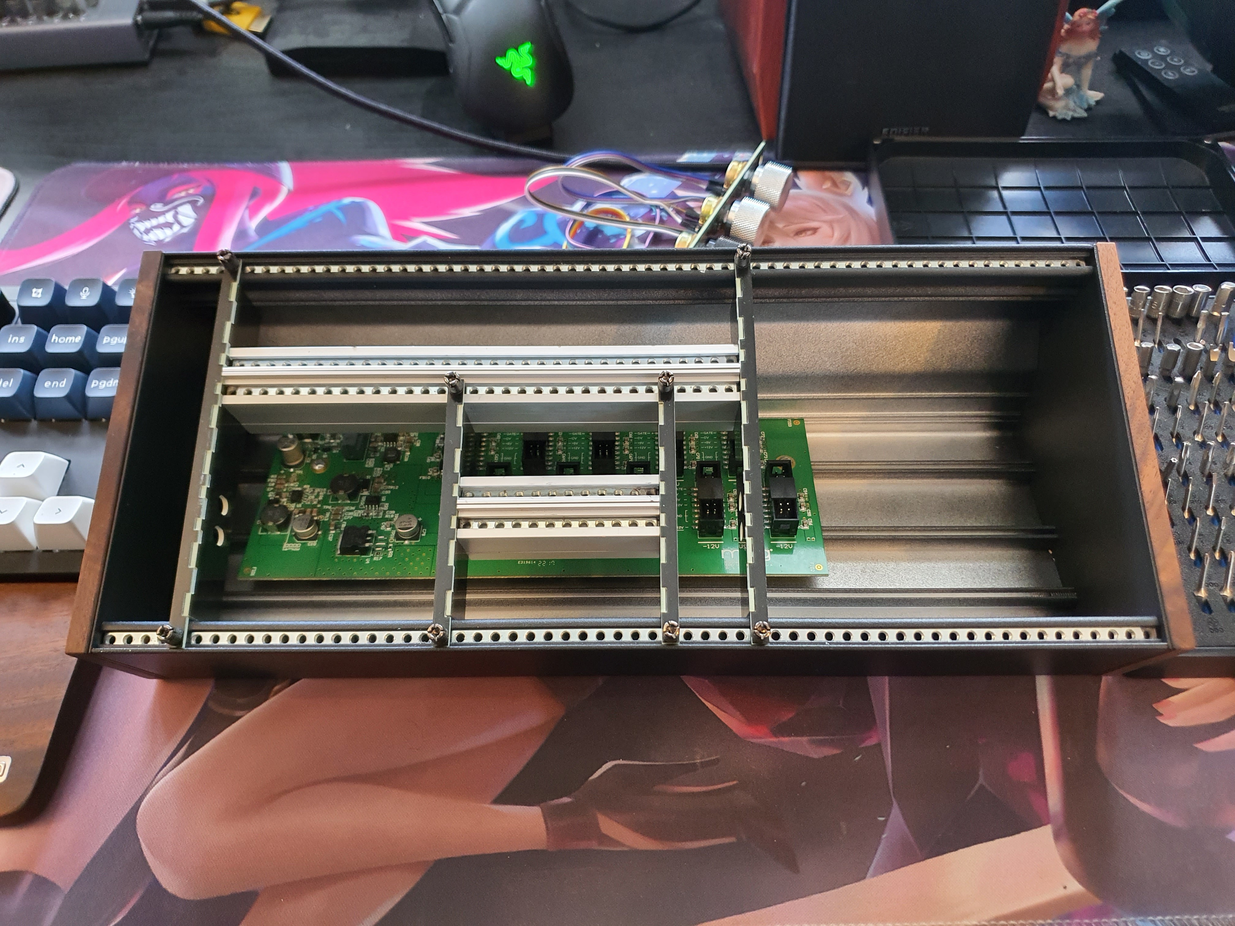
Maybe I will mention this in the Eurorack community, I'm sure someone would love a nice homemade alternative to some of the 3U-to-1U adapters, especially one as flexible as this! Just order the lengths you want, and solder it, and it's done! Perhaps I will do this alongside the publishing of this log update.
Anyway, now that I have the rail adapters done, I can screw in each of the individual electrical components into their respective PCB plates, and this is what that looks like:
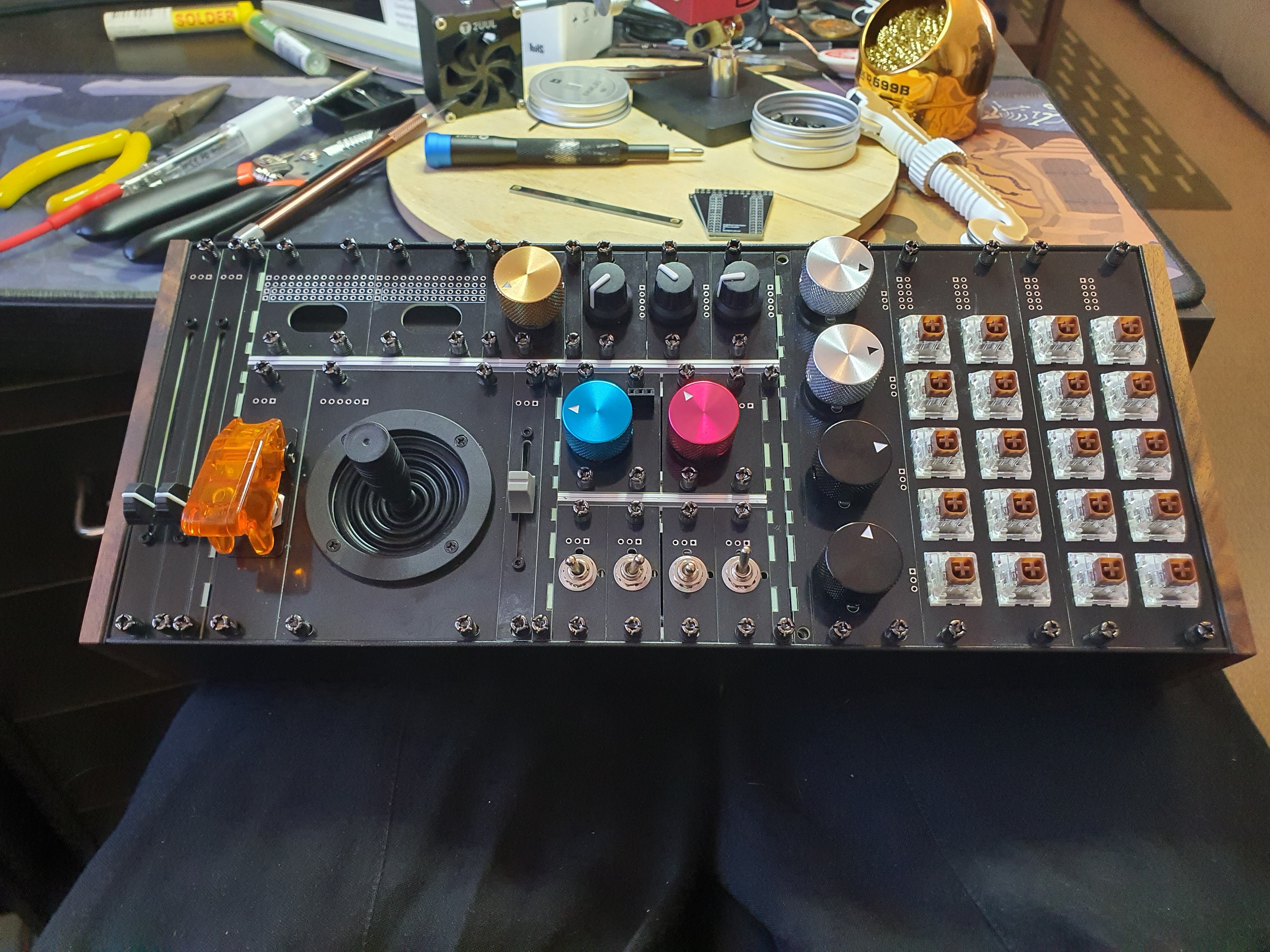
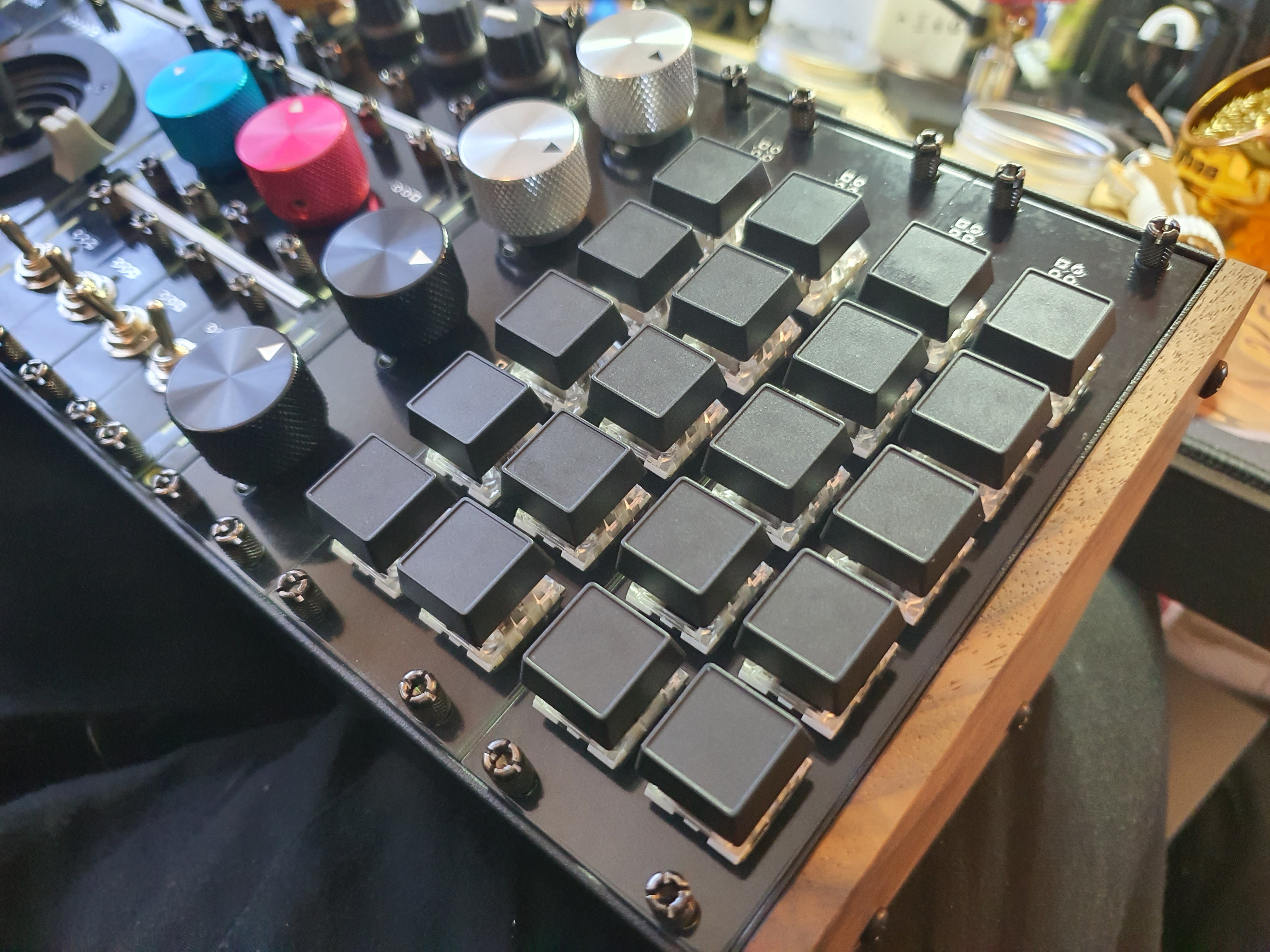
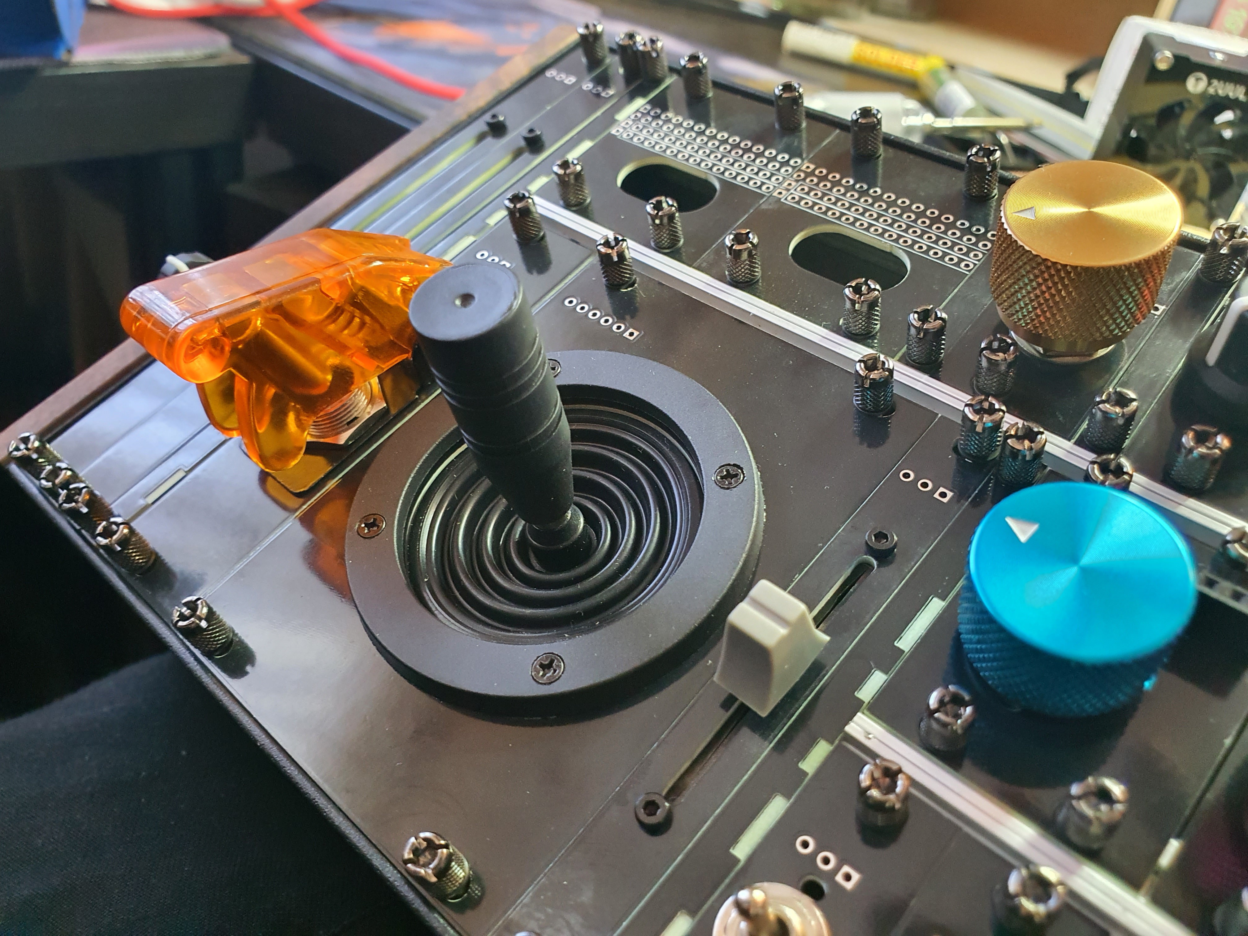
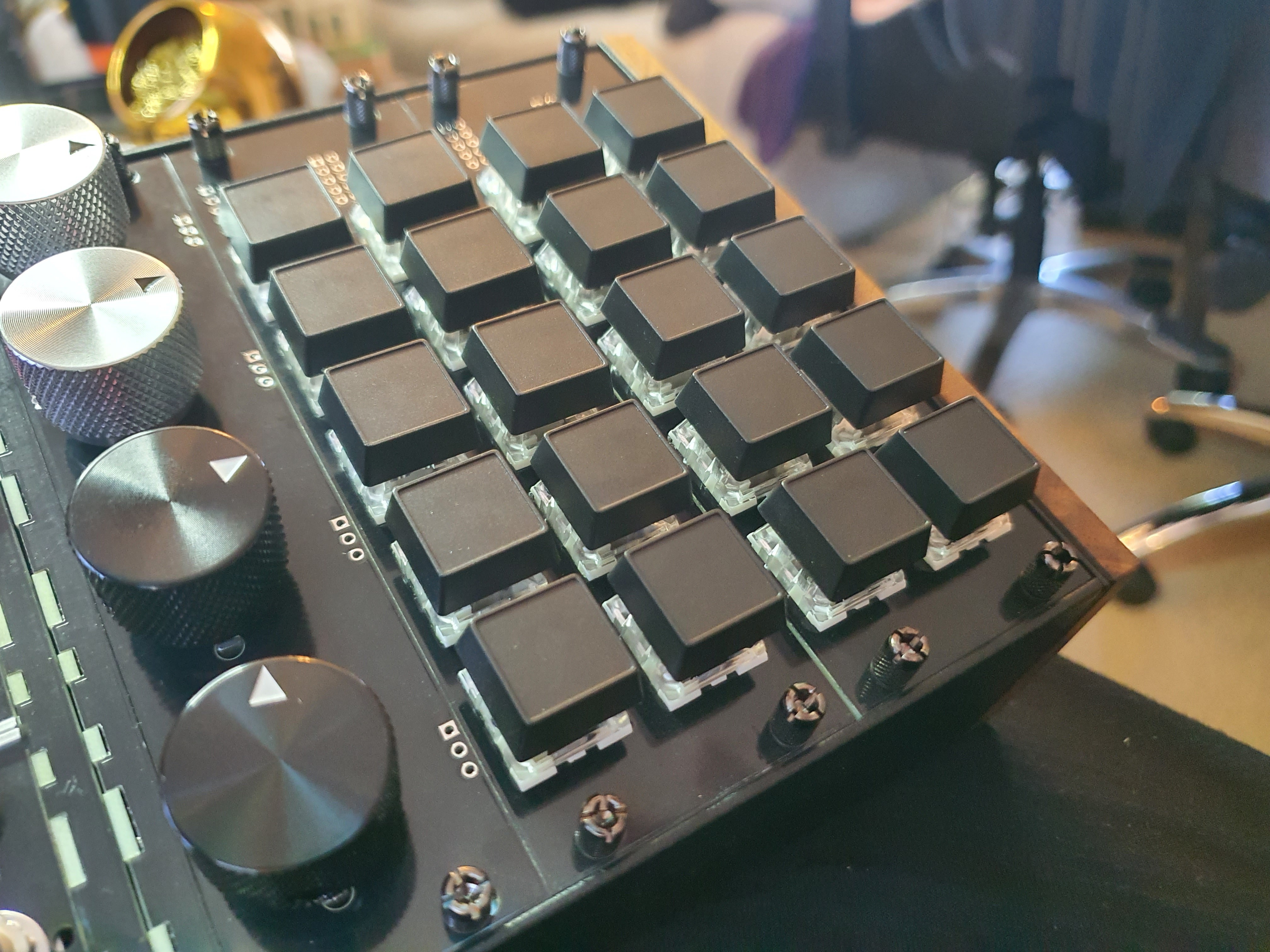
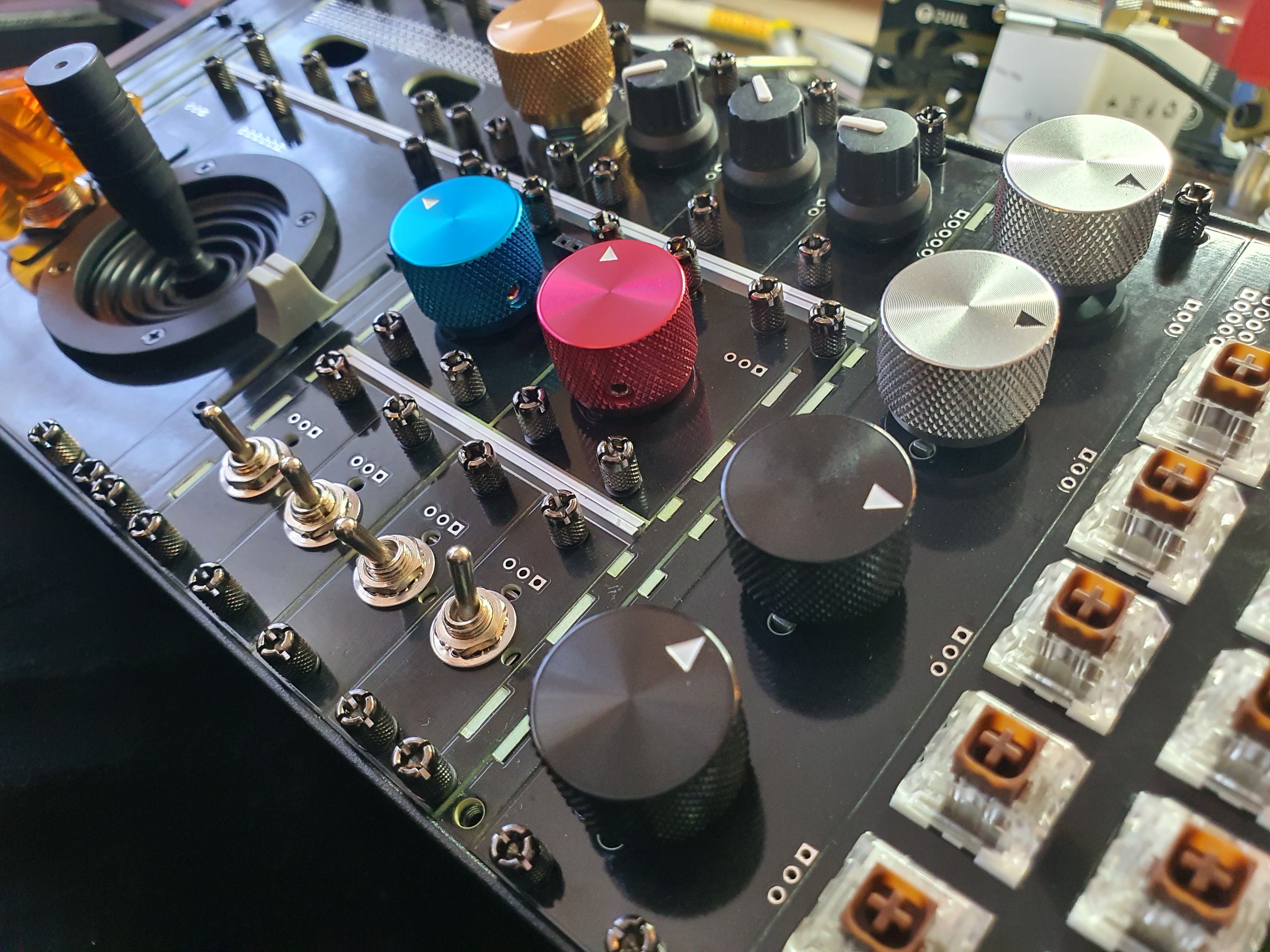
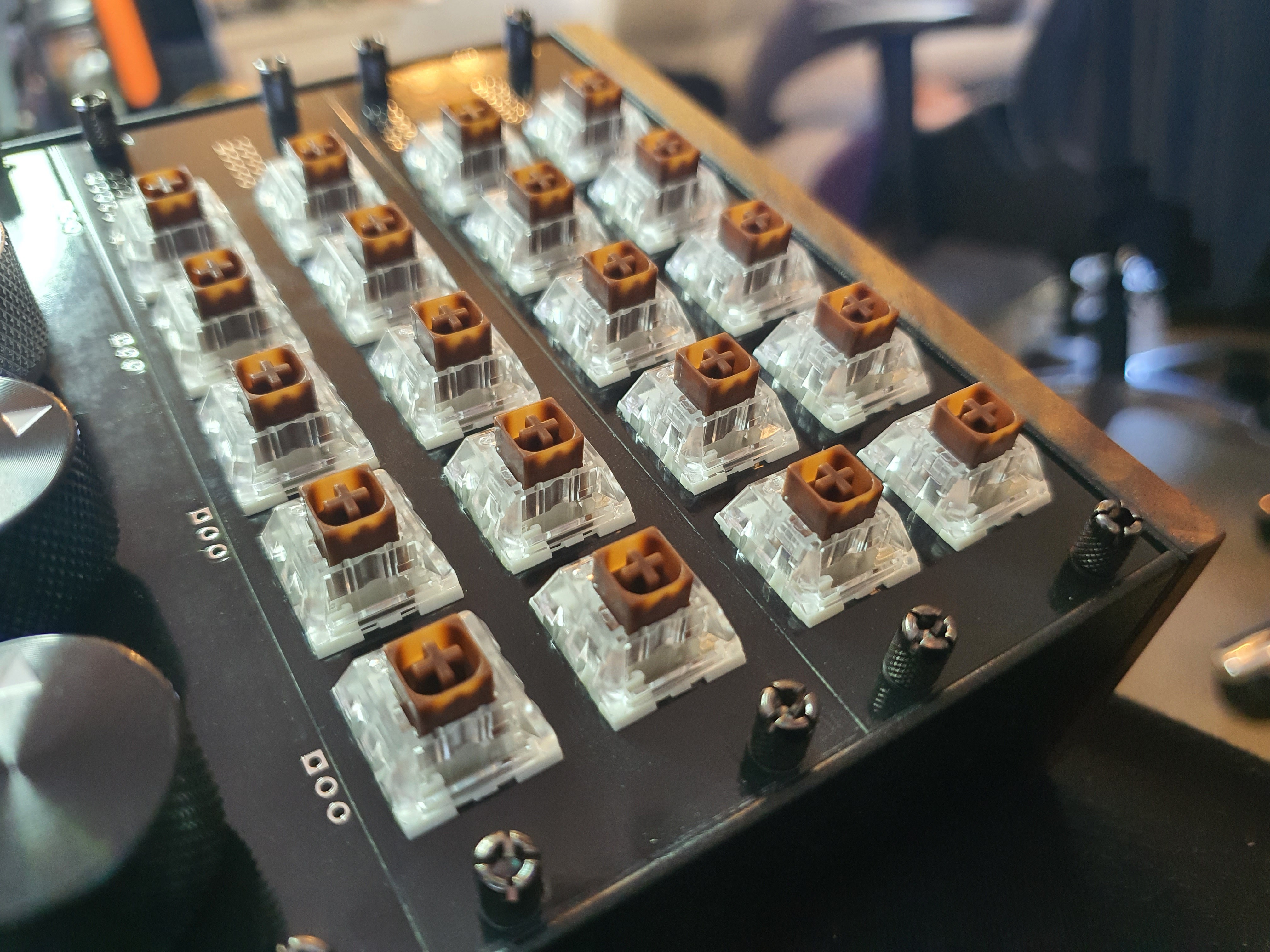
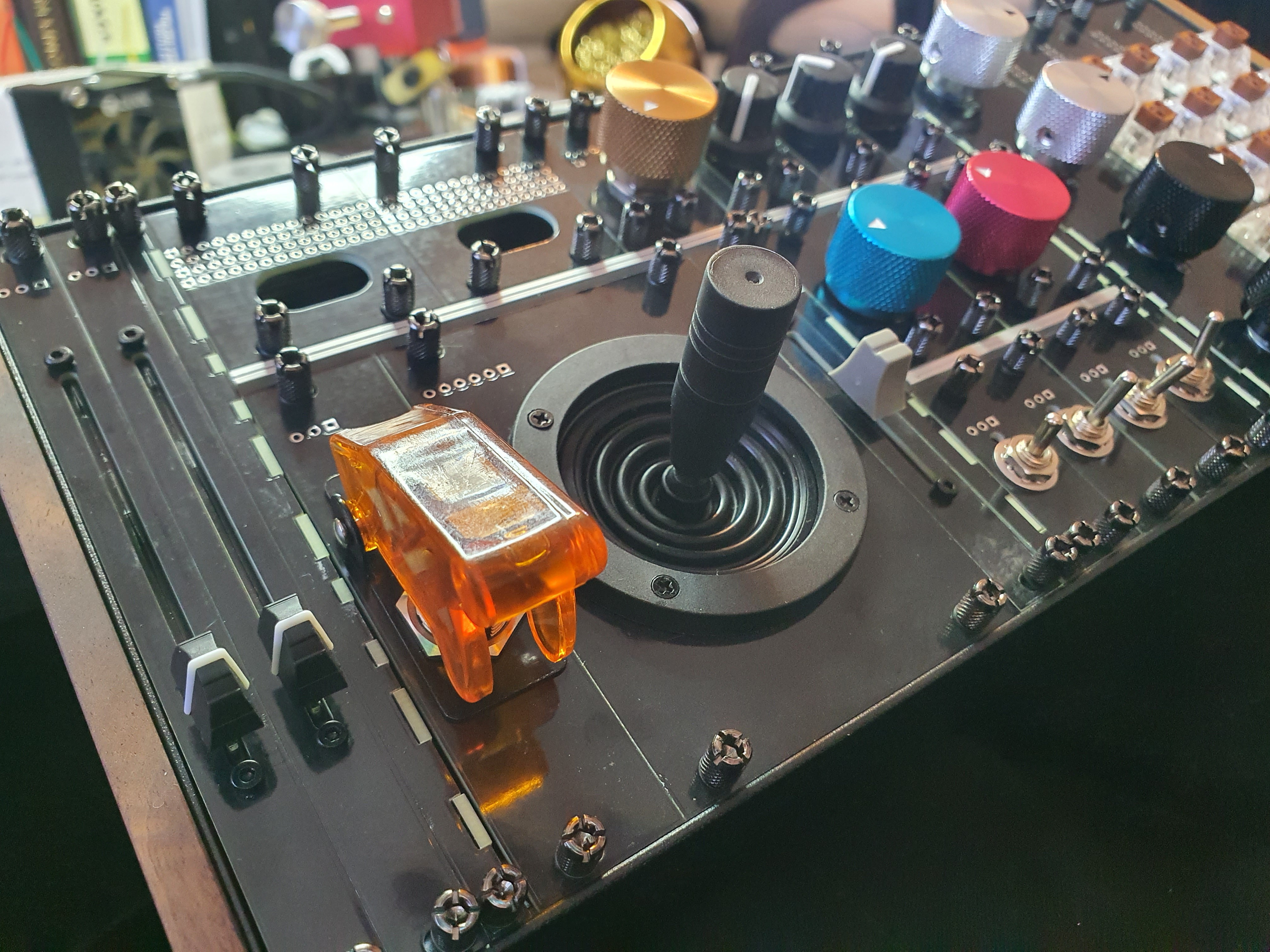
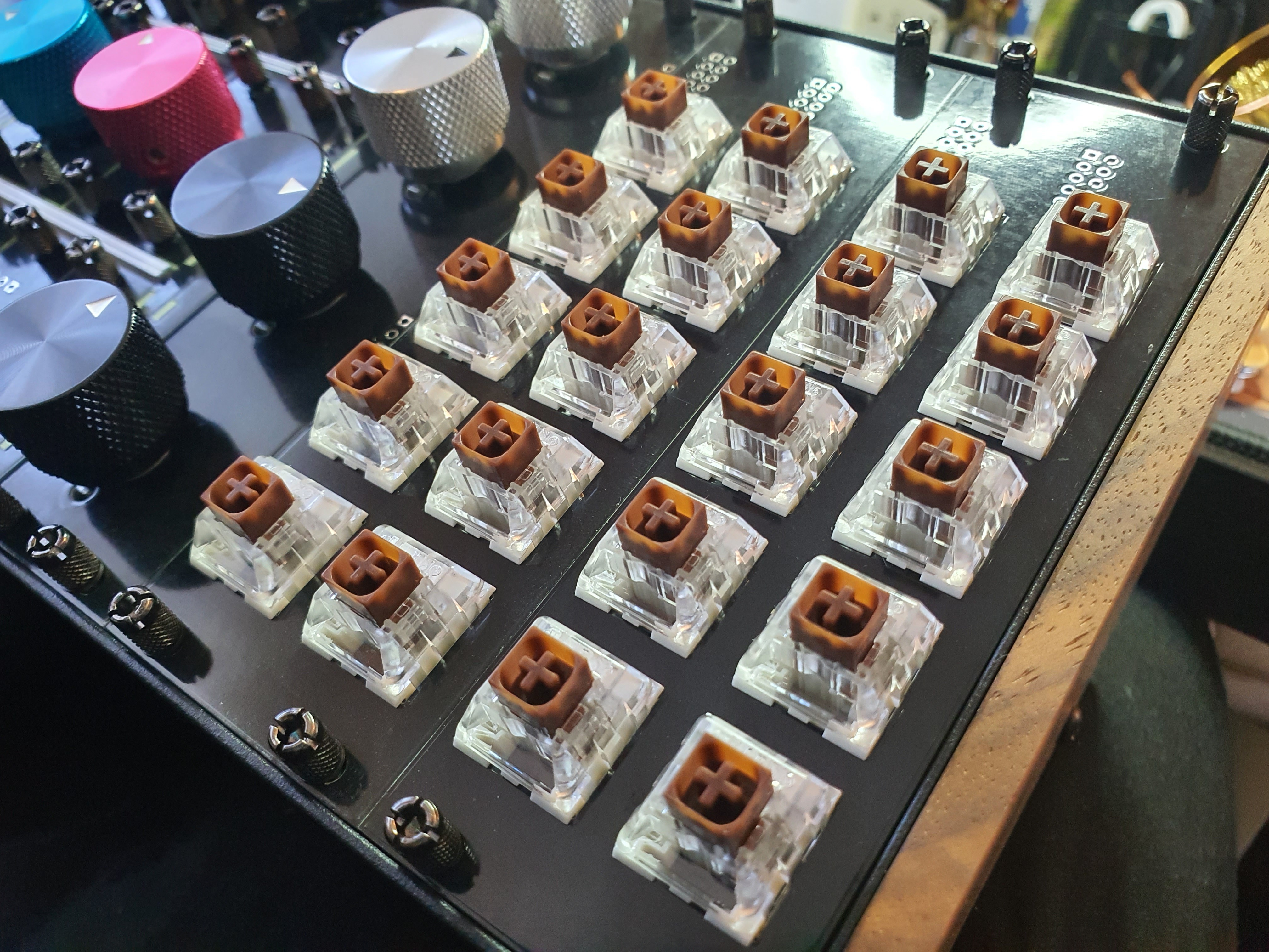
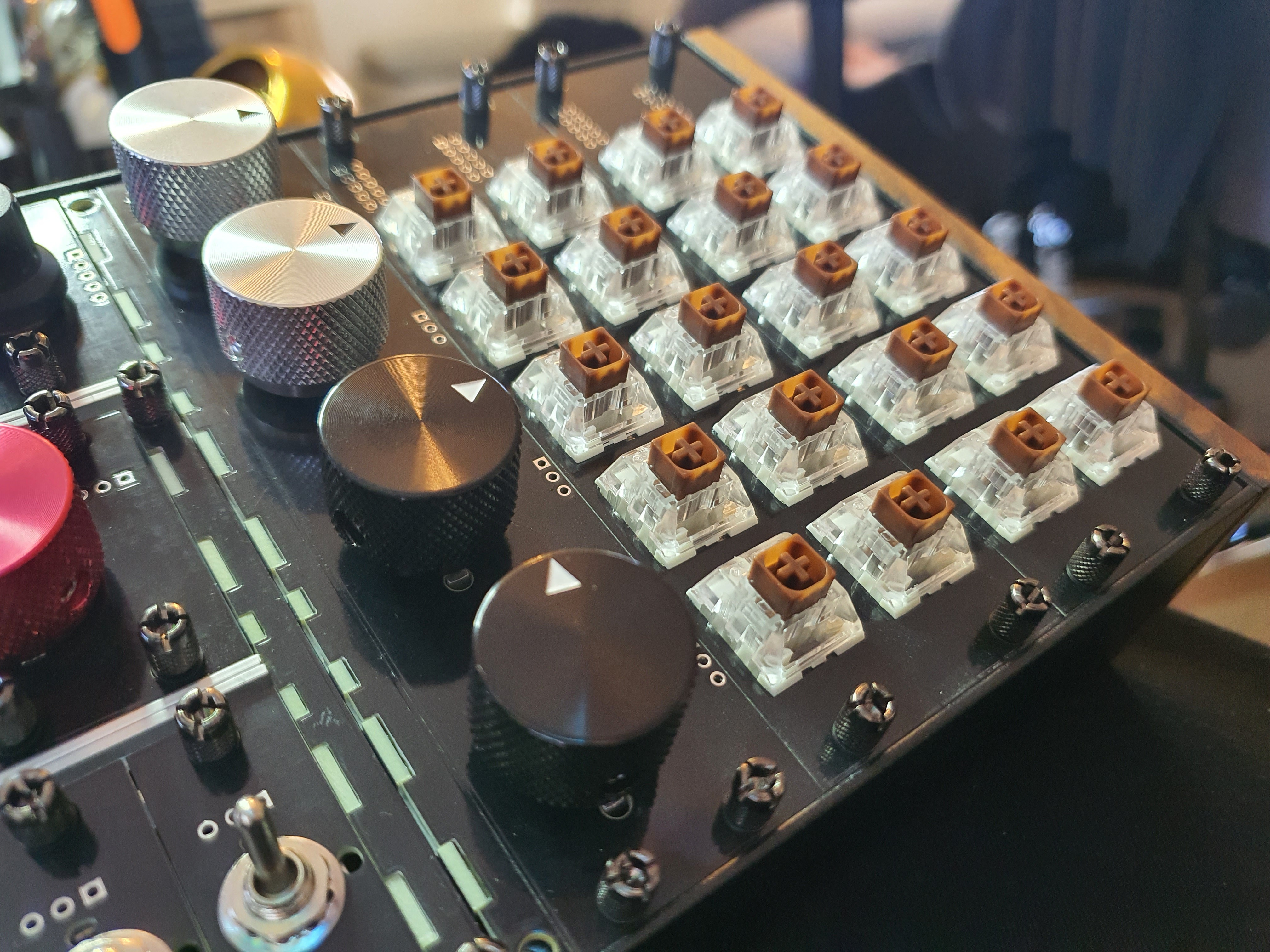
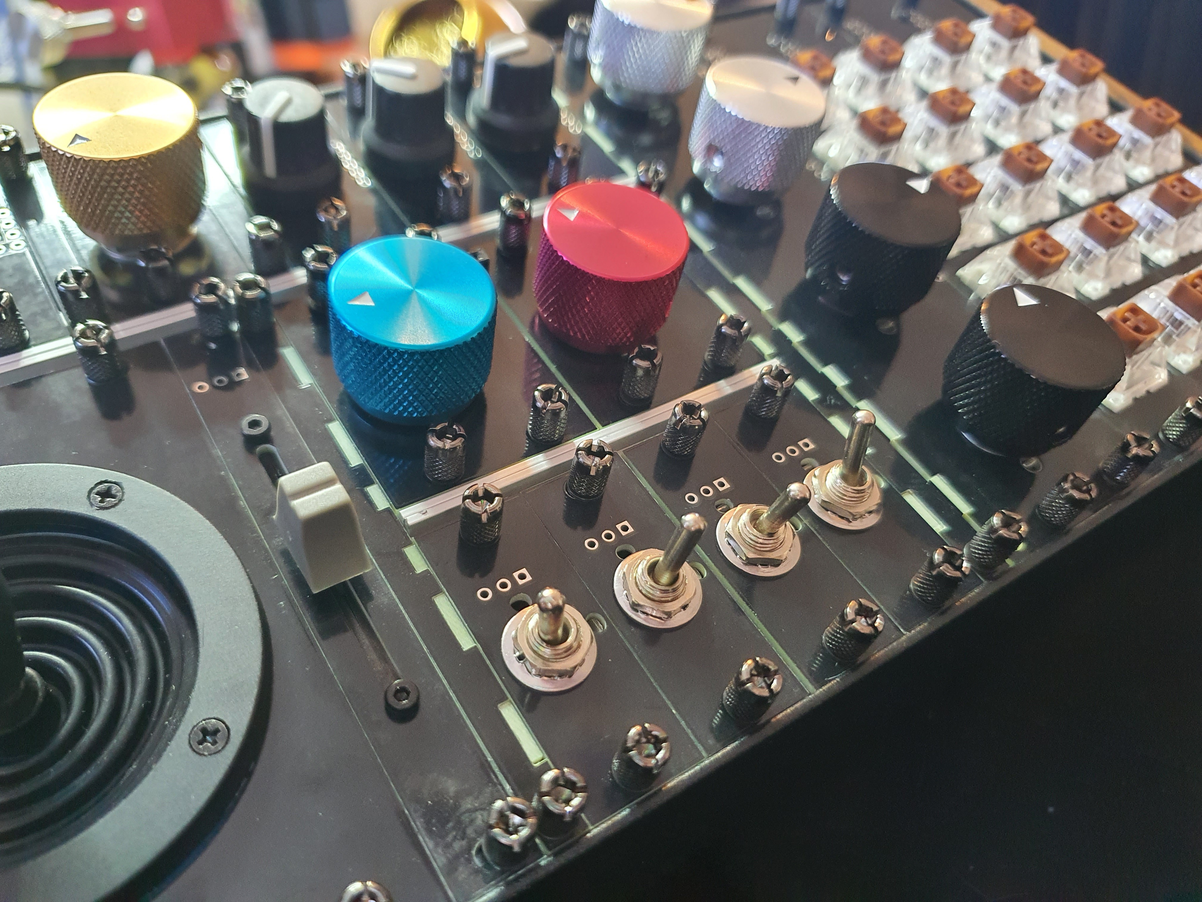
Oooh isn't that just pretty!
It's got the sauce, as the kids say.
I'd post that to my aesthetic tumblr under #tactile.
actually, I might just do that too brb.
Discussions
Become a Hackaday.io Member
Create an account to leave a comment. Already have an account? Log In.