Jorj Bauer
-
Entry 9: Adding a Peripheral
02/20/2017 at 19:49 • 1 commentThis whole thing was a matter of "I can build that with what I've got". And I've got a *lot* of stuff, which explains why there's a currently unused nRF24L01 soldered in there. What else do I have lying around that could become part of this project? Let's see... hey! Hows'bout this guy?
![]()
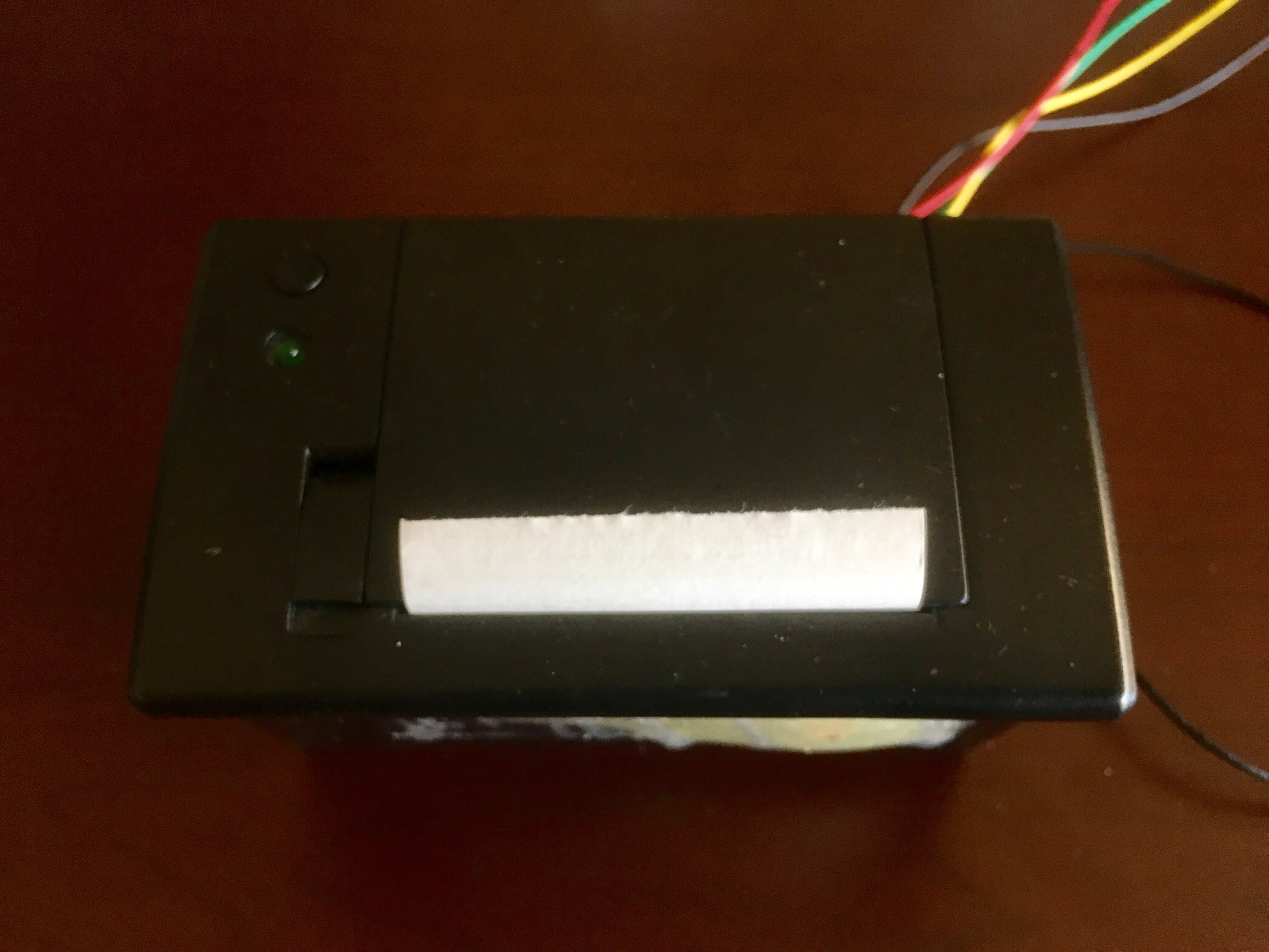
A number of years ago, I bought this thermal printer (probably from SparkFun) as one of those "that's interesting and I don't know what to use it for now, but it'll probably disappear off the market in 12 seconds and I'll regret not having bought one" kinds of purchases. My son had a friend over one weekend, and I briefly used it as part of a scavenger hunt: they found an RFID card, that they had to swipe across the timey-wimey box that my then 9-ish-year-old son used as a time machine. It had an Arduino Uno in it with an RFID reader; he had a key card that he needed to "start" the time machine, before he played with the buttons and dials and made noise and lights with analog dials that went up and down. When they found the clue that gave them a blank RFID card, he knew exactly what to do with it - he swiped it on the timey-wimey machine, which had a mysterious black box connected to it, and BBZZZZZT out came receipt tape with their next clue printed on it!
And since that magnificent performance, this guy has sat in a drawer. With the timey-wimey machine that he stopped playing with. Not coincidentally, they're both in the "partial projects" drawer that I occasionally go to in order to scavenge parts.
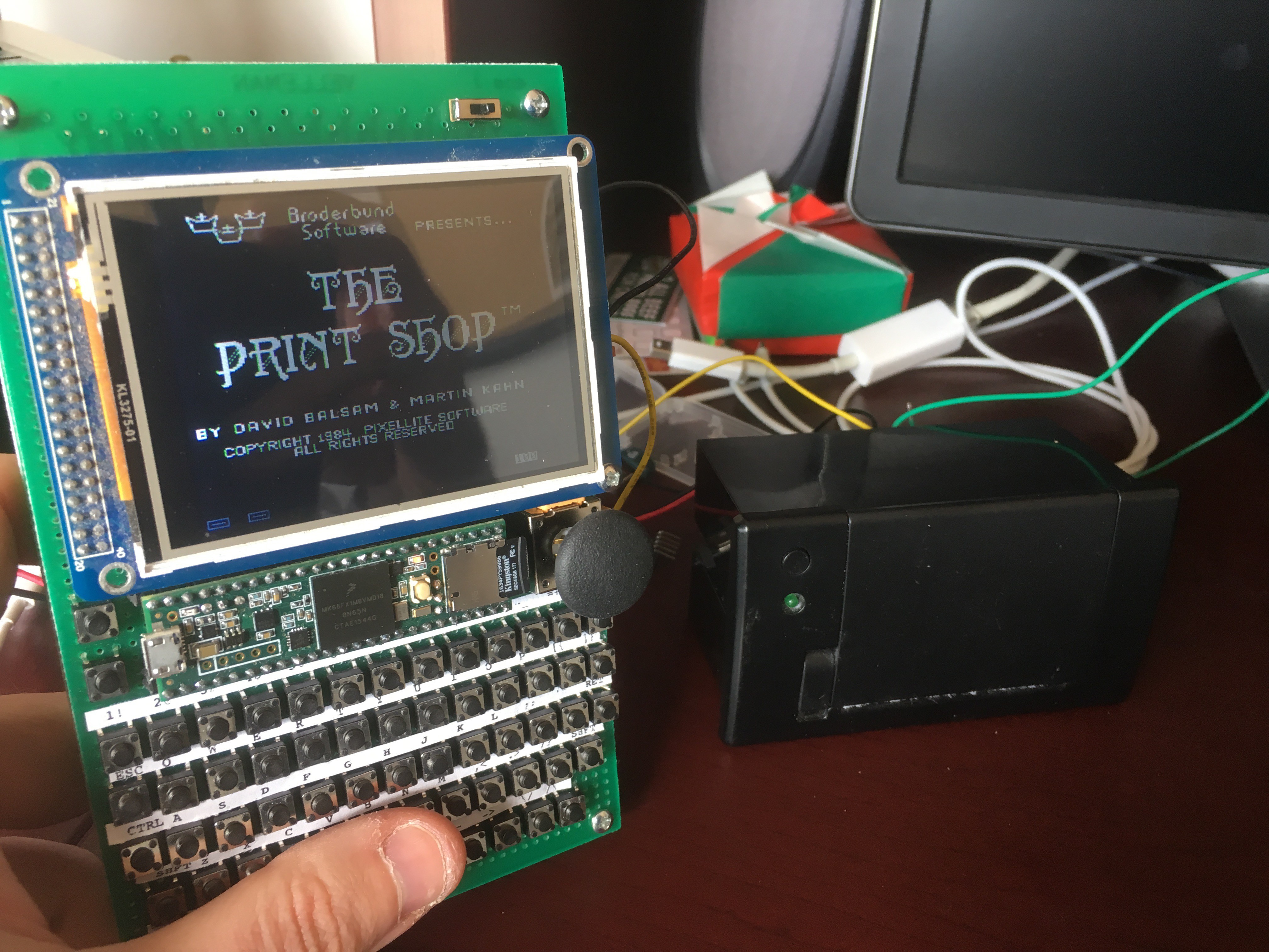
Which brings me to the actual story. Can I glom this guy on to my Apple //e? Back in the day, I had a printer, of course; the Epson FX-80. (Apparently you can still buy ribbons for them on Amazon. Holy. Crap.) What if I made this a virtual FX-80, to go with my Virtual Apple?
Thinking of the physical hardware: first you'd need to add a printer card. That's easy enough - add another object that inherits from the Slot class, which requires a few methods:
virtual void Reset();Boringly called when we want to re-initialize the card to its boot-up state. We can deal with that later.
virtual void loadROM(uint8_t *toWhere);Used to load its ROM image in to the MMU's memory on boot or reset. So what ROM do we load? I *didn't* grab the ROM from my printer card. (I don't even remember for certain what it was. I think it was probably a Grappler+?) Which leads me on the hunt for a printer rom. Fortunately for us, the Apple 2 Documentation Project exists! Buried in there are ROM images for Apple's original (1977) Parallel Card. I think it's the one named "Parallel Mode". The ROM image is all of 256 bytes.
Let that sink in a minute: Woz managed to pack the parallel port interface that became the base standard for printing on the Apple II in 256 bytes. I double dog dare you to write anything actually useful in 256 bytes today. Even the Hackaday challenge was for 1k!
Back to the task at hand:
  virtual uint8_t readSwitches(uint8_t s);
  virtual void writeSwitches(uint8_t s, uint8_t v);
These handle the reads and writes to the mapped memory registers ("switches") that this I/O device uses. For a first pass, I'm going to ignore reading; any read will just return 0xFF. And for writing, it looks like the parallel card sends commands to us at memory address 0xC100 (slot 1, switch 00).
Right! We have a ROM. We have a ParallelCard in a Slot. Time for a virtual printer - fx80.cpp. This is fairly complicated, and does a lot of "take that input, switch in to or out of command modes based on the input, and do the right thing with it". And the easiest thing to have it do is print graphics.
Why is that easier than text? Simple: I want the text to look like the FX-80 text. And for that, I'm gonna need to hand-code their font, one dot at a time. Which is entirely possible, thankfully, because they printed the whole damn thing in a manual. (Aside: Epson, themselves, have the manuals online! What an amazing thing in this day and age.)
Anyway: some manual bitmap coding later, and we have at least partial results in fx80-font.h. (As of this writing: all the upper-case letters are done, along with the numbers and some symbols. Most character definitions are still blank though.) It's enough for testing. Given the way the graphics printing works on the FX80 - where you dump 8-bit data for each column of pins, across all 960 pixels for the page - it makes sense to buffer one line of pixels and then figure out how to print them. Hence rowOfBits[ (FX80_MAXWIDTH/8)*9] -- because I lied, and it's actually 9 dots tall instead of 8 -- and printing a letter is a matter of transferring pixels from fx80-font.h to the right position in that row of bits. Okay, good enough for now.
Next up - how do I test any of this? I'm going to want an OpenCV equivalent of the printer, before I start dumping garbage to my very (in)expensive thermal printer paper. Easy enough - whip up another openCV window in opencv-printer.cpp, which has an interface (PhysicalPrinter) that expects addLine(pixels); moveDownPixels(count); and update().
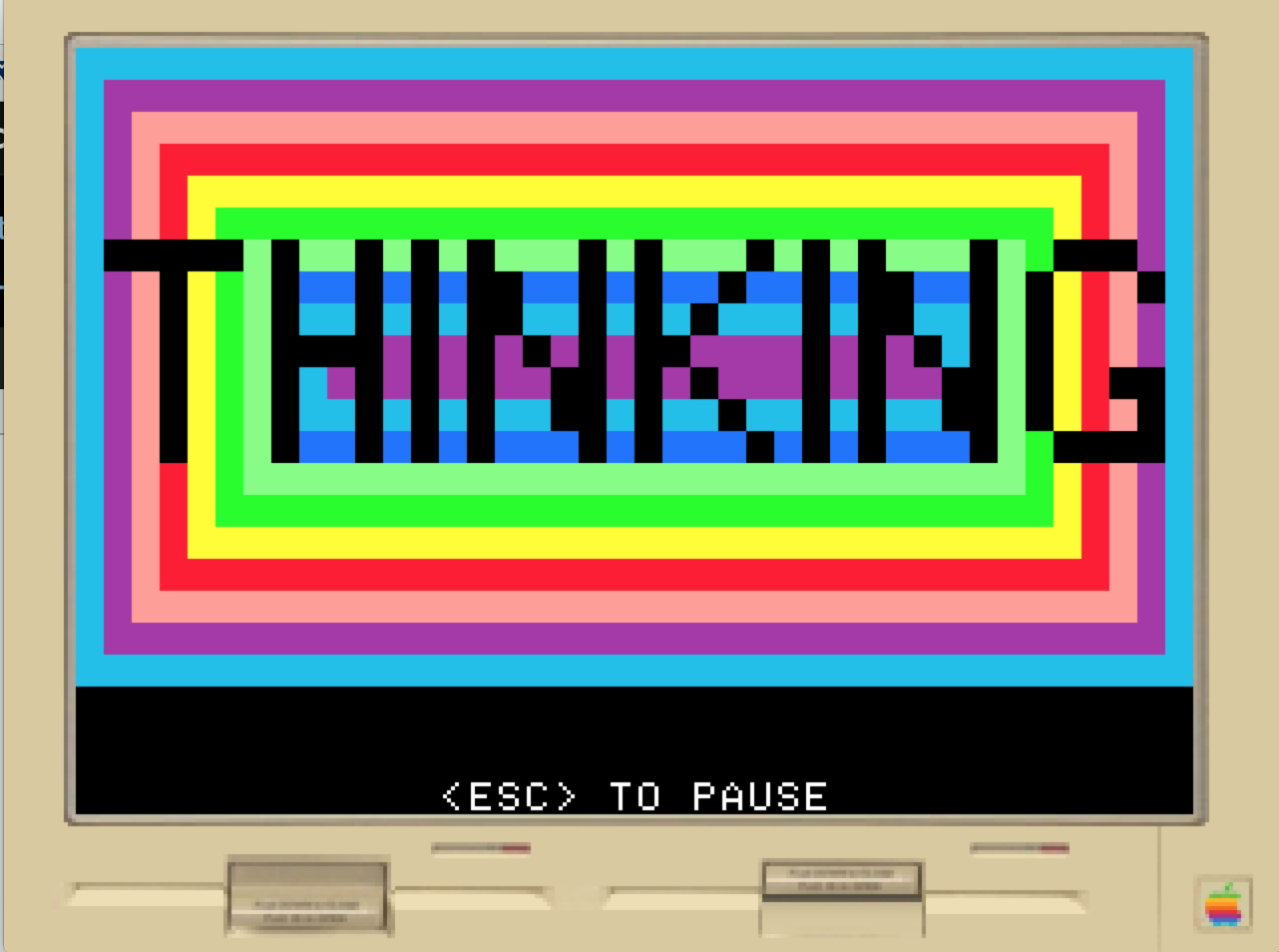
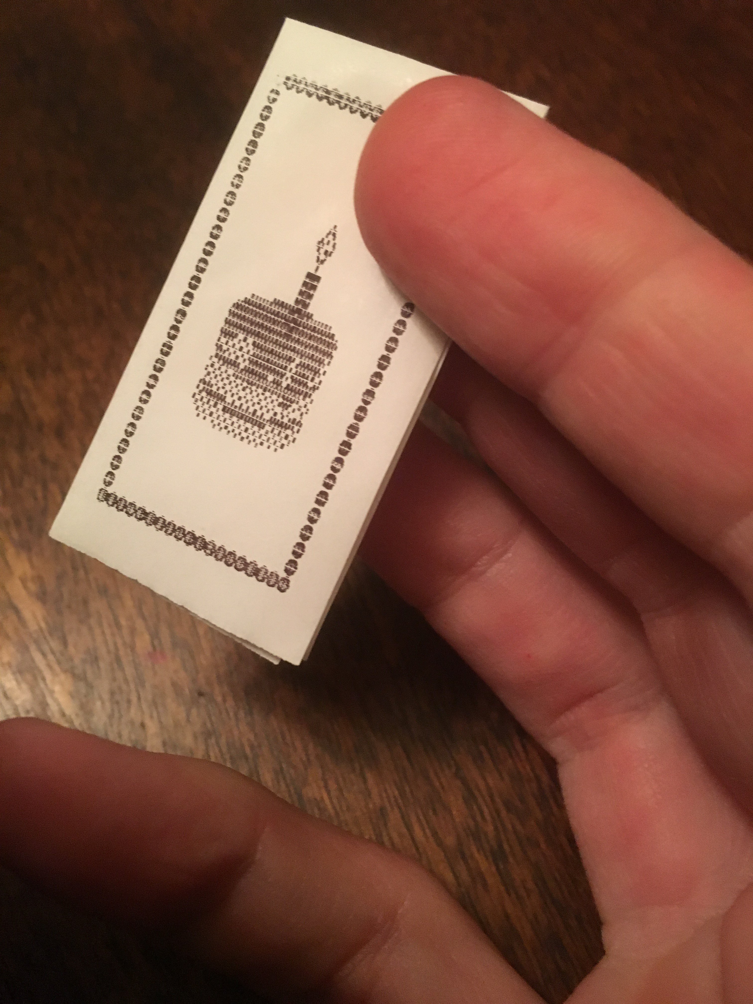
Wire it all together, fire up PrintShop, and *bam*:
![]()
Holy shit, it works.![]()
All I need now is a glass of wine, some time to translate those codes to the thermal printer, and ...
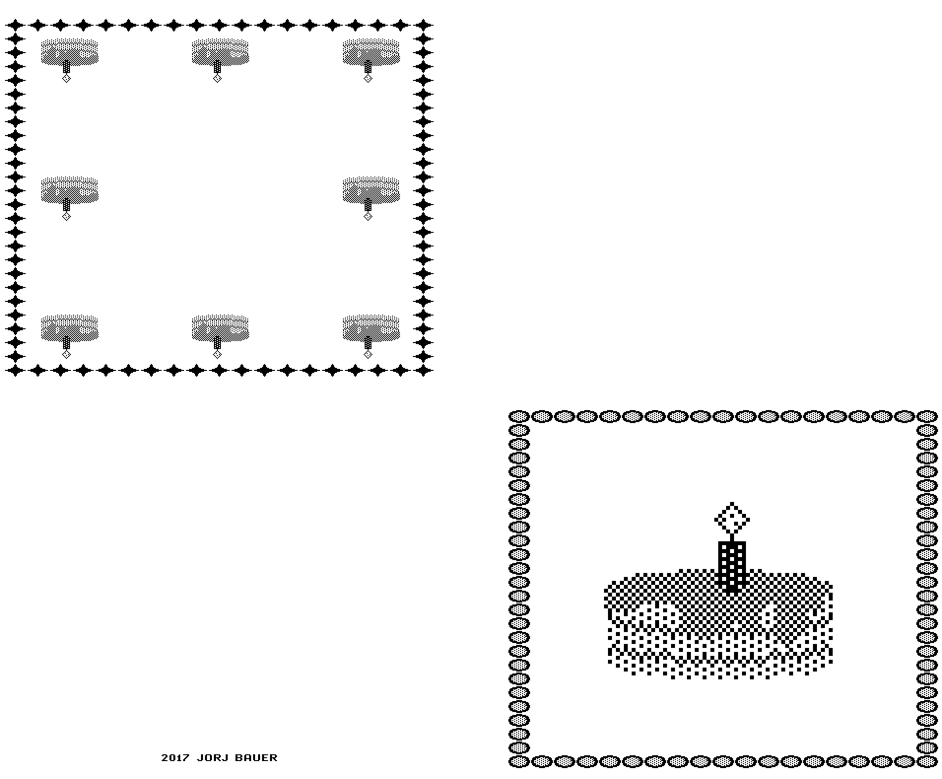
![]()
![]()
Happy Birthday, emulated FX-80!![]()
-
Entry 8: a Teensy bit of support
02/20/2017 at 19:29 • 0 comments(This post refers to git commit 3af0b916d7481305979181e1c307ef40e1b46f19.)
Finally! Here's the important part: all of the hardware model for the Teensy. Well, most of it. There's something I haven't put in quite yet that I'll get to in the next log. :)
This is, for the most part, very straightforward. All of this stuff is in the teensy/ directory of the project.
The file teensy.ino is the glue, just like aiie.cpp was the glue for the Mac-based emulator. It connects together the MicroSD card, keyboard, display, joystick, and Apple //e VM. It's responsible for running instructions on the CPU at the right time. And it's a bit messy.
Let's start down in the virtual 65c02 CPU again. With the Mac version of the emulator, aiie-opencv runs two concurrent threads - one for the CPU and one for the display, basically. The same division happens on the Teensy; there's a function runCPU() that performs some work on the CPU. (Let's assume that's one instruction for now.) It can't do exactly what the Mac version does - which is to run an instruction and then nanosleep() until it's time for the next instruction. The Teensy variant is running from a timer interrupt handler; it has to return, so that the main loop() can continue to redraw the LCD screen. So instead, the Teensy code keep track of when the next instruction *should* run, in microseconds. When the runCPU() function is called, it checks to see if it's time to run an instruction; and if so, it does. If not, it simply returns.
But there's a lot of overhead in calling the virtual 65c02 to perform one instruction. We have several function calls, each of which has to save and restore register values, in addition to the memory jumps and returns. If you run the CPU flat-out in one function, it performs much better than if you call it one step() at a time. And, indeed, if we call one step() at a time we have none of Teensy's CPU time left to draw the screen. We're running at a fraction of the speed of the original Apple //e. Which means that we need to compromise.
Instead of calling the virtual CPU one step at a time, we tell it to execute a few instructions before it returns. The "Run(24)" call tells it to execute enough instructions to take up at least 24 clock cycles before returning. (The number comes from experimentation; the average time used per instruction is about 3 cycles, and this happens to be the largest multiple of 3 that didn't have other unwanted effects.)
Couple that with Timer1. This drives the CPU. Timer1 has a resolution of 1 microsecond, which is *just a little* too slow for us; the Apple //e clock is actually 0.97752 microseconds. And it's actually immaterial, because of the Run(24): we're already sort of driving in a traffic jam: we move a little, then stop. Then move. Then stop. The trick is to look at this from high enough above that it looks like everyone is moving, just very slowly; we want to be correct *on average*.
That also means that we don't care that Timer1 has a maximum resolution of 1 microsecond; in fact, we can back off a little. And I did. It's called every 3 microseconds, with little to no visible impact. That leaves extra time for the LCD to draw, and in practice the current version can draw about 26 FPS reliably.
It only gets that speed because of optimizations, though. Using the stock LCD libraries, we'll only get a fraction of it; the libraries try their best to be *accurate*. Which means they make very few assumptions about how you're likely to draw. Want to draw a pixel on the screen? Sure! We'll set the cursor position, set the ram position, put you in write mode, and draw the pixel. Want to draw the next pixel over? Same thing. Only... well, the LCD automatically incremented the memory address, so all you really had to do was draw the actual pixel. All that cursor/ram/mode nonsense is superfluous. And in teensy-display.cpp, you'll find routines that are probably only useful to this project: they assume that the LCD is going to be used the way that *I'm* using it. They take shortcuts all over the place. And they get fantastic results from my butcher job: I went from something like 2FPS to 26FPS. Very respectable; I'm sure I could clean this up and probably get a little more out of it. There's a clean/dirty flag that I expect to help quite a lot, but it doesn't work right just yet. And the LCD code is messy; I should clean a lot of it up and better document the way I'm initializing the display (which is subtly different than gLCD).
But not right now! I've got a working emulator, and I'm playing with it in many other ways. :)
-
Entry 7: The Virtual Machine
02/20/2017 at 00:21 • 0 comments(This post refers to git commit 8e155646c9843c095ee4733481913707f49bfe1d.)
This one is kinda big, and I'm going to just give a high-level overview. You can go dig through the weeds yourself, or send me questions that I'll probably ignore for far too long before ignoring you. (Sorry about that, it's not you.)
The virtual machine architecture is broken in half - the virtual and physical pieces. There's the root VM object (vm.h), which ties together the MMU, virtual keyboard, and virtual display.
Then there are the physical interfaces, which aren't as well organized. They exist as globals in globals.cpp:
       FileManager *g_filemanager = NULL;
       PhysicalDisplay *g_display = NULL;
       PhysicalKeyboard *g_keyboard = NULL;
       PhysicalSpeaker *g_speaker = NULL;
       PhysicalPaddles *g_paddles = NULL;
There are the two globals that point to the VM and the virtual CPU:
       Cpu *g_cpu = NULL;
       VM *g_vm = NULL;
And there are two global configuration values that probably belong in some sort of Prefs class:
       int16_t g_volume;
       uint8_t g_displayType;
I've done most of the testing on my Mac, rather than on the device itself - it's easier, faster, and has a full debugger - so there's a Makefile here that will generate an emulator under macOS 10.11.6 with Homebrew and OpenCV installed:
  $ make opencv
  $ ./aiie-opencv /path/to/disk.dsk
As the name implies, this requires that OpenCV is installed and in /usr/local/lib. I've done that with Homebrew like this:
$ brew install opencv
"Why OpenCV?" you might ask. Well, it's just because I had code from another project lying around that directly manipulated OpenCV bitmap data. It's functional, and the Mac build is only about functional testing (for me). I just needed a window that I could draw in!
A little bit about the file structure: the code is separated in to three subdirectories. There's 'util', which holds the 6502 functional test harness and the script to generate the ROM headers; the 'apple' directory, which contains the Apple //e VM code; and the 'opencv' directory, which holds all of the Mac-specific code. The remainder of the code is splayed out in the project root: the CPU, File manager, base Physical and Virtual object definitions, etc.
When the main program starts - in opencv/aiie.cpp - main() creates the physical and virtual objects (a DummySpeaker, OpenCVFileManager, OpenCVDisplay, openCVPaddles, Cpu, AppleVM, and OpenCVKeyboard); wires them together; and then starts them running.
The 65C02 CPU runs in a dedicated thread (cpu_thread) which executes at least 24 cycles of processor time; calls some maintenance functions to keep the various pieces of virtual hardware working; and then calculates how long it needs to sleep, based on how many CPU cycles really executed and what the clock time was when it started.
It's this sleep that keeps this running at 1023 kHz. Take out the nanosleep() call and this will run flat-out as fast as it can. Which, on modern hardware, is ridiculously fast. And if you want it to run at some other speed - perhaps the 8MHz that the //c could brag about - you'd change CYCLES_PER_SECOND from "1023000UL" to "8184000UL" (or whatever speed you want).
While it's running, the VM will spit out lines of text like this:
hit: 2156381; miss: 0; pct: 0.000000
hit: 4224999; miss: 0; pct: 0.000000
hit: 6233853; miss: 0; pct: 0.000000
If you ever see "miss" become non-zero, it means it's taking too long to run the instructions and isn't sleeping at all. Your hardware is too slow for this implementation, at this speed. (I'd be surprised to see that happen.)
There's no sound here - as you might have guessed from the name "DummySpeaker". And there's no support for the joystick buttons. But everything else works (including joystick position, which is emulated by cursor position within the window).
Next up: time to get it running on the Teensy!
-
Entry 6: The Virtual 65C02
02/19/2017 at 19:30 • 0 comments(This may take a little while; now that I'm reasonably happy with the code, I'm refactoring it while I describe it. I've just created a public github repo to hold it all. This entry refers to git commit 85a97abe13528bdf35c525f42aea7ffb003eafff.)
Emulating a CPU isn't difficult. It's mostly a matter of interpreting the next instruction, one instruction at a time, over and over again. The 65C02 is pretty straightforward: it has three 8-bit registers named a, x, and y; an 8-bit stack pointer, sp; an 8-bit status register that holds flags about the current state; and a 16-bit program counter (pc) which has the address of memory that's currently being executed.
One step of the CPU means getting the byte of memory at the PC; executing it so that it changes A, X, Y, STATUS, SP, and PC depending on the instruction; and incrementing the PC to the start of the next instruction.
All of that is in step().
The CPU can address 16 bits of memory. An easy version of the CPU would just have a 64k array that it reads from and writes to. But the memory on the Apple II is not that straightforward. If, for example, you read from memory address $C000 you'll get whatever key is pressed. If you write to anything between $C0C0 and $C0CF, you're interacting with whatever's in slot 6. All of which means we need an intermediate Memory Management Unit to broker all reads and writes. And that's what we now have: a CPU with an MMU model.
Pulling that together with a simple test harness lets us check that the CPU works properly. There's a great utility written by Klaus Dormann that tests all of the 6502's functionality. There are precompiled binaries in there that I've dropped in to the test harness that prove it works correctly:
$ make test
g++ -Wall -I .. -I . -O3 -DBASICTEST cpu.cpp util/testharness.cpp -o testharness.basic
g++ -Wall -I .. -I . -O3 -DVERBOSETEST cpu.cpp util/testharness.cpp -o testharness.verbose
g++ -Wall -I .. -I . -O3 -DEXTENDEDTEST cpu.cpp util/testharness.cpp -o testharness.extended

Start test 2
Start test 3
Start test 4
Start test 5
Start test 6
Start test 7
Start test 8
Start test 9
Start test 10
Start test 11
Start test 12
Start test 13
Start test 14
Start test 15
Start test 16
Start test 17
Start test 18
Start test 19
Start test 20
Start test 21
Start test 22
Start test 23
Start test 24
Start test 25
Start test 26
Start test 27
Start test 28
Start test 29
Start test 30
Start test 31
Start test 32
Start test 33
Start test 34
Start test 35
Start test 36
Start test 37
Start test 38
Start test 39
Start test 40
Start test 41
Start test 42
Start test 240
11 seconds
Ending PC: 0x3399
And that's success! -
Entry 5: Whither Goest My Pins?
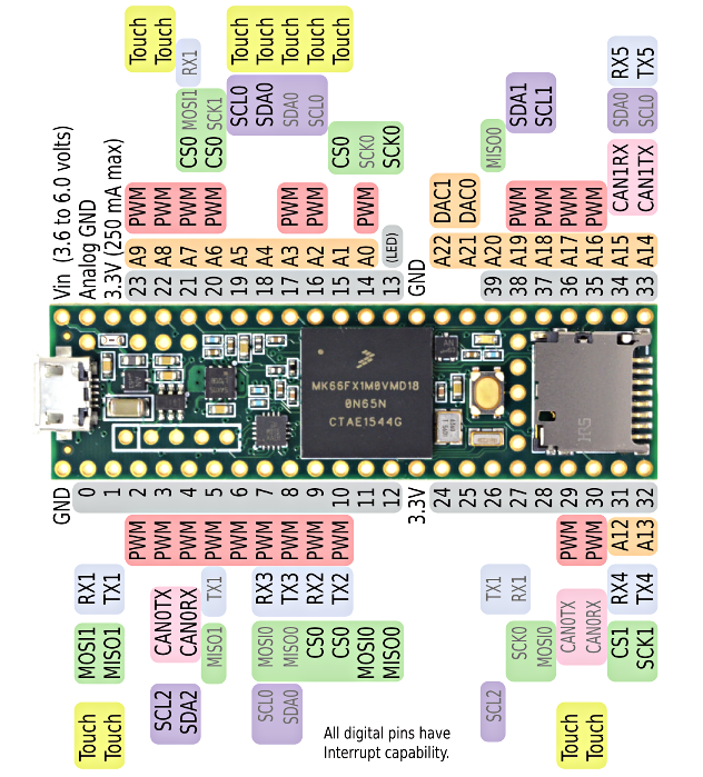
02/19/2017 at 16:13 • 0 commentsIf you go take a look at the Teensy 3.6 pinout, you'll find that it has a bajillion I/O pins.
![]()
Wow.
When I first saw all those pins, I thought something along the lines of "that's great, but it's gonna be a nightmare if I ever actually need all of those." I wasn't entirely wrong, but it's also a godsend that they're all available.
The display eats up all of ports C and D - pins 2, 5, 6, 7, 8, 9, 10, 11, 12, 13, 14, 15, 20, 21, 22, and 23. It also needs its RS (16), WR (17), CS (18), and RST (19) wired up. 20 pins down.
The keyboard needs 13 columns wired up - pins 0, 1, 3, 4, 24, 25, 26, 27, 28, 29, 30, 31, and 32; and 5 rows - pins 33, 34, 35, 36, and 37.
That just leaves digital pins 38 and 39 unused.
39 I'm using for the reset/menu button, which I want to be separate from the rest of the keyboard. Eventually I'd like this to have some interrupt wired up. Or something. Seems like a good idea.
Pin 38, aka A19, is the battery input. Since the Teensy 3.6 isn't 5v tolerant on its inputs, and Li-Ion batteries go up to 4.2v when fully charged, a couple of resistors form a divider network to safely provide input here.
And now we're out of pins, but not out of peripherals to connect. What about the speaker?
Fortunately there are two 12-bit digital-to-analog pins! Ping A21 and A22, aka DAC0 and DAC1. I'm using DAC0. And now it feels like we're on borrowed time, having found an "extra" pin.
But we still have the joystick, and we're forced to decide which compromise to make.
The joystick needs two analog inputs. A22 is output-only. I could move something there as an output and reclaim one pin; and then move the reset/menu button in to the keyboard matrix, reclaiming another. I'm not liking that plan, but it's possible.
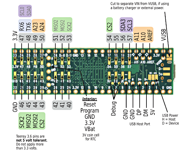
Or, we could look at the back side of that Teensy 3.6 pinout card...
![]()
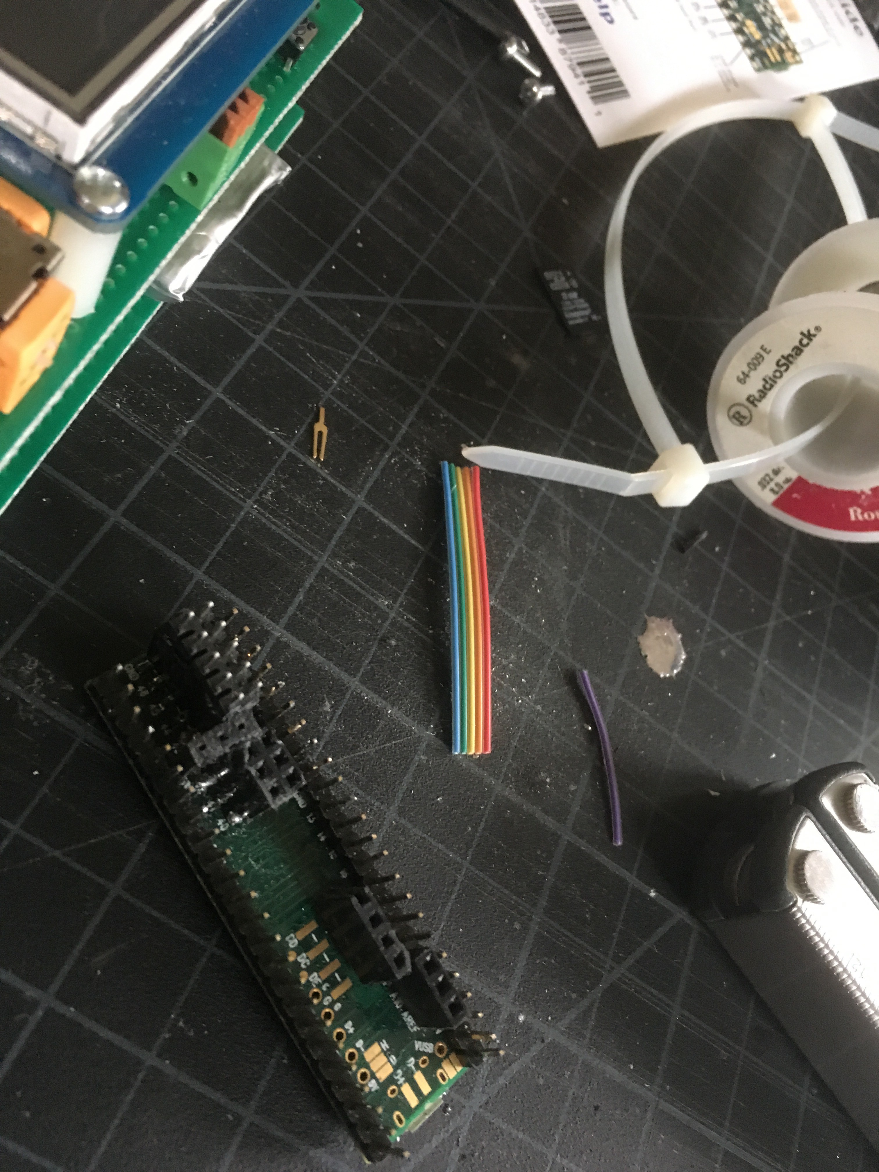
Look at all the bonus pins! All of those pads, just sitting and waiting for an insane person to try to do something like, well, maybe this:
![]()
and this:
![]()
There were some casualties along the way. Because I was soldering in these pins after having put the other headers on the Teensy, there wasn't really enough room for the soldering iron. Some bits of plastic were accidentally melted; the pad for pin 54 was ripped off. But now we have a new lease on life! Extra pins everywhere.
The joystick gets A23 and A24. (I had originally put it on A10 and A11, but while troubleshooting the bad joystick problems I moved it.) And now we get in to insane-overtime-bonus-hardware-land.
I'd like to be able to interface this with, well, stuff. I have no idea what stuff. Or how. But I know that, when everyone was raving about the nrf24l01 last year, I bought two of them and stashed them to play with some day. So one of them goes in on pins 40, 41, 42, 51, 52, and 53. And a quick press-insert header sneaks under the edge of the LCD, giving me access to ground and pins 56 and 57.
![]()
AND WE STILL HAVE ROOM FOR MORE. The Teensy 3.6 is a beast. Nicely done, Paul!
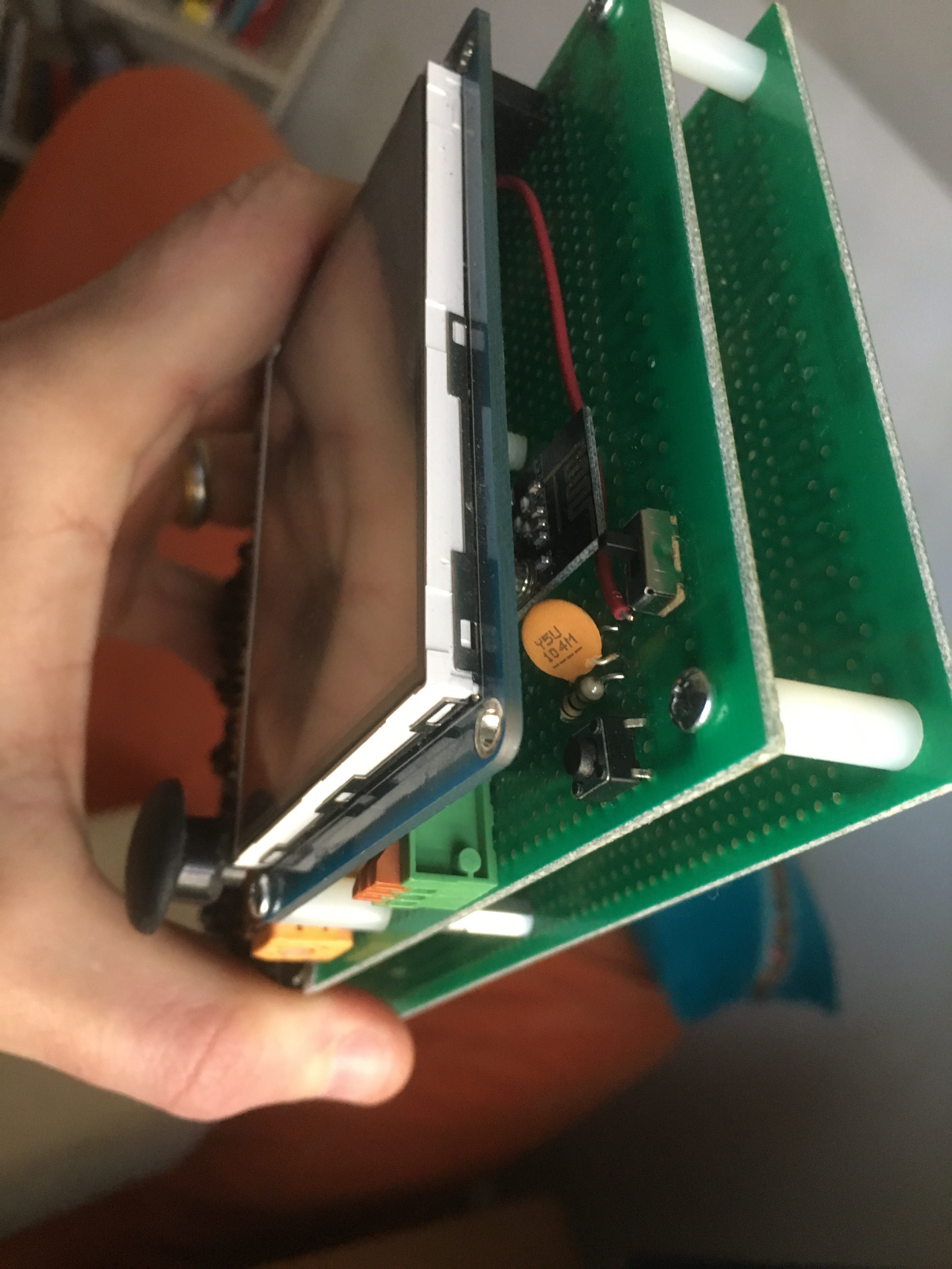
But this all comes at a price. The second board, and standoffs, were added to protect this:
![]()
... so I took the botched first board, where I thought I was going to use that LCD interface - but found it unnecessary, threw the board in the trash and started over, and then rescued the trashed board when I needed a backplate. Because, y'know, nothing goes to waste? Or something. I figure it's good enough until I figure out what kind of case this will go in. (I'm not entirely sure that I ever will. It'll probably live its life like this, case-less.)
Two last details of the hardware: there's a backup CR2032 battery hiding under the LCD, for the Teensy's built-in clock; and I replaced the 1000mAh lithium-ion battery with a 3000mAh removable 18650 cell. I also ditched the USB charger, opting for a removable battery. Again, this isn't quite perfect; the battery holder is about 21mm wide, while the standoffs are 20mm. Add in the height of the solder under the keyboard and it *really* doesn't quite fit. So the standoffs at that end aren't tightened down all the way, and the boards flex a little to accommodate. Not ideal, but I don't have any 22mm standoffs, so it'll have to do!![]()
At some point I'll draw up the schematic and post it. And update the list of materials. Eventually. Don't hold your breath. :)
-
Entry 4: The Keyboard and Joystick
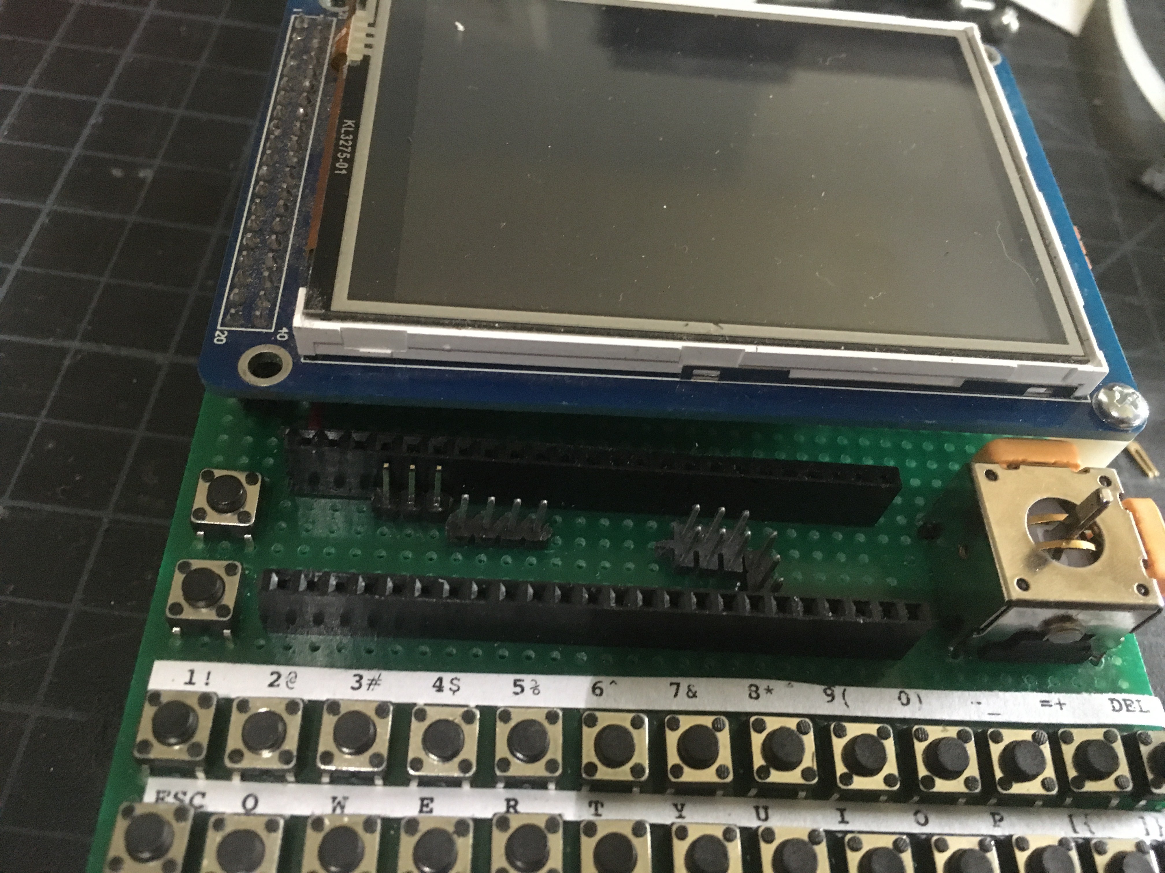
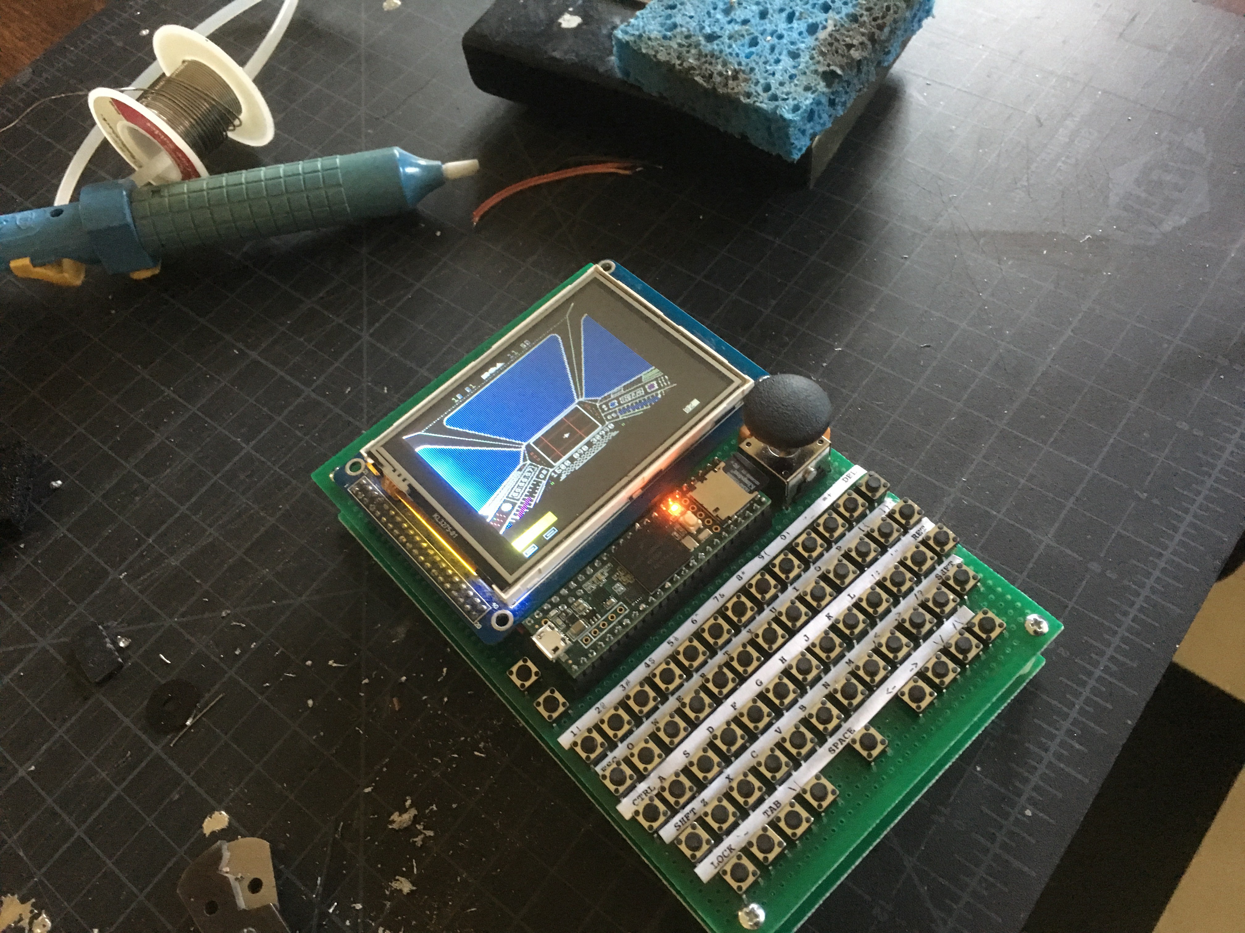
02/19/2017 at 15:06 • 1 commentContinuing to ignore the software for a moment: time came to wire up the keyboard.
![]()
This turns out to be very straightforward, if a bit pin-intensive. I wanted all of the keys on an Apple //e keyboard. The joystick buttons are the same as the open- and closed-apple keys; those are to the left of the teensy. The rest are all right there: 13 columns and 5 rows. There's also a reset/menu button that's in the upper-right, unfortunately just under the LCD (it seemed like a good idea at the time).
The Apple //e couldn't handle multiple simultaneous keypresses. There was a dedicated processor for the keyboard, which loaded data in to the data bus for one and only one key at a time. But I don't know what else I'll do with this hardware, so I'd like to at least have it capable of multiple keypresses, even if the virtual Apple //e I'm building won't be able to take advantage of it.
The classical way to build such a keyboard would involve a lot of diodes. I had about 30 1n917s and 1n1418s that I could use, but I'd need about 65. I actually bought 100 more 1n917s, getting ready to solder them all in. And then I found the Arduino matrix Keypad library, which does something very clever! It uses the tri-state nature of Arduino I/O pins to scan the rows and columns to figure out what's pressed. Because it's pulsing each row/column, it doesn't need the diodes to separate the signals. Bonus - saved me a bunch of soldering time! Those diodes go back in the box for the next project that needs them, and I can safely say that I've still built this thing out of the parts in my house.
For a little while, at least. Until I broke the joystick.
The picture you see above has the cap missing from the joystick. That's not the problem. I'd actually lost the cap while it was on the previous project it had been part of; the joystick was still functional. And it made it in to this project fully functional for a while. Then one of the two axes started giving me garbage. Resoldering made no difference, and I bought a replacement from Adafruit... just to have the second one do the same thing after about a day.
Harrumph. Guess I need to find a better joystick.
Unfortunately, by this point I've kind of painted myself into a corner. The design assumes that the joystick fits in that space. I've now soldered the display in, so I can't easily move it up to buy some more. And I can only find two other joysticks that will potentially fit. Both, fortunately, carried by Adafruit.
They look pretty much the same: the Parallax 2-axis joystick and the Analog 2-axis Thumb Joystick with Select Button + Breakout Board. I bought one of each, and when they arrived, there were two issues.
First: the thumb joystick just doesn't fit. It hits the teensy on the left. It hits the LCD just above it. But you can take the joystick piece off, so I'll worry about that later.
Second: neither of the joystick bases fits as-is. The first has an adapter board soldered on to it, and the second has a button that hangs off the right side (making it too wide to fit on my board).
Rather than cutting the button off of the second and re-working its mechanics, I opted to desolder the first from its adapter board.
![]()
Which leaves the joystick cap problem: a little Dremel work to remove its base, and things fit pretty well!
![]()
"What about the MicroSD card?" I hear you cry. I got lucky here: the card - which you may be able to just amke out to the left of the joystick - *just* clears the joystick base. It's possible to get it in and out, but it's not something I want to have to do often.
The joystick's rotation is still slightly fouled by the LCD when trying to move it to the upper left corner. But it's manageable. If I were starting over, I would move the LCD up a hair; and the Teensy would probably go under the LCD, vertically, with the SD card popping out the top. Which would mean hard-mounting the teensy instead of leaving it socketed...
-
Entry 3: LCD workings
02/19/2017 at 13:35 • 0 commentsNow, the SainSmart LCD I'm using wasn't the only one in my house. I have some other LCDs that are SPI-driven, and are about the same size. And I deliberately didn't choose them, because I wanted some bandwidth here. And this is the first obstacle in the "make it fast" department - in addition to emulating the CPU, I'm going to need to jam data out to a display.
The Apple II memory model is reasonably simple: there is a region of memory that's used for text and lo-res graphics, and another region used for hi-res graphics. It's easy enough to write an emulator that, whenever the text/lo-res page is written to, will update the screen - and this is indeed what I did in the first pass of this emulator. But this is only good as a toy: if the VM has to redraw part of the screen every time that the CPU is trying to perform a write to that part of memory, then either the display draw has to be so fast that you complete the combination of (CPU instruction emulation + memory write + LCD update) in less time than the original processor actually used for its single instruction; or you wind up running at less than the correct speed.
So: can I take the simple path and write to the LCD faster than the original CPU? That begs a couple of questions of its own.
How fast is one instruction on the Apple //e? Well: the 65c02 in it runs at 1023 MHz; one clock cycle is essentially 1 microsecond. Instructions on the 65c02 take different numbers of clock cycles, but average around 3 clock cycles. So a write to RAM might take 3 microseconds.
How fast can we write to the LCD? That's more complicated; with the LCDs in my house, I'm looking at either SPI or parallel busses. With an SPI bus you need just a few pins, but you have to clock out every bit: sending all 8 bits of one byte to the display, therefore, takes 8 times as long as if you happen to have a parallel bus that lets you send all 8 bits at once. All other things being equal, then: assume the chips on the displays have the same protocol, and you need to send the same data to set a 24-bit color to an arbitrary pixel on the screen - it's clear that if you need the speed, you want the parallel bus. And the SainSmart I've got has a 16-bit parallel bus, which is all the better.
Now: sending one pixel to this 16-bit parallel bus means doing something like this:
- assert the command line
- put the command byte for "set position" on the bus
- pulse the write line
- clear the command line
- put the horizontal position on the bus
- pulse the write line
- put the vertical high 16 bits on the bus
- pulse the write line
- put the vertical low 16 bits on the bus
- pulse the write line
- put the horizontal ram address on the bus
- pulse the write line
- put the vertical ram address on the bus
- pulse the write line
- assert the command line
- put the command byte "sending data" on the bus
- pulse the write line
- clear the command line
- put the pixel color data on the bus
- pulse the write line
... where I've even simplified the "color data" part. A whopping 20 steps. Let's assume, best case, that each of these takes only one clock cycle on the ARM processor. We also have a function call and return; which also means overhead for saving and restoring register state when that function is called. Let's assume that this is also best case: one instruction for the call, one for the return, one for the save, one for the restore. So we're in the neighborhood of 24/180000000 seconds - which is about 13% of our allotted time for one 65c02 instruction.
All right, it's *possible* that we could draw one pixel. But could we draw one *character*? Assuming that the character is 7 pixels by 5 pixels, we'd have to draw 35 pixels - which puts us at about 4.5 microseconds of work to perform in 1 microsecond of time. In other words: no. Our overly optimistic model says no, and the real-world version is only going to be worse.
Now, there are optimizations that can be made in all of that. Don't reposition the write cursor every time you want to draw a pixel. Use a lower-depth color format so you need to transfer less data. But still - we would need to make a pretty dramatic improvement in order to jam all this data out in real-time.
Which means the complicated way wins. In real-cpu-time, we'll need to update an in-memory framebuffer; and in the gaps between real-cpu-time, we'll update the display as fast as we can. We're going to need all of the speed we can get.
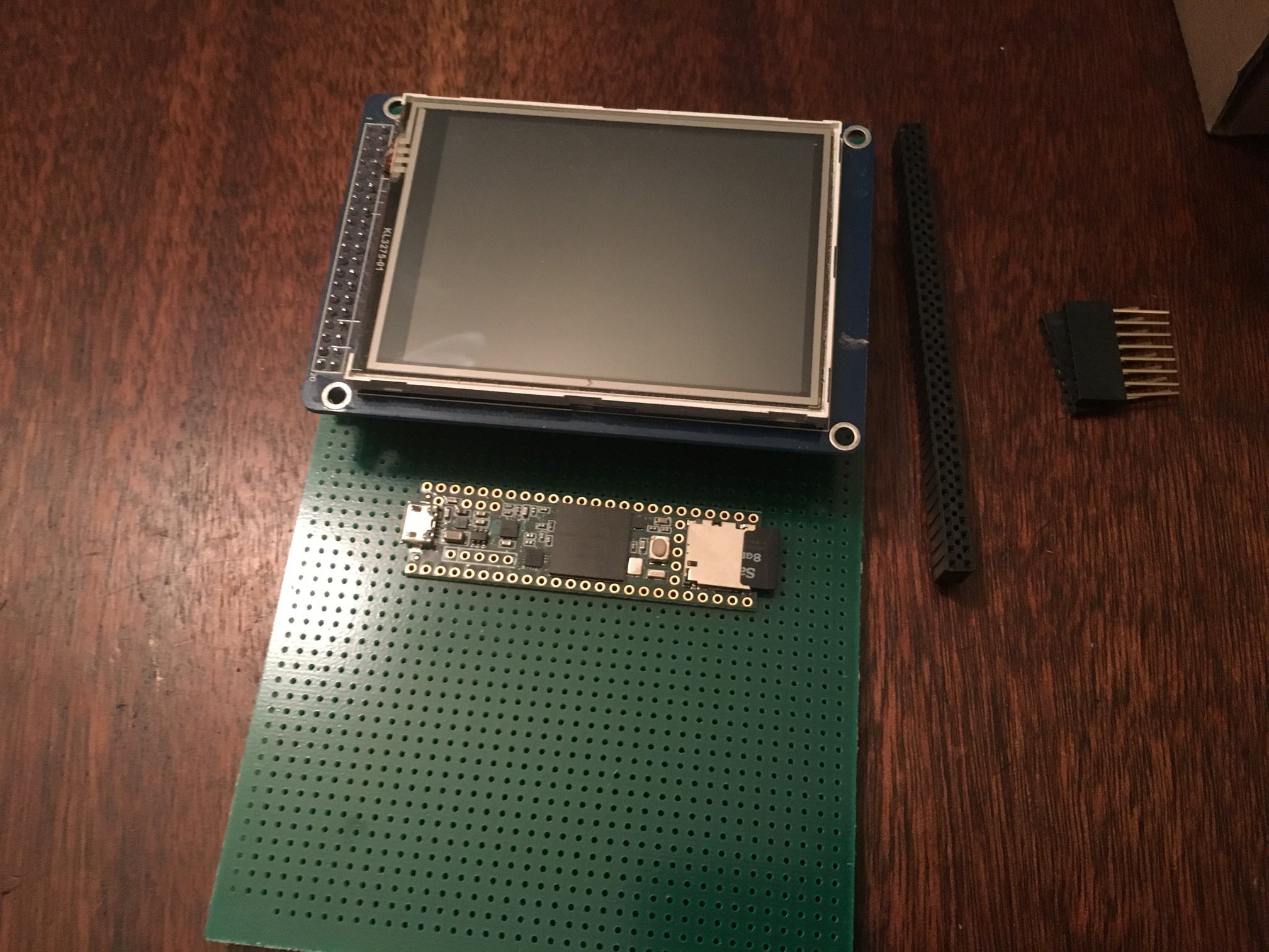
Back to the LCD, then. The SainSmart 3.2" TFT LCD I've got has this adapter board for the Mega 2560 it's supposed to piggyback on:
... it turns out this is basically worthless for this project. Those resistors are all 10k, where they're trying to protect the TFT (a 3.3v device) from the 2560 (a 5v device). The Teensy is 3.3v so all that is unnecessary. That just leaves the blue potentiometer, which is either brightness or contrast control. Away goes the adapter board, we don't need it.![]()
We will need a boatload of pins on the Teensy, though. 16 for the data bus. Reset, Read/write control lines, select line. At least. Fortunately the Teensy has 40 easily accessible I/O pins, so while this is complicated, it's not really a problem. A little bit of prototyping...
![]()
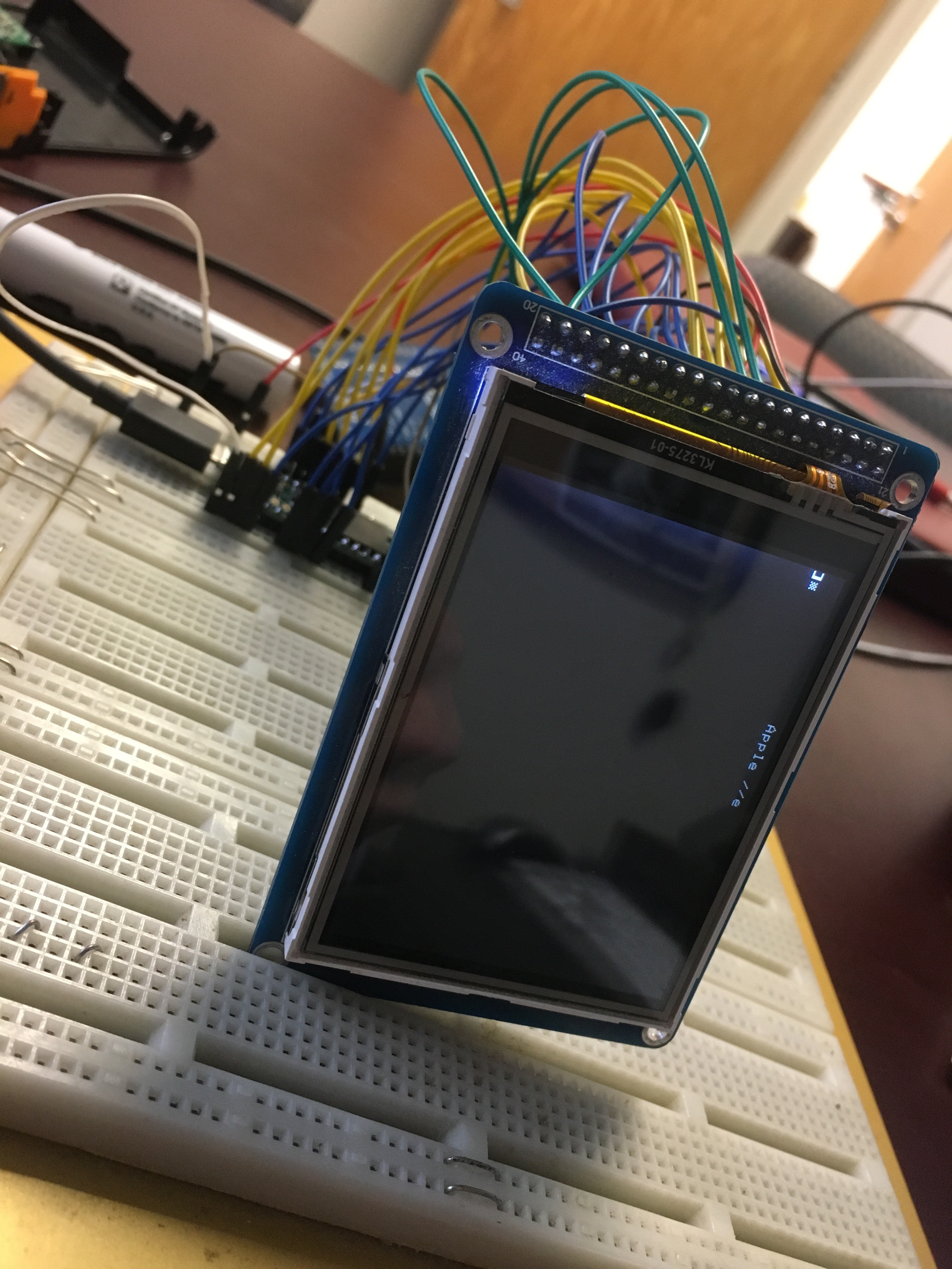
... some test wiring...
![]()
And there we go.
![]()
-
Entry 2: Scavenging For Parts
02/19/2017 at 11:26 • 0 commentsI've dabbled in emulator writing several times. I know that I can write them. I also know, from many programming contests over the years, that I suck at optimizing my code; compilers are much better at optimization than I am. Which is fine, now that compilers do an amazing job at optimization. (In the early 90s, not so much.)
So I started this journey with a reasonable assumption that I would be able to write a full 65c02 emulator; wrap that in an Apple //e housing; and have something that runs properly. The only piece that I didn't know was whether or not I'd be able to make this virtual Apple //e run at its full 1 MHz. Now, if I were writing it on a full-blown modern computer, yeah - no problem. Taking a 2 to 3 GHz processor and emulating a 1 MHz system on it is fairly trivial. On an AVR that's a serious challenge for multiple reasons. Things like the number of instructions needed to emulate various opcodes in your target CPU. The complexities of emulating the Memory Management Unit - where all RAM access has to go through an arbitrator because of funny business in the target computer's architecture. The difficulties of driving displays and keyboards in addition to just running the emulated CPU.
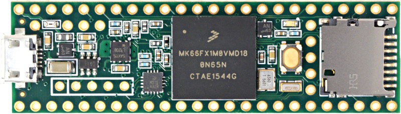
And that's where the Teensy comes in. The Teensy 3.6 is a 180 MHz ARM Cortex M4 32-bit processor. When the 3.5 and 3.6 were released, I put in an order for a couple of 3.6es with no specific plans of what to do with them. I've got a couple projects using the Teensy 3.1, and while they're not high on my list of devices I like to use -- there are some details of how they work that bother me -- I certainly recognize that they're useful as microcontrollers in some situations where other solutions fail. I've got one that drives my Christmas Tree lights (strands of WS2812 LEDs). Another that runs the live Dalek voice changer in Bob the Dalek. And I fully expected that I would one day think of the thing that I needed either more pins, or more than the 72MHz from the Teensy 3.1.
One processor: check.
![]()
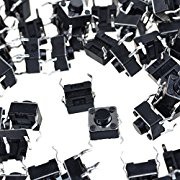
What other parts will I need? Well, I like the keyboard design of Max's 2014 AVR Apple II emulator. I've got a bag of 200-ish 6mm square pushbutton switches. So that's a go.
![]()
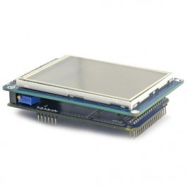
A display, of course. A few years back I built a little Arduino Mega computer that just ran a bit of BASIC that I cobbled together. I had bought a SainSmart 3.2" LCD shield for it. The project was fun to work on, but ultimately wound up in the spare parts bin; not enough RAM on the Mega for me, so I wound up adding an external SRAM, at which point the fun kinda got lost under the complexity, and the parts went out to pasture. Time to bring that LCD back to usefulness.
![]()
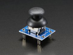
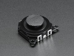
A joystick. Seriously, this is the Number One Thing that keeps me from enjoying many of the games from my childhood. The Apple II emulators that I use have, generally speaking, adequate hacks for joystick support. But if I had an actual joystick on this new thing, I'd be able to actually play games. And - whaddaya know - I've got a PSP 2-axis joystick from Adafruit that I used for the first generation remote control when I built Bob (the Dalek, in case you'd missed that bit).
![]()
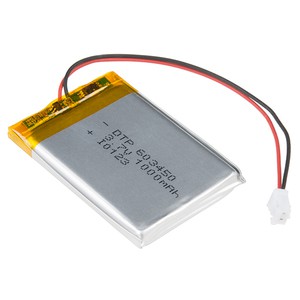
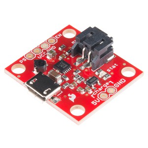
A battery. Well, with all of the projects I've built, I've amassed a small collection of lithium ion batteries. And chargers / regulators. I grabbed a 1000mAh Lithiium Ion battery off the shelf, and a little USB LiIon charger from SparkFun.
![]()
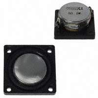
A speaker. My wife is a huge Doctor Who fan. For years, she would take an annual trip to California to the Gallifrey One Doctor Who con. She likes to cosplay Sarah Jane Smith, and so I built her a Sonic Lipstick prop. Which, of course, had to make sound! I embedded an ATTiny, pushbutton, speaker, LED, and battery; the most challenging bit was finding a speaker that was small enough. For the rebuilds, I wound up buying a selection of small speakers from Digikey to see which I liked the most. One of them was the CMS0201KLX, a 20mm square speaker that I really like. It was a bit too big, but I made it work. And, of course, I'd bought two so I would have a spare.![]()
![]()
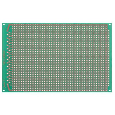
A good sized piece of protoboard. Back in the 80s, it was easy to pop over to Radio Shack and pick up a good quality piece of protoboard. When they restructured their business in the mid-90s and their electronics gave way to games, batteries, and more batteries, I started looking around for a new supplier. While I've found many over the years, I've never been really happy with any of them. The copper pads tend to pull off of the boards really easily. With the old boards, I could desolder and re-solder a pad a few times before I had to worry that the copper would come off with the solder. With basically every board I've bought since then you're lucky if you get to correct one mistake without pulling up the copper.
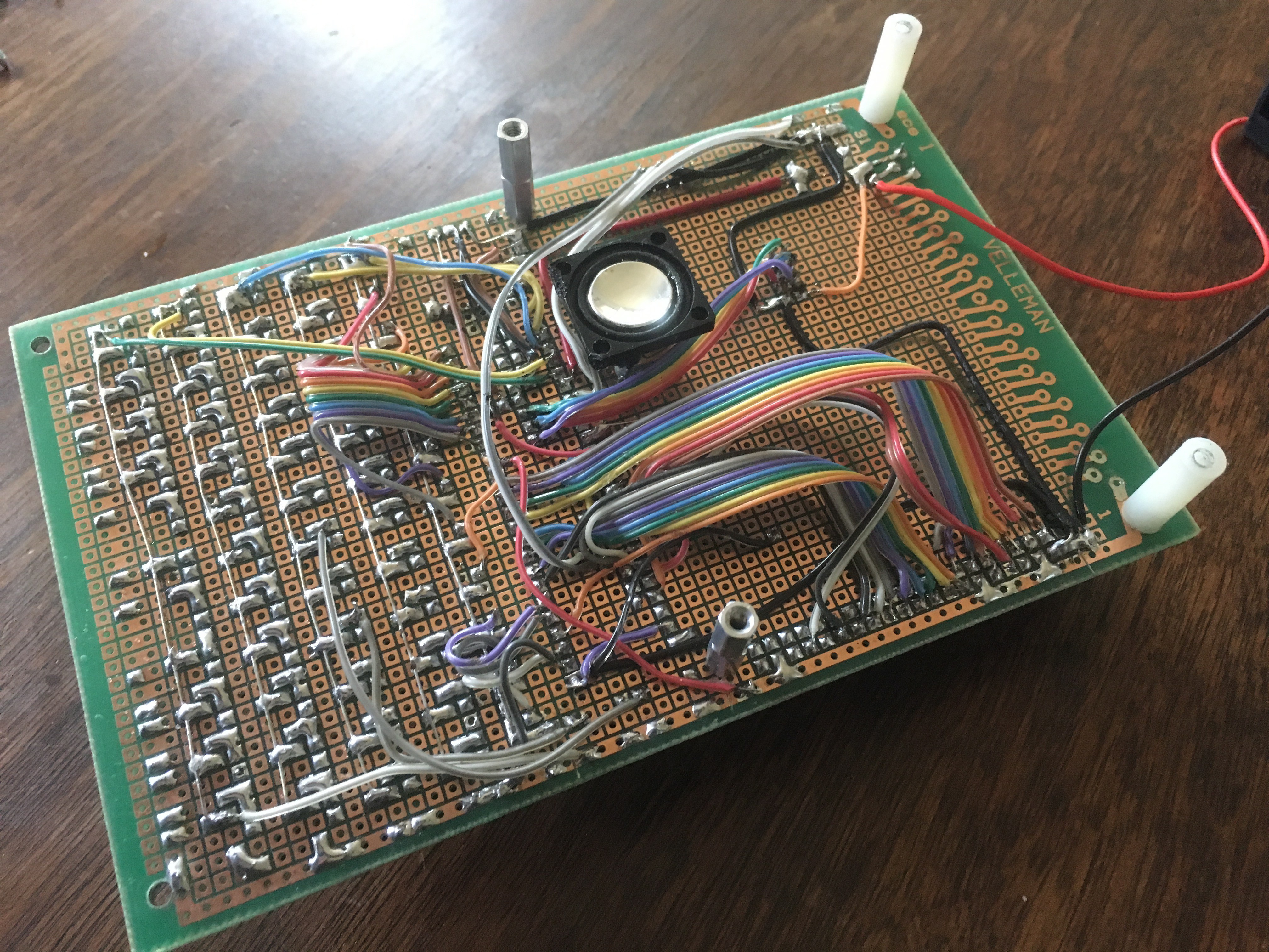
Which is all to say that I have a varied collection of protoboards lying around. I tend to buy a number of them at once when I find something that looks promising. Invariably, they let me down; but I have spares lying around and can start over if I need to. And that's how I happen to have a dozen perfectly-sized protoboards for this project. The Velleman Eurocard, a 3.9" x 6.3" hunk of protoboard.
![]()
The rest is pretty much academic: a slider switch, a couple of resistors and a capacitor to monitor the battery level. And that's my initial bill of materials - all things sitting around the house. Nice.
-
Entry 1: The Inspiration
02/19/2017 at 10:55 • 0 commentsThose of you following my feed (pffft - like anyone would do that) know that, a month or so ago, I spent a sick day at home debugging old Apple II software. Well, it turns out a lot of people are just as crazy as I am; that project now has 2.2k views. That got me thinking about *who* was looking at it, and from *where*. A little bit of stumbling around the interwebs later, I happened upon the Reddit Apple2 sub, where someone had posted a link. And a couple posts before that one was something that truly caught my attention: a post titled "Handheld emulated Apple ][ on ATMega 1284p".
Now, I have no idea how I missed this when it was posted on Hackaday back in December. It would have totally captivated me then. But having seen it now, I knew two things.
1. This is all wrong, because it only addresses 12k of RAM and runs at 70% of the correct speed.
Don't get me wrong - that's still an impressive feat for having jammed it in to an AVR. It's a really cool proof of concept. Which brings me to
2. I had all the parts in my house to build a version that ran at full speed and addressed all 128k of an extended Apple //e.
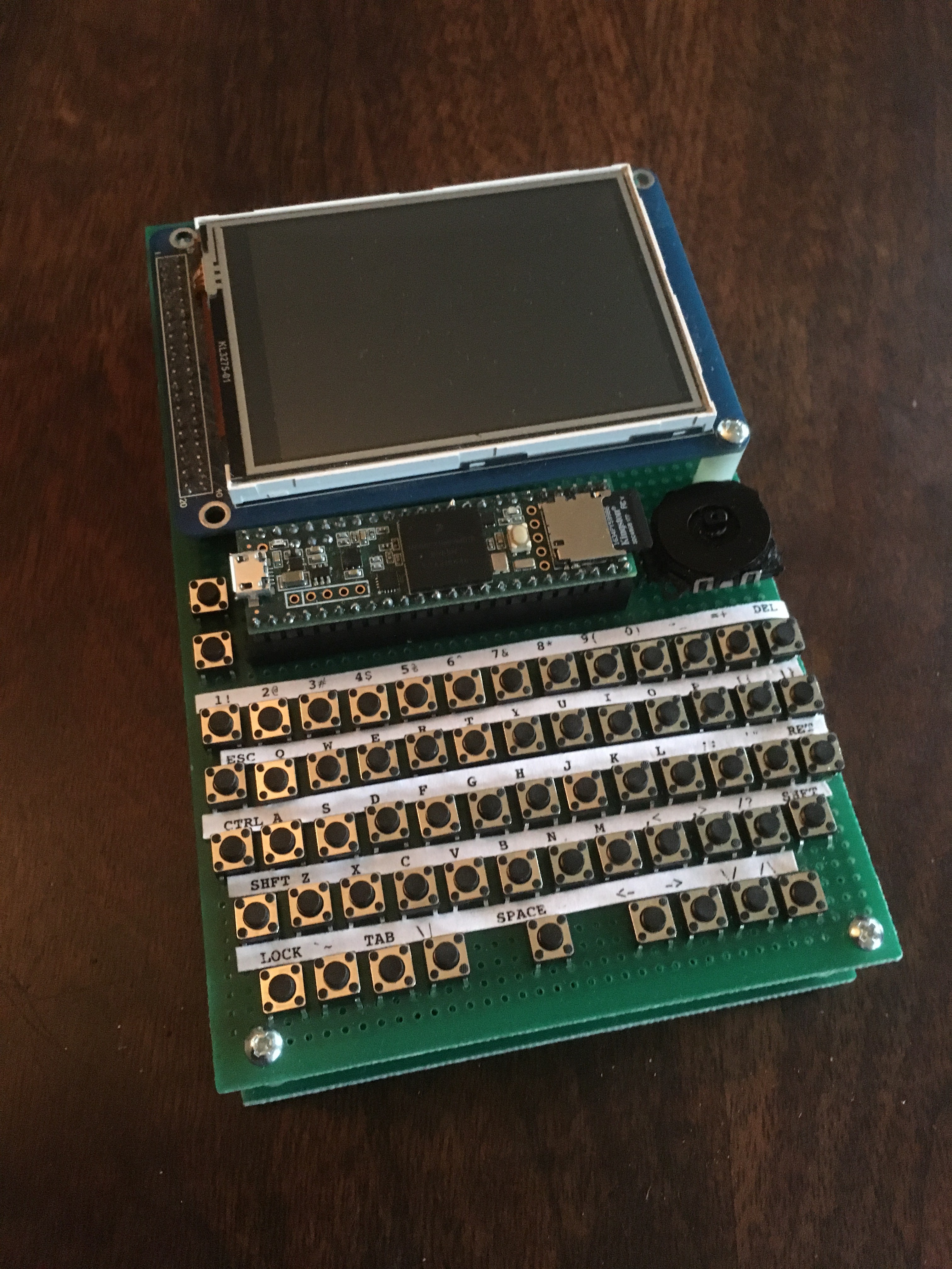
While I wasn't entirely sure if I should be happy or appalled with all the spare parts lying around my workshop, I knew with certainty that I'd be building this. And this is the build log for what is now a fully functional, 100% speed, 128k of RAM, Apple //e emulator.
Aiie! - an embedded Apple //e emulator
A Teensy 4.1 running as an Apple //e