I've spent entirely too much time finishing up the schematic and layout; real life tends to intrude entirely too often and for too long. Wouldn't give it up for the world tho - I've a wonderful and quite understanding family. ;)
At any rate... updates:
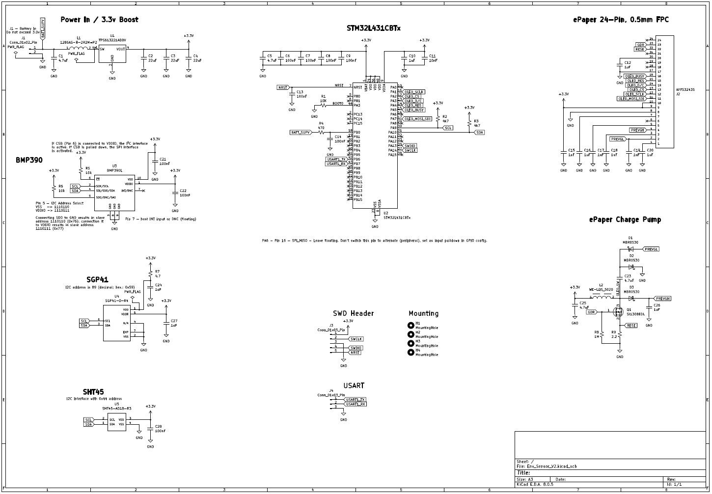
- I've swapped out the TPS610994YFFR (which was a tiny BGA part) for a more sane SOT-25 part, the TPS613221A.
- Schematic completed.
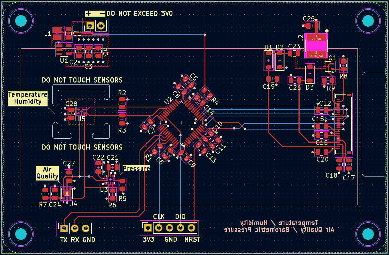
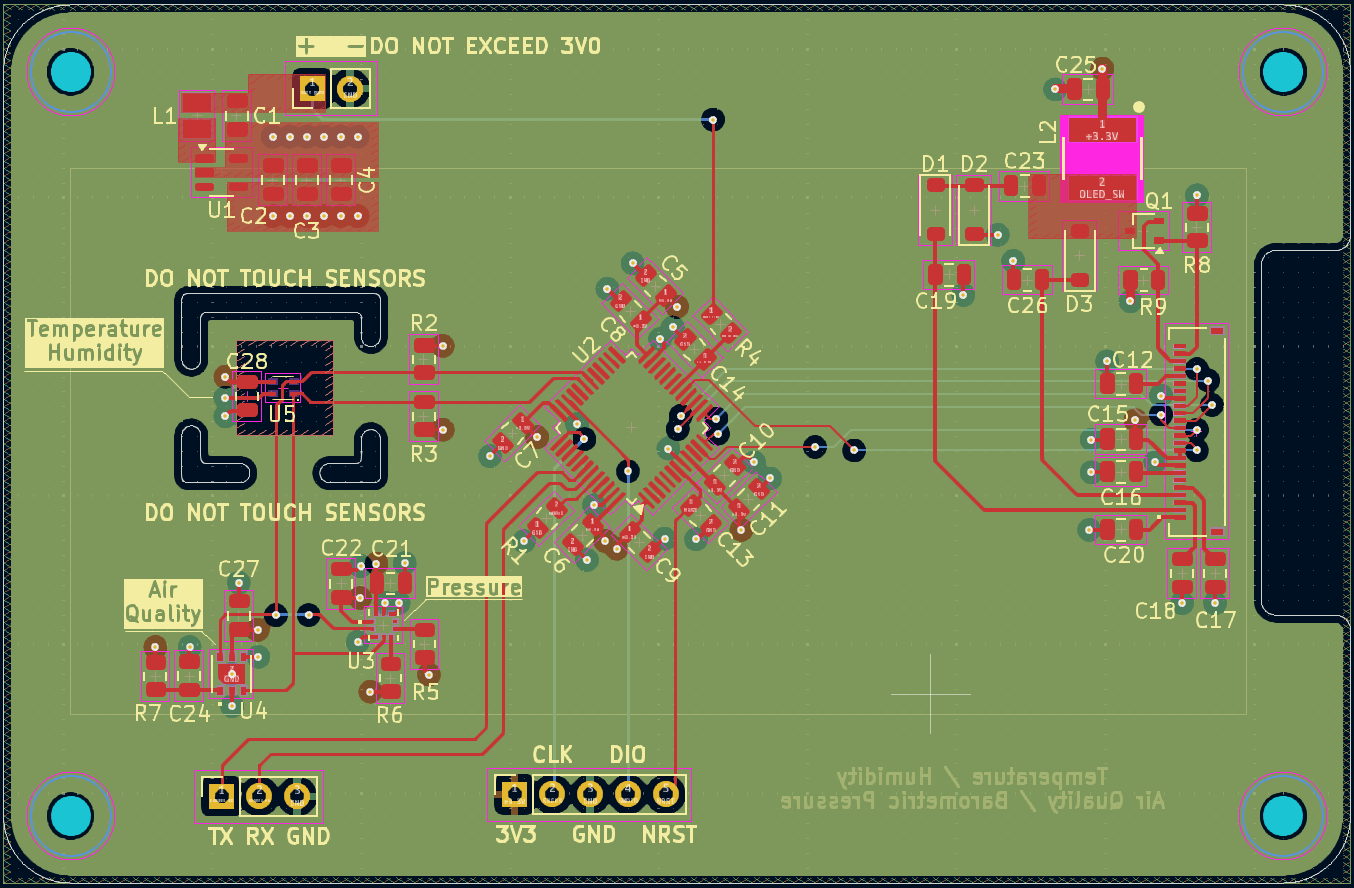
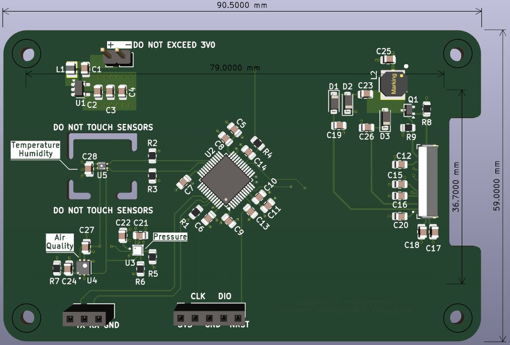
- Layout completed.
- Manufacturing files have been sent off as of this afternoon.
To do:
- Check the BOM and see what I have and what I need.
- Order what I need from Digikey.
- Hope and pray that I've not screwed up the schematic and layout...
Schematic:

Layout:
As the ePaper display will be mounted to the "back" of the PCB and I needed mounting holes, I had quite a lot of space to work with. In regard to the ePaper display, I still need to figure out the best way to mount it; double-sided tape perhaps?
I attempted to keep all of the high frequency switching stuff near the top of the board and away from SPI and I2C traces. Not entirely certain this is the best layout, but hopefully it'll be good enough for a first revision.
Additionally, for the SHT45, I introduced cutout areas around the sensor and removed all copper below the sensor. Hopefully, this will prevent inaccuracies (as best as I can do, at least) in temperature due to any heat generated by the SGP41's built in heater. Then again, as I anticipate only performing sensor readings every 15-30 minutes, this may be overkill as the board will generally be cool - or at near ambient temperature - when the uC wakes up and grabs sensor values.


Discussions
Become a Hackaday.io Member
Create an account to leave a comment. Already have an account? Log In.